In wall - PCB, (AC to DC 5v)
-
I started a new thread for my attempt at a custom box design.
http://forum.mysensors.org/topic/2509/box-for-in-wall-pcb -
I have also started my own thread to save me clogging your development thread up @sundberg84. I'm hoping that we can gather seperate ideas and then discuss to develop products that are a creation of many of opinions/improvements.
-
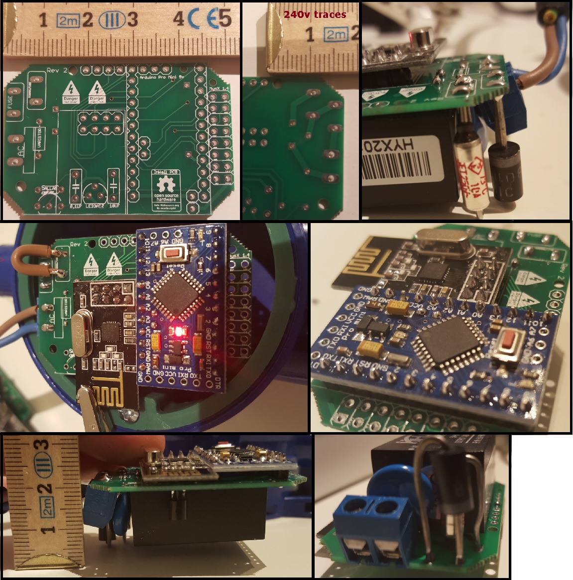
I recieved my PCB today - Yea!
The good news is - its working, and it fits inside my wall socket.
The bad news is that as always i will need another revision - the hole for the fuses are to close to each other.Some pictures:
Anyone with any input on this?
Controller: Proxmox VM - Home Assistant
MySensors GW: Arduino Uno - W5100 Ethernet, Gw Shield Nrf24l01+ 2,4Ghz
MySensors GW: Arduino Uno - Gw Shield RFM69, 433mhz
RFLink GW - Arduino Mega + RFLink Shield, 433mhz -
I recieved my PCB today - Yea!
The good news is - its working, and it fits inside my wall socket.
The bad news is that as always i will need another revision - the hole for the fuses are to close to each other.Some pictures:
Anyone with any input on this?
@sundberg84 Fantastic news on receiving this before the Christmas dull in mailing! Super happy for you to receive, populate and get working your custom board dude! I have no input other than to congratulate you on a successful board, shame on the fuse issue :( Could i ask you, do you have any components sitting under your nRF module?
I'm currently having a few little teething issues on getting the board down in size slightly, it should fit my application as it is right now, but i would like it a little smaller. The thing that is really holding me back on sizing is the screw terminal being a 4 pos block. I might have to reset to maybe 2 x two pos, or even some singles. Although i only need two switches on this particular application, i would like to make it accept 3 so just in case i install a 3 way switch somewhere, i am able to use this board, rather than creating another.
Hopefully I'm not too far away from completion now.
-
Nice! Good images, and thanks for the scale. Is your wall box also 4 cm deep, like the ones I have in my house?
-
Hi all,
It looks very good @sundberg84, It's still a little bit bigger than fibaro switch but costs much much less :) Looking forward to see your next revisionIs it any chance to place another screw terminal to allow turn on/off not only via radio but with the local button as well?
From other side as a workaround it still should be possible to hard soldering some wires to appropriate pin on arduino side.I'm wondering why some Asia manufacturer is not able to build a tiny pcb with integrated arduino, nrf radio, ac-dc trafo and relay on one single board to keep small footprint.
-
I recieved my PCB today - Yea!
The good news is - its working, and it fits inside my wall socket.
The bad news is that as always i will need another revision - the hole for the fuses are to close to each other.Some pictures:
Anyone with any input on this?
@sundberg84 Good job and nice fit! Looks like you can even make the discussed separate box-in-box for it if you like.
Do you have a BOM of the parts you used this far? And which ones you need to replace or move around. -
@samuel235 - No components between the NRF and the PCB but yes, if you mean on the other side of the pcb. There is the 5->3.3v converter and caps.
@martinhjelmare - Yes, 4.5cm it seems but there is some room on the sides so i hope to be able to squise in a relay.
@łukasz-rybak - You can connect a local button between d3 and gnd on the MYSX connector on the right side. This can read the switch and change a relay depending on what state the switch is in.
@m26872 - Yea, lets hope so... ill do another revision of the board and lets see where this ends up.
-
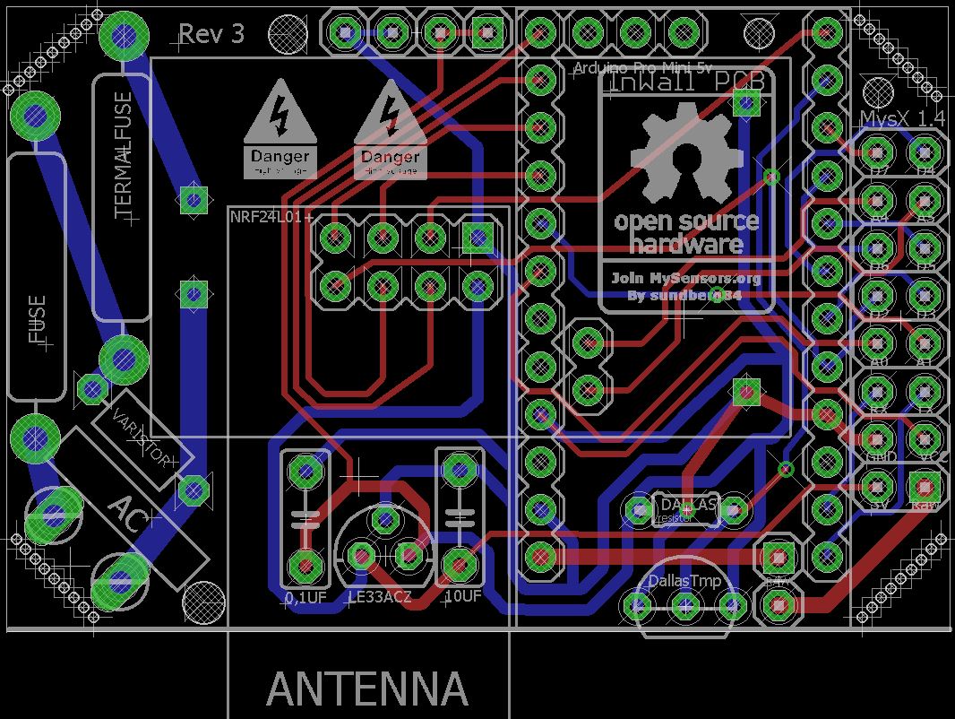
So, my rev 3 is coming along:
- moved the Dallas temp sensor
- added some more space for the 240v fuses:
- labels changed
The BOM? Is that the parts used?
I have used what we concluded here:
http://forum.mysensors.org/topic/1607/safe-in-wall-ac-to-dc-transformersThis is what i bought (no garantees given this works/doesnt burn)
HKL-PM01 http://www.ebay.com/sch/sis.html?_nkw=HLK-PM01+AC-DC+220V+to+5V+Step-Down+Power+Supply+Module+Household+Switch+Q15274&_id=351418782712&&_trksid=p2057872.m2749.l2658
(DO NOT BUY THIS!!)Fuse http://www.ebay.com/itm/111433875797?_trksid=p2057872.m2749.l2649&ssPageName=STRK%3AMEBIDX%3AIT
Thermal Fuse http://www.ebay.com/itm/221560426284?_trksid=p2057872.m2749.l2649&ssPageName=STRK%3AMEBIDX%3AIT
Varistor http://www.ebay.com/itm/260848704608?_trksid=p2057872.m2749.l2649&ssPageName=STRK%3AMEBIDX%3AITPro Mini 5v
Nrf radio
LE33a http://www.ebay.com/itm/400691492273?_trksid=p2057872.m2749.l2649&ssPageName=STRK%3AMEBIDX%3AIT -
@samuel235 - No components between the NRF and the PCB but yes, if you mean on the other side of the pcb. There is the 5->3.3v converter and caps.
@martinhjelmare - Yes, 4.5cm it seems but there is some room on the sides so i hope to be able to squise in a relay.
@łukasz-rybak - You can connect a local button between d3 and gnd on the MYSX connector on the right side. This can read the switch and change a relay depending on what state the switch is in.
@m26872 - Yea, lets hope so... ill do another revision of the board and lets see where this ends up.
@sundberg84 said:
@samuel235 - No components between the NRF and the PCB but yes, if you mean on the other side of the pcb. There is the 5->3.3v converter and caps.
Just to let you know, I meant in between the nRF board and the PCB, so thank you for letting me know :)
Rev 3 is looking pretty neat and tidy if i must say so. Keep up the awesome design work, I'm learning off of you, thank you! ;)
-
@sundberg84 Yes, the BOM is the list of all components that populates your PCB. References, values, source and all other specifications that the "manufacturer" will need.
I was actually mostly interested in the fuse looking like a big diode in your picture. Is it ordered from that link you showed? Which value is it?
-
@m26872 Its the slow blow fuse, and I ordered 240v, dont remember which current and that is offcourse whats interesting. On a business trip but can check this weekend when i get home. The datasheet for the HLK refers to:
Maximum input current ≤0.2 A
Input current surge ; ≤10 AController: Proxmox VM - Home Assistant
MySensors GW: Arduino Uno - W5100 Ethernet, Gw Shield Nrf24l01+ 2,4Ghz
MySensors GW: Arduino Uno - Gw Shield RFM69, 433mhz
RFLink GW - Arduino Mega + RFLink Shield, 433mhz -
@m26872 Its the slow blow fuse, and I ordered 240v, dont remember which current and that is offcourse whats interesting. On a business trip but can check this weekend when i get home. The datasheet for the HLK refers to:
Maximum input current ≤0.2 A
Input current surge ; ≤10 A@sundberg84 Could I ask where you order your boards from, which manufacturer do you use and would you recommend them?
-
I order from itead. Works great and good quality.
-
@m26872 Its the slow blow fuse, and I ordered 240v, dont remember which current and that is offcourse whats interesting. On a business trip but can check this weekend when i get home. The datasheet for the HLK refers to:
Maximum input current ≤0.2 A
Input current surge ; ≤10 A@sundberg84 The closest fuse-alike I've found in a DO-204 (semiconductor-) package, is the TVS diode. Typical breakdown voltage seems to usually be a lot lower than 230V, so I guess you should apply a low voltage (<10V) if you want to test if it conducts. Fuse break current is the most interesting test of course.
-
I order from itead. Works great and good quality.
@sundberg84 They look like they provide a pretty stable and awesome service. What sort of turn around did you get from ordering to receiving the PCB?
-
@mzuidwijk : The HLK library for eagles: HKLPM01.rar
@m26872 : Since the ciriut works it conducts, i have not tested at which point it breaks because i dont have that equipment :( would be great if we somehow could estabilsh the right compont to use.Controller: Proxmox VM - Home Assistant
MySensors GW: Arduino Uno - W5100 Ethernet, Gw Shield Nrf24l01+ 2,4Ghz
MySensors GW: Arduino Uno - Gw Shield RFM69, 433mhz
RFLink GW - Arduino Mega + RFLink Shield, 433mhz -
@mzuidwijk : The HLK library for eagles: HKLPM01.rar
@m26872 : Since the ciriut works it conducts, i have not tested at which point it breaks because i dont have that equipment :( would be great if we somehow could estabilsh the right compont to use.@sundberg84 Of course it conducts, probably bidirectional too since it works well for you. That's why I suggested a TVS diode. The test was meant as an easy way to find more info even if it does not fully rule out that it still could be something else than a normal fuse. I'm sure you have possibility to test if something conducts or not at low voltages. If it does not, it is not a fuse. Use a new component since it could be a "fail-short" type one.
Then if you connect it in series to a load (> 230V*0.2A "=" 46W), it should blow if it's a fuse.That first fuse is the no1 safety component and should be trusted. I would never just rely an some 10A house fuse to a diy design like this. Removing the varistor could limit the failure modes in the meantime.
-
@m26872 Ok, you seem to know more about this - i have pretty much tried to sum up what was told in the safe-in-wall thread.
Do you agree with that thread or would you do it some other way ? (High power parts and HKL PM01).Controller: Proxmox VM - Home Assistant
MySensors GW: Arduino Uno - W5100 Ethernet, Gw Shield Nrf24l01+ 2,4Ghz
MySensors GW: Arduino Uno - Gw Shield RFM69, 433mhz
RFLink GW - Arduino Mega + RFLink Shield, 433mhz