How do I use the interrupt
-
I couldn't stand it and wired up the motion sensor I have (HC-SR501) and tested with the MotionSensor example code (MySensors 1.4b).
Sensor supply is 5V, sensor output is connected to pin 2 or Arduino. Pin 2 is configured to be an input pin and generate an interrupt when any change on the pin state is detected. You don't need to attach a resistor as the sensor outputs either a low state or high state (3V3 according to my data). You *could *connect a small resistor (e.g. 100ohms) between sensor output and Arduino pin to limit the current.
I only changed the SLEEP_TIME to 30000 and DIGITAL_INPUT_SENSOR to 2. Downloaded the sketch to Uno and ran it.
Works as expected! Sensor sleeps and is woken by any change in interrupt pin (this is a contradiction with the ATmega datasheet which states it should only act on low level!).
So a value of 1 is sent when the sensor detects motion, 0 when motion 'goes away'.Hopefully this answers your question :-)
-
While you guys are at it, can you also confirm that the PIR module does indeed work as intended on 3.3V input like this guy claims:
http://techgurka.blogspot.se/2013/05/cheap-pyroelectric-infrared-pir-motion.html
There are a couple of different revisions of the HC-SR501 through so not all of them have actual pins for for H/L selection. Some just have small solder pads.Bypassing the regulator, and eventually removing it would solve a lot of problems for battery sensors. But as noted, it should probably output 3.3V when HIGH regardless so no need to worry.
@bjornhallberg thanks for the hint! The 5v supply kept me from battery powering it.
I seem to have the same sensor as in the article.
I'll setup some test and also measure the current the sensor consumes to get an estimation of battery life.
To be continued.... -
Here it is.
The HC-sr501 seems to work with 3.3v (have not tested it with 3v though).
With 5v the output pin generates about 500mv low and 3.5v high.
With 3.3v the output pint generates about 390mv low and a little under 3v high.Nice I think...
-
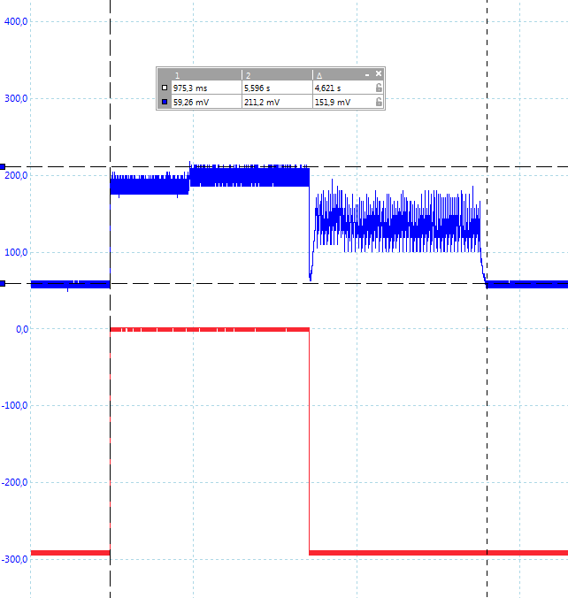
Tested HC-SR501 with 2xAA Alkaline (2.86V) still works OK.
Measured power usage with uCurrent & Scope (2.86V, 7133-1 voltage converter bypassed):
Blue = current in micro-Amps., Red = detection output
So sleeping current is roughly 60uA (171uW), peak current is 212uA.
Probably this will improve by disconnecting the 7133-1 voltage converter.
Update: Repeated measurement with 7133-1 completely removed from PCB -- Makes no difference, so there's no need to remove it.Given the example battery-life calculation from MySensors (http://www.mysensors.org/build/battery) you could run this sensor (alone!) from a battery for roughly 16months!
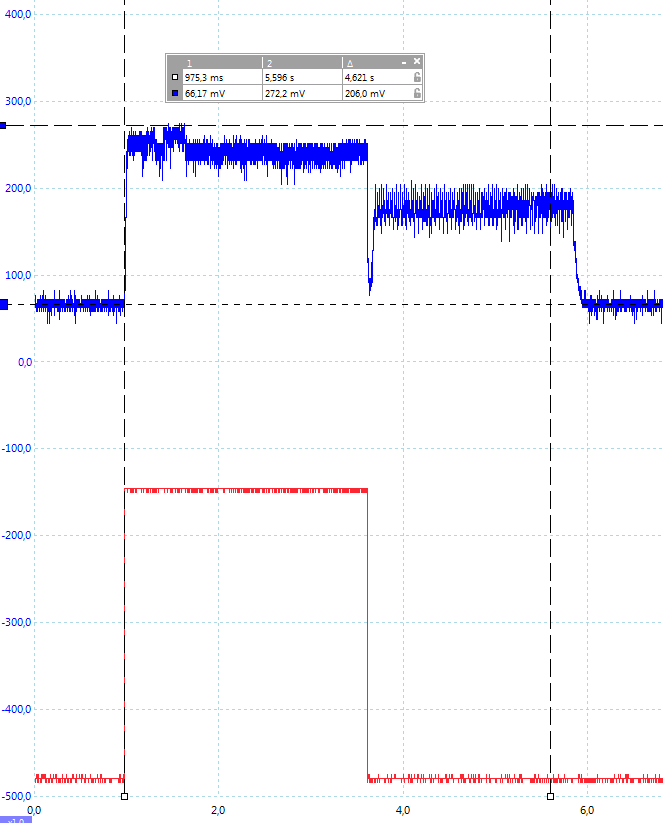
Same chart for 4.73V supply (7133-1 voltage converter used):
Blue = current in micro-Amps., Red = detection output
So sleeping current is roughly 66uA (312uW), peak current is 272uA.http://yveaux.blogspot.nl
-
Tested HC-SR501 with 2xAA Alkaline (2.86V) still works OK.
Measured power usage with uCurrent & Scope (2.86V, 7133-1 voltage converter bypassed):
Blue = current in micro-Amps., Red = detection output
So sleeping current is roughly 60uA (171uW), peak current is 212uA.
Probably this will improve by disconnecting the 7133-1 voltage converter.
Update: Repeated measurement with 7133-1 completely removed from PCB -- Makes no difference, so there's no need to remove it.Given the example battery-life calculation from MySensors (http://www.mysensors.org/build/battery) you could run this sensor (alone!) from a battery for roughly 16months!
Same chart for 4.73V supply (7133-1 voltage converter used):
Blue = current in micro-Amps., Red = detection output
So sleeping current is roughly 66uA (312uW), peak current is 272uA. -
@Yveaux Nice, have not yet tested the other sensor though.
Got it working, changed the sketch a little though.
I wanted 2 things:
- No reporting of status when there is no change
- 4 minutes real sleep before the next update when motion was detected
Work like a charm :)
Thank you guys!!!
void loop() {
  // Read digital motion value
  boolean motion = digitalRead( DIGITAL_INPUT_SENSOR ) == LOW;

  // Send debug output to serial monitor
  mprintln(PSTR("Motion sensor %s"), motion ? "ON" : "OFF" );

  if (lastMotion != motion) {
    lastMotion = motion;

    // Send motion value to sensor
    gw.send( msg.set( motion ? "1" : "0" ) );

    if (motion) {
      gw.sleep( SLEEP_TIME );
    }
  }

  gw.sleep( INTERRUPT, CHANGE, SLEEP_TIME );
}
Fulltime Servoy Developer
Parttime Moderator MySensors boardI use Domoticz as controller for Z-Wave and MySensors (previously Indigo and OpenHAB).
I have a FABtotum to print cases. -
Got it working, changed the sketch a little though.
I wanted 2 things:
- No reporting of status when there is no change
- 4 minutes real sleep before the next update when motion was detected
Work like a charm :)
Thank you guys!!!
void loop() { // Read digital motion value boolean motion = digitalRead( DIGITAL_INPUT_SENSOR ) == LOW; // Send debug output to serial monitor mprintln(PSTR("Motion sensor %s"), motion ? "ON" : "OFF" ); if (lastMotion != motion) { lastMotion = motion; // Send motion value to sensor gw.send( msg.set( motion ? "1" : "0" ) ); if (motion) { gw.sleep( SLEEP_TIME ); } } gw.sleep( INTERRUPT, CHANGE, SLEEP_TIME ); }@marceltrapman Great you managed to get it working!
Just wondering about one thing:boolean motion = digitalRead( DIGITAL_INPUT_SENSOR ) == LOW;This suggests motion is detected when input pin is LOW, while I clearly see it rise when motion is detected...
Where's the catch? -
@Yveaux said:
Where's the catch?
Because I was testing 2 different types of motion sensors I decided (for now) against the HC-SR501.
I was just being lazy and did not want to bother with checking/setting the timeout and sensibility on the sensor itself.
The other one behaves correct with this test and not when I set it to HIGH.
And behaviour is consistent... -
Tested HC-SR501 with 2xAA Alkaline (2.86V) still works OK.
Measured power usage with uCurrent & Scope (2.86V, 7133-1 voltage converter bypassed):
Blue = current in micro-Amps., Red = detection output
So sleeping current is roughly 60uA (171uW), peak current is 212uA.
Probably this will improve by disconnecting the 7133-1 voltage converter.
Update: Repeated measurement with 7133-1 completely removed from PCB -- Makes no difference, so there's no need to remove it.Given the example battery-life calculation from MySensors (http://www.mysensors.org/build/battery) you could run this sensor (alone!) from a battery for roughly 16months!
Same chart for 4.73V supply (7133-1 voltage converter used):
Blue = current in micro-Amps., Red = detection output
So sleeping current is roughly 66uA (312uW), peak current is 272uA. -
@Yveaux Update: Repeated measurement with 7133-1 completely removed from PCB @ 3v3 -- Makes no difference, so there's no need to remove it.
@Yveaux said:
@Yveaux Update: Repeated measurement with 7133-1 completely removed from PCB @ 3v3 -- Makes no difference, so there's no need to remove it.
Let me be sure I understand. You are comparing feeding battery power to the 3.3v circuit of the motion detector, with and without the 7133-1 connected, right? (When the 7133-1 is connected, you are feeding power to its output), right?
EDIT - It was a dumb question, followed the link to read that the regulator has a 1.7v dropout, so obviously you are not going thru it!
Some regulators don't like being fed power to their output and waste current, but apparently this one doesn't care, which is handy.
-
While you guys are at it, can you also confirm that the PIR module does indeed work as intended on 3.3V input like this guy claims:
http://techgurka.blogspot.se/2013/05/cheap-pyroelectric-infrared-pir-motion.html
There are a couple of different revisions of the HC-SR501 through so not all of them have actual pins for for H/L selection. Some just have small solder pads.Bypassing the regulator, and eventually removing it would solve a lot of problems for battery sensors. But as noted, it should probably output 3.3V when HIGH regardless so no need to worry.
While you guys are at it, can you also confirm that the PIR module does indeed work as intended on 3.3V input like this guy claims:
http://techgurka.blogspot.se/2013/05/cheap-pyroelectric-infrared-pir-motion.html
There are a couple of different revisions of the HC-SR501 through so not all of them have actual pins for for H/L selection. Some just have small solder pads.Hi all, does anyone know of an eBay listing that actually ships the HC-SR501 with the pins for H/L selection? I bought some of these: http://www.ebay.com/itm/310574919531, which shows the pins in the pictures and the description mentions being able to select H/L with a jumper, but the ones that arrived don't actually have the pins and have the solder pads instead.
Thanks
Al