In wall light switch node - Custom PCB
-
So, i have it working using the following board.txt config:
######## Settings for

ATmega328 8MHz Internal clock Brown-out detection 1.8v
atmega328bb.name=ATmega328 on a breadboard (8MHz internal clock) BoD1.8
atmega328bb.upload.tool=avrdude
atmega328bb.upload.protocol=stk500
atmega328bb.upload.maximum_size=30720
atmega328bb.upload.speed=57600
atmega328bb.bootloader.tool=avrdude
atmega328bb.bootloader.low_fuses=0xE2
atmega328bb.bootloader.high_fuses=0xDA
atmega328bb.bootloader.extended_fuses=0x06
atmega328bb.bootloader.path=arduino:atmega
atmega328bb.bootloader.file=atmega/ATmegaBOOT_168_atmega328_pro_8MHz.hex
atmega328bb.bootloader.unlock_bits=0x3F
atmega328bb.bootloader.lock_bits=0x3F
atmega328bb.build.mcu=atmega328p
atmega328bb.build.f_cpu=8000000L
atmega328bb.build.core=arduino:arduino
atmega328bb.build.variant=arduino:standard
However, no matter what I did I couldn't get it to upload via FTDI. I've tried looking at the Arduino Pro Mini settings in boards.txt to see what 'upload.tool' it uses, AVRDUDE, same as i specified. I also then went to the google docs for the boards.txt reference file, that advises everything i did too. I'm a little stumped. All that i can think of is that i have wired it incorrectly on the pcb. Whats your thoughts on this?
-
@m26872 said:
And in this case it´s stock Arduino, so why question it.
I'm not questioning it, I just wanted to learn how to do it for if i ever came across a need to modify a bootloader i would then know how to record its size for the fuse burning.
So the '0x06'-kind of notation didn't work either? Strange.
When i set the boards.txt file to read 0x06 it worked perfect, which insinuates that it couldn't burn the chosen BoD, even though the fuse calculator says to ignore the error of the extended fuse, it should burn it even though it gives the error. I'm interested in trying to burn the extended fuse in normal binary rather than hexa. But i doubt it would work anyway.
@samuel235 said:
I'm not questioning it,
I'm not saying you do, I just told how I think of it.
I'm interested in trying to burn the extended fuse in normal binary rather than hexa.
Why, when the result is exactly the same?
Also, I'm not familiar with from where the "binary or hexa" comes from? They're both hexadecimal notation as far as I can see. -
I'm not sure what is your problem with ftdi.maybe wirings...do you have cts to gnd, and of course dtr to dtr, only one vcc active...??? Maybe you should try to burn original arduino ide bootloader and then ftdi upload attempts. If it still doesn't work, it could be the wirings...
for hexa vs binary..in some case binary notation can be useful, but for fuses, I prefer hexa: shorter, no possibility of mistakes by missing/miscounting one "1" or "0" bit ;) -
@m26872 - I wanted to try it because i'm sure i read somewhere that the ATmega328 can't accept Hexa as fuses. But i doubt that information is valid if i'm honest with you.
@scalz - I have dtr to dtr and cts linked to ground. I also only have one VCC pin (which obviously goes to VCC). I'll be perfectly honest with you; the boart.txt setting i posted above, i thought that was using the arduino .hex bootloader, please inform me if i'm in correct in that.
-
This is the board layout, if you guys can see any issues with my FTDI connections/pinout please advice me that you do, I will get that sorted for revison 3 of the board. If i'm honest, I don't mind burning the sketches with the ISP programmer everytime, so I'm very tempted to remove the FTDI, allowing a smaller board still.
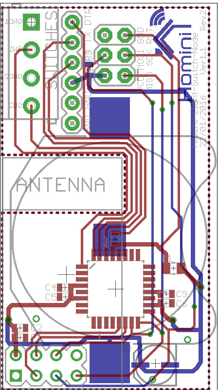
MySensors 2.1.1
Controller - OpenHAB (Virtual Machine)
Gateway - Arduino Mega MQTT Gateway W5100 -
This is the board layout, if you guys can see any issues with my FTDI connections/pinout please advice me that you do, I will get that sorted for revison 3 of the board. If i'm honest, I don't mind burning the sketches with the ISP programmer everytime, so I'm very tempted to remove the FTDI, allowing a smaller board still.
@samuel235 How do you debug through ISP ?
Have you tested your FTDI USB-serial converter with ArduinoProMini or something? -
@samuel235 How do you debug through ISP ?
Have you tested your FTDI USB-serial converter with ArduinoProMini or something?@m26872 - I haven't tried it out with a arduino pro mini, because i don't have one. However, tomorrow, I will get a Arduino nano out and sort some testing of my FTDI converter on that. I'm hoping that works and its just a simple wiring issue on my board.
From your statement of "How do you debug through ISP?" I'm guessing that it isn't possible too, or was that a genuine question? If its not possible then I will keep the FTDI connectors on the board.
MySensors 2.1.1
Controller - OpenHAB (Virtual Machine)
Gateway - Arduino Mega MQTT Gateway W5100 -
@m26872 - I haven't tried it out with a arduino pro mini, because i don't have one. However, tomorrow, I will get a Arduino nano out and sort some testing of my FTDI converter on that. I'm hoping that works and its just a simple wiring issue on my board.
From your statement of "How do you debug through ISP?" I'm guessing that it isn't possible too, or was that a genuine question? If its not possible then I will keep the FTDI connectors on the board.
@samuel235
I think you should get yourself a APM (ArduinoProMini) as a reference device. While waiting I think you could wire a DTR circuit to your Uno or Nano and see if you can get your FTDI to talk through rx/tx there.The "debug through ISP" is a genuine question. My guess is that it's possible if your bootloader, programmer and IDE support it.
-
Yea, we talked about this as well @m26872 the other night... and to make it easy I also suggest having the fdti connector - if your node is about other to use it (new members to mysensors) thats they easiest way to be able to debug.
Its possible to debug through SPI, [1, 2 , 3] but requiers extra code in your sketch. With fdti you can just user serial.println();Also it looks like you need an second arduino acting with some code... to read and print on that second device serial.... have not read everything through... but its a bit of work it seems.
-
@m26872 - I'm going to get a APM sorted asap. Then i'll get to try my FTDI converter checked.
@sundberg84 - Way too much hassle for what its worth, I will trouble shoot and sort out my existing connection for FTDI.
-
Current Situation Update
The board is completely populated with correct hardware, tested for 24 hours functioning, working completely fine. There is a slight delay now and then between the switching state and the light illuminating, only sometimes, but nothing major (1/1.5 seconds). The fuse setting and the bootloader burning went unbelievably smooth, very easy once i got my head around all the different settings needed and why they were needed in certain situations. I'm currently using the default arduino bootloader (ATmegaBOOT_168_atmega328_pro_8MHz.hex), burnt with a ISP connection using AVRdudess for the software. I'm unsure if the device is sleeping between readings of the switch but that will be easily noticed soon as i get my FTDI situation fixed.
Talking about FTDI Issues, I'm currently stuck with not being able to upload a sketch through FTDI, its hanging on the "upload" status in Arduino's IDE. I don't think it is a driver issue as my computer has always been configured to never update a driver through windows update (Just confirmed this through the advanced computer settings). The driver that I'm currently using is version 3.3.2011.11. However, if there is no issue with my wiring (shown in a recent previous post/comment above here) i'm struggling to see what else the issue could be other than soldering issues, which i can't notice from a few look over attempts using a 25x magnifier, I will give it another look over to make sure though.
Which attempting to troubleshoot this, I have noticed that if I have the MYSbootloader on the chip and then attempt to upload a sketch (which i know wont work anyway due to MYSbootloader settings/usage rules) I get the generic message of memory allocation:
Sketch uses 13,678 bytes (44%) of program storage space. Maximum is 30,720 bytes.
Global variables use 438 bytes (21%) of dynamic memory, leaving 1,610 bytes for local variables. Maximum is 2,048 bytes.
Where as if I use the default arduino bootloader I only get:
Sketch uses 13,678 bytes (44%) of program storage space. Maximum is 30,720 bytes.
Global variables use 438 bytes of dynamic memory.
It completely misses out showing what space is left for the local variables. Could this shine any light onto the issue? The actual error that I am getting for the MYSbootloader version (after waiting literally over 1 minute from pressing upload), again that is expected, however the default bootloader version just hangs in the uploading state, its been there for well over 5 minutes without giving me an error now. Just to add, they both have the same 'upload.speed=57600' in their respected boards.txt config.
The FTDI Issue is my only major issue on this board now, revision 3 will be just minor fixes, such as adding pull-up resistors between the switch and VCC, a more detailed list will be announced when revision 3's designing process starts.
-
Just to let everyone that is reading this thread know that it is possible to brick your uC with the simplest of mistakes. It would seem that i have bricked my uC by burning the Arduino Pro Mini bootloader to it. The file that i burnt was 'ATmegaBOOT_168_atmega328_pro_8MHz.hex' designed for the Arduino Pro or Pro Mini (3.3v, 8MHz). I will be perfectly honest and admit that i genuinely don't know why it bricked it. I just thought that as long as the uC signature matched that of the bootloader you was burning it can be any .hex file, as long as it matched that uC. Seems that for some reason this didn't like it. If someone would like to give some more in-depth information regarding this to just allow people here a little more knowledge on this subject to aid in them not making the same mistake, that would be appreciated by all.
-
I think this is why it doesn't work: The standard Pro Mini bootloader assumes a 8MHz external oscillator. This board hasn't got one, so the mcu gets no ticks.
I'm not sure but I think it is possible to re-orogram it.
@mfalkvidd - Oh C**P! An external OC, I completely forgot about it being a external one. Damn it! I'll get a 8MHz OC ordered and then just temp wire it into the circuit and hope it works by a huge bodge job. Do you have any thoughts on why I could upload via FTDI (as per the post above detailing everything regarding this issue)?
@sundberg84 - From our private messages, this is one of those very simple mistakes, made here by myself. Now, see how easy this mistake is? Don't be a fool like me and do the same haha!
-
@mfalkvidd - Oh C**P! An external OC, I completely forgot about it being a external one. Damn it! I'll get a 8MHz OC ordered and then just temp wire it into the circuit and hope it works by a huge bodge job. Do you have any thoughts on why I could upload via FTDI (as per the post above detailing everything regarding this issue)?
@sundberg84 - From our private messages, this is one of those very simple mistakes, made here by myself. Now, see how easy this mistake is? Don't be a fool like me and do the same haha!
@samuel235 I only see two possible causes. Either you changed the fuses unintentionally or you hw-bricked it with supply voltage, ESD or somehing. In the first case you'll just have to connect the external xtal ( likely 8MHz if you burned the standard APM 8MHz fuses).
-
Sorry, I have never tried rolling my own. But there's lots of clever people here, someone should have some advice.
@mfalkvidd - Alrighty :)
Just to let people know, i think that where i went wrong here is the fuses. Even though i burnt my fuses before the bootloader to the correct fuses that i want, I think that i didn't restart Arduino IDE after i saved the boards.txt file. Just make sure you don't do this! Always restart the IDE after altering any info in boards.txt.
-
@samuel235 I only see two possible causes. Either you changed the fuses unintentionally or you hw-bricked it with supply voltage, ESD or somehing. In the first case you'll just have to connect the external xtal ( likely 8MHz if you burned the standard APM 8MHz fuses).
@m26872 - Well to be honest, the way that i was throwing around possible solutions i'm guessing that its just a silly mistake with fuses in the boards.txt file. But would this just not burn the bootloader, i wouldn't have incorrectly burnt the fuses, i took 100% care over that, i came back here to double/triple check the fuses that i wanted from a previous comment i made. I burnt those and i changed the boards.txt and didn't restart the arduino IDE i dont think. But wouldn't this just not burn the bootloader?
Maybe if that is correct of me thinking this, then i could have bricked it with power/esd like you mentioned. Either way i have ordered some crystals to troubleshoot this.
-
The Arduino Pro Minis and another FTDI adapter has arrived today along with my crystals. We have news...
- Firstly, I got the fuses and bootloaders back to the correct ones (E2 DA 06) and the arduino bootloader, no issues here.
I then tried the new FTDI adapter - Still nothing. - Then it was the turn of trying an arduino pro mini with FTDI. Nothing there either. So i started to get puzzled at this point...
- I turn my mac on, tried it on there. I installed the drivers and allowed them to be used by running 'csrutil enable --without kext' in a terminal inside of recovery mode. Logged in, it recognized the FTDI chip, but couldn't upload to the APM. It is throwing out the same error of
"avrdude: stk500_getsync() attempt 10 of 10: not in sync: resp=0xee"
I'm yet to start googling the error code, that will be my next step to take. Its very much looking like the adapter is not able to chat to the board and since its happening on both boards i'm thinking that i may be doing something silly.
- Firstly, I got the fuses and bootloaders back to the correct ones (E2 DA 06) and the arduino bootloader, no issues here.
-
The arduino nano that i have uses the same serial chip that the FTDI adapter does, CH340G. Please correct me if i'm wrong in saying this, if i had a broken/incorrect driver for that CH340G then i wouldn't be able to upload via USB to my arduino nano?