In wall light switch node - Custom PCB
-
I have just received confirmation that the board house has released the PCB's. Lets see how long these take to get here! Itching to get this module on the move again. I will be back soon as they get here, don't go anywhere!
-
UPDATE!
I have just received all components for the boards, we're just waiting on the boards themselves to arrive from ITead Studios.
Time to get this project moving!
-
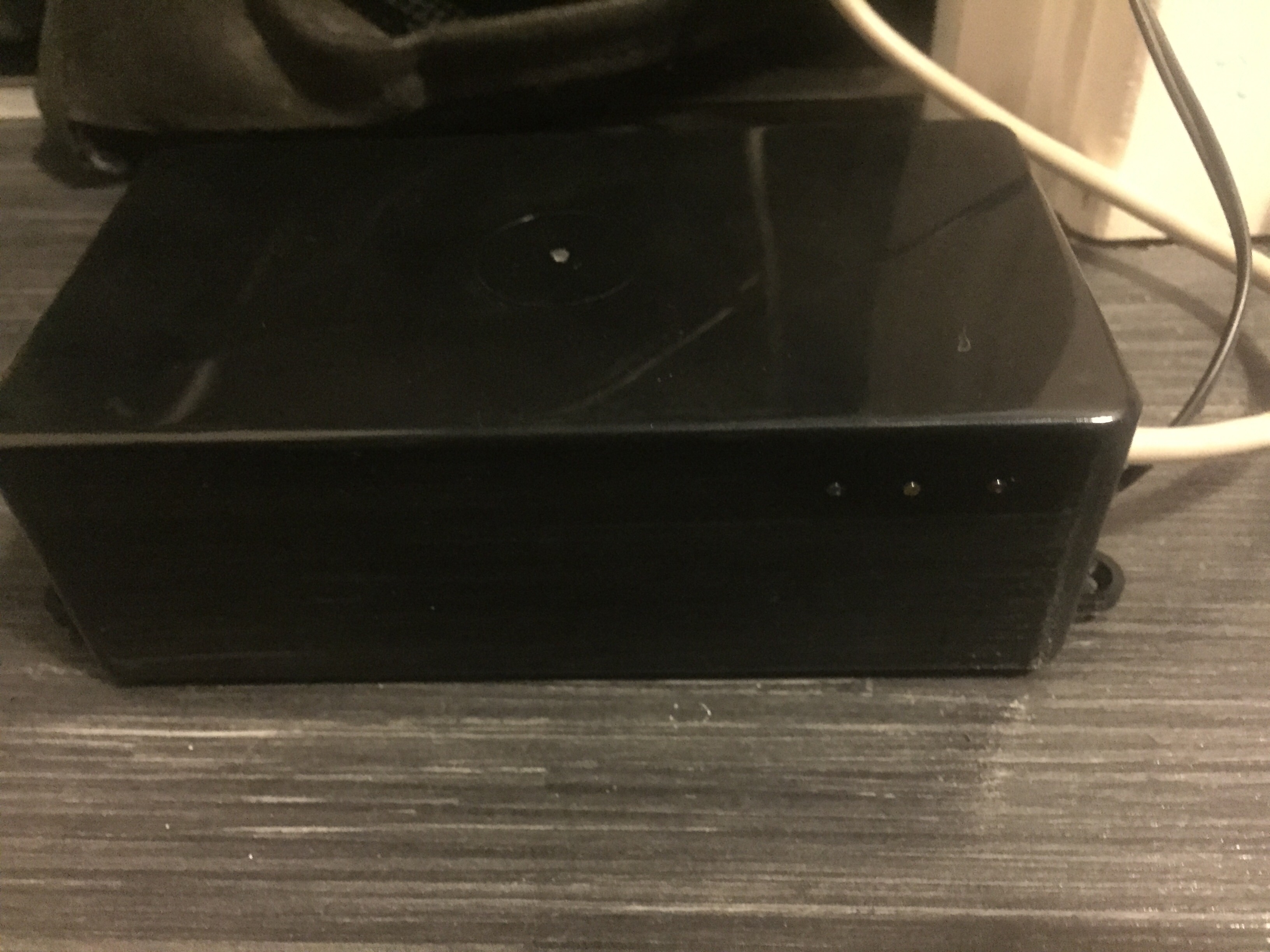
While waiting for my boards to arrive i decided to create a housing for my gateway including flashing status LEDs. Its in no means a finished product, but i feel its enough to house the gateway components while i'm building my network to save any incidents destroying the parts. Within the next few days i will get a guide up with images and maybe a video of the LEDs and their function up on a hardware guide topic.
-
So then, we have another update!
UPDATE!
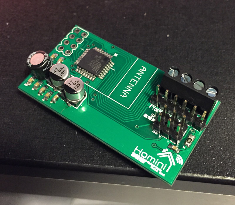
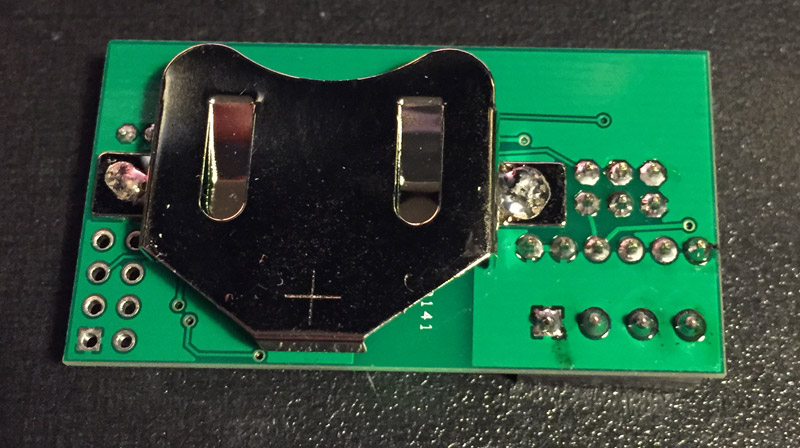
The boards ave arrived safe and sound, i have populated one of them with everything apart from the nRF module. So, its time to get the bootloader burnt. This is the daunting task for me, i have no idea what i am doing here, so if you guys feel like you could give me some helpful pointers in the right direction I would really appreciate all the help you can offer.
-
Hi! Depending on which bootloader you want, but why not go with the MySensors with OTA updates by tekka?
http://forum.mysensors.org/topic/838/windows-gui-controller-for-mysensors/75If you want the original arduino bootloader: https://www.arduino.cc/en/Hacking/Bootloader?from=Tutorial.Bootloader
-
Hi! Depending on which bootloader you want, but why not go with the MySensors with OTA updates by tekka?
http://forum.mysensors.org/topic/838/windows-gui-controller-for-mysensors/75If you want the original arduino bootloader: https://www.arduino.cc/en/Hacking/Bootloader?from=Tutorial.Bootloader
@sundberg84 - I was reading that exact post from tekka as you posted this. However, i'm probing around on my board and found for some reason my 3v line is 0.24v. So I have to do some investigation work on that this morning. Hoping the bootloader will be a piece of cake once the hardware is working as should be.
-
Hi! Depending on which bootloader you want, but why not go with the MySensors with OTA updates by tekka?
http://forum.mysensors.org/topic/838/windows-gui-controller-for-mysensors/75If you want the original arduino bootloader: https://www.arduino.cc/en/Hacking/Bootloader?from=Tutorial.Bootloader
@sundberg84 So i have my hardware issue corrected now. Am i reading Tekka's instructions correctly, this new board is to be connected through serial to my gateway and then programmed essentially by the gateway through MYSController which is connected to my gateway via ethernet? Does that sound correct?
-
No, i would recommend you have a look at some youtube tutorials. Im not familiar with programming through the ISP headers which i think you should do. I use a seperate arudino uno as ISP programmer.
-
@samuel235: cool. happy for you.
first you need to burn the bootlader in your atmel 328p. When it comes as ic-only, factory setting is 1mhz internal rc. and there is no bootloader yet. So you can't use ftdi at this moment, nor ota. So you need to burn the bootloader with avrspi. Like @sundberg84 said you can use the "arduino uno as isp programmer" method if you have an uno..On my side, I don't use this method, I prefer to use an usbasp. But both method works well.
When burning bootloader, you will need to set fuses too, corrsponding to the bootloader.Sorry, I have not much time to make an howto, just point you in some direction..i hope it helps a little bit.
Edit: you can find some howto here http://www.gammon.com.au/breadboard
@scalz I'm using a USBasp programmer, however i think i may have an issue with my reset pin. I have continuity on every other ISP header pin and the associated pin on the ATMega but not the reset pin. Is this normal, should i be seeing continuity between ISP RESET and pin 29 on the ATMega?
-
I think you should have continuity between avrspi connector RST pin and your atmega RST pin...don't see why not. Have you checked your routing? I think so...Maybe a bad solder on this pin???
-
I think you should have continuity between avrspi connector RST pin and your atmega RST pin...don't see why not. Have you checked your routing? I think so...Maybe a bad solder on this pin???
@scalz I may have found the problem, i have just completed a x25 magnification inspection on the boards and every board has atleast one filled VIA. I'm going to get a makeshift jumper in place on this board and test for continuity again.
I get continuity from the pin to the one side of the capacitor but nothing from the MEGA to the pin, it feels like the capacitor is stopping it coming through...
-
oki, so if continuity between rst atmega and one side of capacitor (dtr ftdi capacitor, right?) it should be ok. The capa is for dtr of ftdi (it is a trick for resetting atmega from ide when you want to upload).
Is your schematic updated on your first post? I don't see a 10k resistor pullup for rst...you need it to keep rst line to 1 and then when you push a rst button, or want to reprogram it by ftdi or avrspi, it will go to low/0 briefly to tell the mcu to reset.
if not done, try to connect a 10k res between your rst pin and vcc -
oki seems good. so I imagine you have continuity between rst atmega/one side of the 10k res. so what is your problem to program it?
when programming with avrspi, be careful with the fuses, especially for clock freq. For instance, if you set the clock fuse for external crystal and you have no onboard, then you could have some problem to re-set the fuse to internal clock as at this moment, the mcu will wait for an external clock. I am not sure as I have never tested this, and I am careful when I set the fuses, but in eventuality I am tired and make a mistake, I like to put a crystal footprint. but sometimes, you have not enough room unfortunately. -
oki seems good. so I imagine you have continuity between rst atmega/one side of the 10k res. so what is your problem to program it?
when programming with avrspi, be careful with the fuses, especially for clock freq. For instance, if you set the clock fuse for external crystal and you have no onboard, then you could have some problem to re-set the fuse to internal clock as at this moment, the mcu will wait for an external clock. I am not sure as I have never tested this, and I am careful when I set the fuses, but in eventuality I am tired and make a mistake, I like to put a crystal footprint. but sometimes, you have not enough room unfortunately.@scalz I get continuity from the ATMega to the resistor and one side of the cap. But its not flowing through the cap. So you think i should be good to program from there? I try to test a connection to the board with AVRDude, by running "C:>avrdude -c usbasp -p m328p" and then i get
avrdude: error: programm enable: target doesn't answer. 1 avrdude: initialization failed, rc=1 Double check connections and try again, or use -P to override this check. avrdude done. Thank you. -
yep, for capa it is not a problem. so it should work, but your log seems indicating a connection problem...but I don't see it :flushed: and I don't have much time for the moment...sorry.
for avrdude cli, I can't help you as I use avrdudess. no need of cli, a little bit easier. -
yep, for capa it is not a problem. so it should work, but your log seems indicating a connection problem...but I don't see it :flushed: and I don't have much time for the moment...sorry.
for avrdude cli, I can't help you as I use avrdudess. no need of cli, a little bit easier.@scalz While feeding the board 3v, every part of the VCC line from the battery to the chip is perfect, however if i test a VCC pin and a GND pin on the chip, it reads 0.06. Would this be an issue?
Maybe i should have connected all of the vcc's together or even pulled another to the battery directly, the only vcc connection going to the mega is from the DTR/RESET pin on the SPI header, that flows through the resistor to the mega. Is this an incorrect wiring issue?
-
Okay, so for some reason i seem to have not connected all the VCC's together unfortunately, i personally believe this is where my issue lies. If anyone feels differently, please shout out and let me know.
-
@samuel235: i have just looked briefly to your .brd this time ;) .So, for your next rev:
- you have airwire. You have to have no airwire at all or you must know what you do. Here you have an airwire on your batt which is not connected to mcu. So of course it can't work. You can fix this by soldering a wire between Batt_vcc and radio_vcc. it should work. Sometimes, when board is complex, you can't see everything, and sometimes airwire are micro..in eagle you can see these : File menu/run ulp/ and launch zoom_unrooted.ulp. It will highlight these.
- decoupling capa, which are not always mandatory, but for a mcu I would say yes, needs to be placed near the concerned chip. Your board is small so it should work. but it's something to know.
- for vcc, power line/rails, you are using 12mil (trace width I usually use mils unit as I am not familiar to inch! I'm french lol). I think it is rather small...For signals, it's ok. But for power, hum..I prefer not to go under 16mil and it's my limit. I like 20/24 or 32mils, all depends of the current.
As you can see, pcb design is a whole science! I would advise you to persevere, you will find very good starter howto for pcb designing at sparkfun. they rocks! adafruit too. It's like kung-fu, I like to say : the path/road is long ;) but finally it's very rewarding, yeah :smile: