5v on input to act like a button
-
I have a cheap 433mhz dorbell where I have removed the internal speaker and connected those cables to PIN 3 and GND.
When the remote button is pressed the cables supply 4.7v for a couple of seconds. I am powering the arduino from the same three AA batteries that runs the reciever and they are connected to the RAW, GBD on the arduino.
I have tried running http://www.mysensors.org/build/binary but that dont work. How would I modify that sketch to report button pressed when PIN 3 recieves ~5v.
Also the arduino is powerd up when I connect the speaker cables to PIN 3, GND and when GND from power supply. Even if I don´t connect the "power" frm the power supply.
-
The speaker is probably being sent an AC waveform, and the meter is just averaging it out so you see 4.7v. Likewise there may be some DC power from one side of it to gnd all the time since it's able to energize the Arduino.
Best would be to trace the circuit further back and see if there is something else you can tap into ahead of the speaker and it's driver.
If not you might be able to tie the speaker outputs together through a diode and a small resistor ( say 16Ohm ) and hook that to pin 3 -- or not depending on how it's driven. Or you could build a voltage dividing circuit to keep the AC voltage down to ~2v and use an ADC pin to read the waveform being sent to the speaker.
-
Solved it by using a optocoupler on the signal from the speakers.
-
But now I have a new problem. I am using this sketch:
// Enable debug prints to serial monitor
#define MY_DEBUG

// Enable and select radio type attached
#define MY_RADIO_NRF24
//#define MY_RADIO_RFM69

#include <SPI.h>
#include <MySensor.h>
#include <Bounce2.h>

#define CHILD_ID 3
#define BUTTON_PIN  3  // Arduino Digital I/O pin for button/reed switch

Bounce debouncer = Bounce();
int oldValue=-1;

// Change to V_LIGHT if you use S_LIGHT in presentation below
MyMessage msg(CHILD_ID,V_TRIPPED);

void setup()
{
  // Setup the button
  pinMode(BUTTON_PIN,INPUT);
  // Activate internal pull-up
  digitalWrite(BUTTON_PIN,HIGH);

  // After setting up the button, setup debouncer
  debouncer.attach(BUTTON_PIN);
  debouncer.interval(5);

}

void presentation() {
  // Register binary input sensor to gw (they will be created as child devices)
  // You can use S_DOOR, S_MOTION or S_LIGHT here depending on your usage.
  // If S_LIGHT is used, remember to update variable type you send in. See "msg" above.
  present(CHILD_ID, S_DOOR);
}


//  Check if digital input has changed and send in new value
void loop()
{
  debouncer.update();
  // Get the update value
  int value = debouncer.read();

  if (value != oldValue) {
     // Send in the new value
     send(msg.set(value==HIGH ? 1 : 0));
     oldValue = value;
  }
}
But I always get two triggers for one one button press. So the status is never changed like: Start state= ON, trigger OFF,TriggerON.
How can I make it so that It has to be more then 2 seconds apart from the triggers? So that the second rapid trigger command is filtered and not reported to domoticz ?
Also I would like the arduino to sleep as long as it is not detecting any button-press on PIN 3
-
Find out where the second pulse comes from and mitigate it.
You already have a debounce in there so increase the time there to start with.
You may also want to put a voltage divider in there too in case its actually a voltage spike as suggested already.
Is there any sort of relay involved in the whole circuit as it could also be chatter ?
-
OK, so if I change
debouncer.interval(5);to
debouncer.interval(1000);It will skip any button that are sent within 1 sec of the first buttonpress?
Regarding the voltage-spike I am using a optocoupler this time so there are no current sent to the arduino. It only acts like I connect PIN 3 to GND. -
Yup just change the debounce until your second trigger is no longer an issue. and well done going opto it's much safer.
That delay is only 5ms and the 1000 is 1s.
Times on delays are only approximate as the program takes time to run itself causing other slight delays. -
Ok, thanks. I think I read somewhere that there could be problems using debounce and sleep. Can I still use debounce and sleep until interrupt on Pin 3?
-
Ok, thanks. I think I read somewhere that there could be problems using debounce and sleep. Can I still use debounce and sleep until interrupt on Pin 3?
@Cliff-Karlsson I find it hard to figure out why you are getting a double trigger from your circuit. As you don't have a mechanical switch I think the cause is in the circuit. Can draw it or post a picture?
-
Well I "tapped" the signal from the speaker wires and as soward stated above "The speaker is probably being sent an AC waveform" -maybe that is causing the strange behaviour. I tried finding other places to use but most of them only gave me ~0.1V when the button was pushed and I thought I needed more power to trigger the octocoupler.
But can I modify the code somehow so that I culd use sleep on interrupt but force the arduino to only report the first "trigger" and the go back to sleep again?
I will upload a picture too if unclear.
@Cliff-Karlsson if you have an AC waveform it will probably be a lot of noise and/or a "sine like" wave of a certain frequency.
. Connected to an optocoupler this will trigger very frequently.
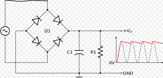
What I suggest you do is rectify the signal so that you get a "DC" signal to use as a trigger.
thnx wikiConnect the +Vo and GND to your optocoupler (in series with a resistor of around 470 Ohm). C1 = 100uF & R1 = 1kOhm will do to get a reasonable clean signal.
You can attach the optocoupler to the interrupt (D2 or D3) and do whatever you want with it using gw.sleep(...)
Hello! It looks like you're interested in this conversation, but you don't have an account yet.
Getting fed up of having to scroll through the same posts each visit? When you register for an account, you'll always come back to exactly where you were before, and choose to be notified of new replies (either via email, or push notification). You'll also be able to save bookmarks and upvote posts to show your appreciation to other community members.
With your input, this post could be even better 💗
Register Login