Rechargeable Lithium Ion Sensor Custom PCB
-
Hi!
Since a bunch of people already made a custom MySensors PCB, I decided to get used to Eagle and create my own board to fit my needs :smiley:
The key difference compared to other custom PCBs is the Lithium Ion Charging Circuit with micro USB connector. So you can just grab a flat smartphone battery with 1000 mAh or more and stick it under the PCB! This way you never have to worry about changing batteries, and even if your configuration consumes a lot of power, you can quickly recharge your sensor through the micro USB connector of the Li-Ion Charging Module.The board is currently only designed to work with the Arduino Pro Mini 3.3V version.
Version 0.1 is tested, I received the PCBs on 01/26/2016. Everything works fine (good radio range), there is only one little problem with the connection of the battery (but it is fixable; see post 52 in this thread for a fix)
So here are the specifications and features of my board:
- designed for cheap 3.3V Arduino Pro mini clones from china, for example this one
- 5x5cm
- uses jumper bridge to simply connect and disconnect the battery
- easy attaching of motion sensor (use 3.3V mod), DHT22 for Temp and Humidity Measurement and one switch (for example button- or reedswitch)
- small prototyping area on the backside
- uses TP4056 Li-Ion single cell Micro USB 1A charging circuit with battery protection (disconnects the power automatically if voltage drops below 2.4V
------> make sure you get the NEW version of the TP4056 with battery protection circuit!
remember to charge your li-ion 1-cell rechargeable battery with maximum 1C, so if you want to use a battery below 1000 mAh you need to make modifications to the module or the charging current will be way to high, which could result in an explosion (worst case) - I suggest to use the board with a smartphone battery, as they usually are very small and flat and have a high capacity for small money. I will use the galaxy s4 battery because it fits nearly perfect under the board and has 2600 mAh.
- Now with additional relay, properly connected using 2N2222A transistor, flyback diode, 1kΩ resistor and terminal block for easy attaching of "switchable things" to the relay
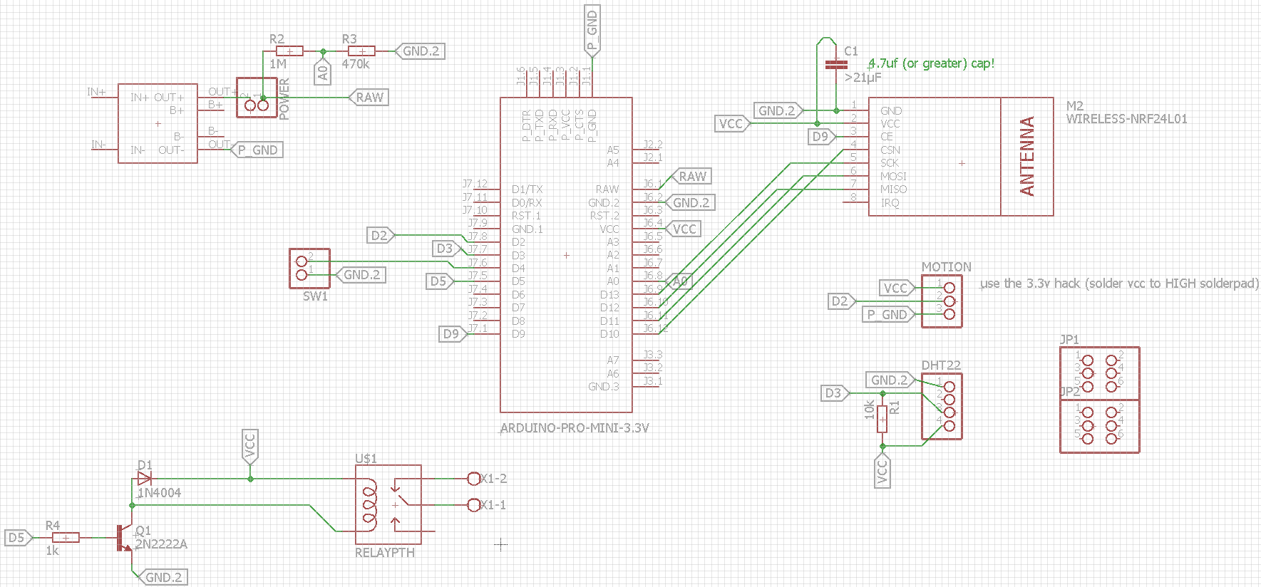
Schematics (Rev 1.0)
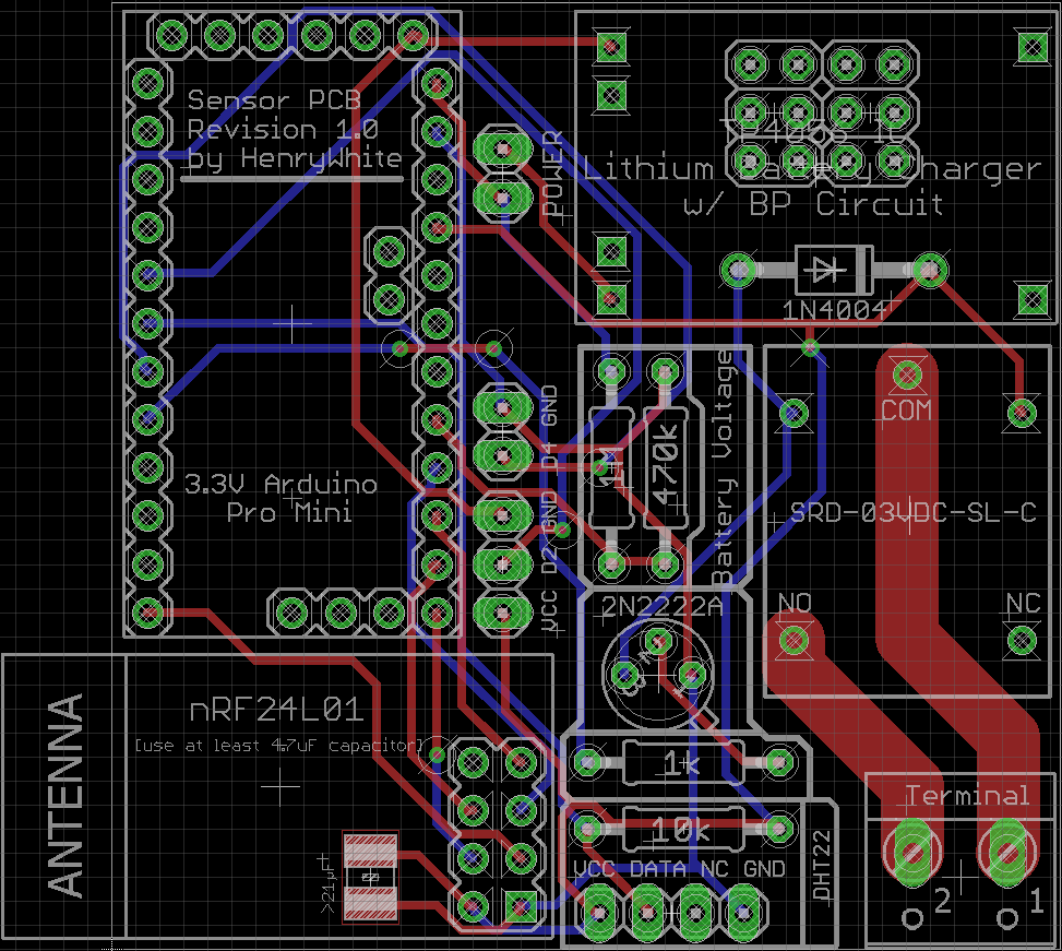
Board view (Rev 1.0)
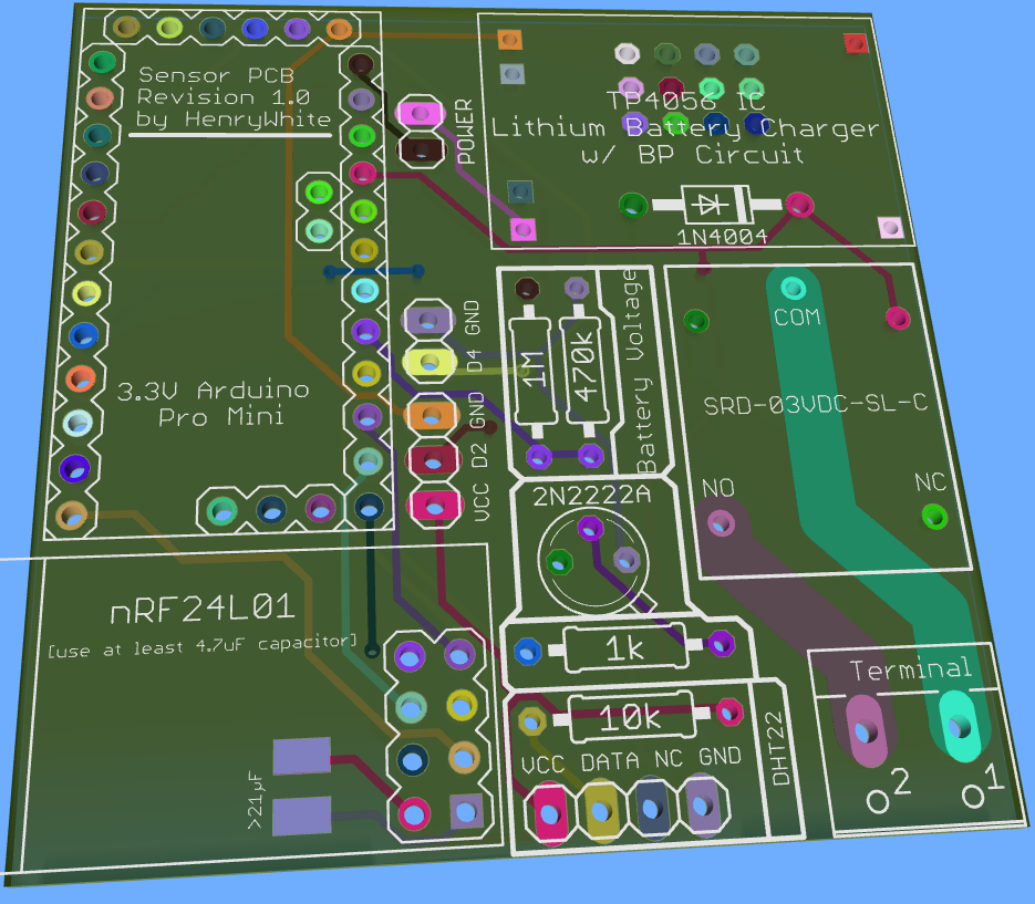
3D board view (Rev 1.0)
Build files
Rev 1.0:
- Now with additional relay, properly connected using 2N2222A transistor, flyback diode, 1kΩ resistor and terminal block for easy attaching of "switchable things" to the relay
- proper alignment of DHT22
Eagle files: 0_1453762986505_Sensorboard_v1.0.zip
Gerber files: 0_1453763061782_Sensorboard_v1.0_Gerber.zipRev 0.3: swapped footprints of DHT22 and prototyping area to prevent false temp measurements when charging the battery; connected TP4056 OUT to arduino's RAW instead of VCC_IN (so the internal voltage regulator is used)
sensorboard_v0.3.sch
sensorboard_v0.3.brdRev 0.2: added footprint for 47uF SMD capacitor standard 1210 (i guess many other smd caps will fit too)
sensorboard_v0.2.sch
sensorboard_v0.2.brdRev. 0.1
untitled.sch untitled.brd -
Looks really good.
Which 'flavour' of Pro Mini are you going with? I have ones with different pinouts. Also, I2C support would be good - for BMP180, SHT21, etc. (although can use prototyping area).
@MikeF said:
Which 'flavour' of Pro Mini are you going with?.
Whoops, sorry. Forgot to point that out. It is the pinout version most of the chinese clones use, for example: http://www.aliexpress.com/item/1pcs-lot-Pro-Mini-328-Mini-3-3V-8M-ATMEGA328-ATMEGA328P-AU-3-3V-8MHz-for/32313595044.html
-
If you can provide a valid eagle footprint library for these kind of pro mini clone I could make a version for that clone too :wink:
-
Great work!
This might be a stupid question but why haven't you added a slot for soldering the capacitor for the nrf?@mfalkvidd said:
Great work!
This might be a stupid question but why haven't you added a slot for soldering the capacitor for the nrf?At first I thought about it, but then I realized you can just solder the capacitor directly onto the nRF which will make everything only a few mm higher, so I don't have to waste space on the board itself.
Best thing would be to use a SMD capacitor to solder onto the nRF VCC and GND pins - it won't take more space than without the SMD cap.Is there any reason the cap should be placed on the board instead of the nRF itself? If this is the case I could add footprints for a SMD cap under the nRF :+1:
-
@mfalkvidd said:
Great work!
This might be a stupid question but why haven't you added a slot for soldering the capacitor for the nrf?At first I thought about it, but then I realized you can just solder the capacitor directly onto the nRF which will make everything only a few mm higher, so I don't have to waste space on the board itself.
Best thing would be to use a SMD capacitor to solder onto the nRF VCC and GND pins - it won't take more space than without the SMD cap.Is there any reason the cap should be placed on the board instead of the nRF itself? If this is the case I could add footprints for a SMD cap under the nRF :+1:
@HenryWhite said:
Is there any reason the cap should be placed on the board instead of the nRF itself? If this is the case I could add footprints for a SMD cap under the nRF :+1:
Just to make soldering easier. I soldered 15 caps to 15 nRFs today so I'm a bit fed-up, that's all :-)
-
@HenryWhite said:
Is there any reason the cap should be placed on the board instead of the nRF itself? If this is the case I could add footprints for a SMD cap under the nRF :+1:
Just to make soldering easier. I soldered 15 caps to 15 nRFs today so I'm a bit fed-up, that's all :-)
@mfalkvidd said:
@HenryWhite said:
Is there any reason the cap should be placed on the board instead of the nRF itself? If this is the case I could add footprints for a SMD cap under the nRF :+1:
Just to make soldering easier. I soldered 15 caps to 15 nRFs today so I'm a bit fed-up, that's all :-)
I think I will add a footprint for a SMD cap under the nRF, there's plenty of unused space anyway :smile:
-
Updated to Rev 0.2:
- SMD capacitor footprint added (see first post)
- made sure no route is under the nRF antenna to prevent interference
-
Updated to Rev 0.2:
- SMD capacitor footprint added (see first post)
- made sure no route is under the nRF antenna to prevent interference
@HenryWhite Just a suggestion.. you could break out the SDA/ SCL pins (A4/A5) to be able to use other Temp/Hum sensors like SHT21/ SI7021 boards. These work reliable, at lower voltages and are in the same price range as the DHT22 (but lack the plastic housing..)
-
I think, on Rev 0.2 the download link for the board is wrong, it is the same as for Rev 0.1.
I think it is also imported that the antenna will not be covered by the shield pcb (see http://forum.mysensors.org/topic/1109/sensor-shield-for-arduino-pro-mini-3-3v-with-boost-up-regulator)
-
I think, on Rev 0.2 the download link for the board is wrong, it is the same as for Rev 0.1.
I think it is also imported that the antenna will not be covered by the shield pcb (see http://forum.mysensors.org/topic/1109/sensor-shield-for-arduino-pro-mini-3-3v-with-boost-up-regulator)
@AWI: I will think about it
@Heizelmann said:
I think, on Rev 0.2 the download link for the board is wrong, it is the same as for Rev 0.1.
I think it is also imported that the antenna will not be covered by the shield pcb (see http://forum.mysensors.org/topic/1109/sensor-shield-for-arduino-pro-mini-3-3v-with-boost-up-regulator)
yeah the link is the same, i will update it. Did you made measurements to compare the range of the nRF when mounted onto the board and mounted sticking out? I'm not sure but I don't think this would make any difference, as there are no routes under the antenna or even a ground fill on the board.
-
@AWI: I will think about it
@Heizelmann said:
I think, on Rev 0.2 the download link for the board is wrong, it is the same as for Rev 0.1.
I think it is also imported that the antenna will not be covered by the shield pcb (see http://forum.mysensors.org/topic/1109/sensor-shield-for-arduino-pro-mini-3-3v-with-boost-up-regulator)
yeah the link is the same, i will update it. Did you made measurements to compare the range of the nRF when mounted onto the board and mounted sticking out? I'm not sure but I don't think this would make any difference, as there are no routes under the antenna or even a ground fill on the board.
@HenryWhite said:
Did you made measurements to compare the range of the nRF when mounted onto the board and mounted sticking out?
No. With shield PCB I meant the ground fill. In your pictures I can not see if you leave this region out for filling. At least it is prophylactic.
What I tested is only this antenna modification. For me it really helps. May be this can be taken into account for the layout.
-
@HenryWhite said:
Did you made measurements to compare the range of the nRF when mounted onto the board and mounted sticking out?
No. With shield PCB I meant the ground fill. In your pictures I can not see if you leave this region out for filling. At least it is prophylactic.
What I tested is only this antenna modification. For me it really helps. May be this can be taken into account for the layout.
@Heizelmann said:
What I tested is only this antenna modification. For me it really helps. May be this can be taken into account for the layout.
I plan to use this mod too. I'm curious if the additional wire(s) has/have to be straight or if you can twist it/them. If you use a single straight wire, it should already be compatible with the layout, the wire would be above the arduino.
-
I have some thoughts about voltage.
A LiPo is 4.2 volt when it is 100% charged or when you have charged it for a few minutes, power will come from charger TP4056.
Do you use the regulator on Arduino board?
Can I use your files and modify it?
@flopp said:
Can I use your files and modify it?
Yes, absolutely.
But I don't think you need a voltage regulator. At least on the arduino I ordered there's already an onboard regulator which is rated for up to 12V DC input. -
I'm thinking of building the same kind of board for protyping sensors, also powered by Li-Ion or LiPo cells as I have plenty lying around :)
The TP4056 board will protect the cell if voltage drops bellow 2.8v. The arduino and nrf24 module should be fine at those values. This might not be the case for all sensors...
However when charging or at 4.2V the nrf24 module will exceed its 3.6V max input power. Did you manage to get your board working ? -
I'm thinking of building the same kind of board for protyping sensors, also powered by Li-Ion or LiPo cells as I have plenty lying around :)
The TP4056 board will protect the cell if voltage drops bellow 2.8v. The arduino and nrf24 module should be fine at those values. This might not be the case for all sensors...
However when charging or at 4.2V the nrf24 module will exceed its 3.6V max input power. Did you manage to get your board working ?@akumar said:
The TP4056 board will protect the cell if voltage drops bellow 2.8v. The arduino and nrf24 module should be fine at those values. This might not be the case for all sensors...
That's right, but for this case (which will only happen once a year or less (depending on configuration and used lipo battery) you have the battery measurement supported through mysensors onboard, which can tell you if the voltage drops below a certain level.
Also make sure to get the new tp4056 because the old and common one does not have a battery protection circuit!
@akumar said:
However when charging or at 4.2V the nrf24 module will exceed its 3.6V max input power.
No, the nRF24 is hooked up to VCC of the arduino, which has an internal voltage regulator. So the VCC output of the arduino should always be max. 3.3V, as long as the input is below 12V.
-
If the arduino is outputing 3.3v that means that you are powering the arduino with the RAW pin, isn't it ?
If so make sure the linear voltage regulator on the arduino will be able to provide the 3.3v if battery voltage drops below 3.3v (so from 3.3v to 2.8v). I don't think they can boost the voltage from 2.8v back to 3.3v :(
Hello! It looks like you're interested in this conversation, but you don't have an account yet.
Getting fed up of having to scroll through the same posts each visit? When you register for an account, you'll always come back to exactly where you were before, and choose to be notified of new replies (either via email, or push notification). You'll also be able to save bookmarks and upvote posts to show your appreciation to other community members.
With your input, this post could be even better 💗
Register Login