💬 Easy/Newbie PCB for MySensors


  • @sundberg84 : I have also received the rev 7 from DirtyPCB and learned how to solder. Very nice and flexible design !
    0_1455455160676_20160214_133450.jpg
    Perfect for a Newbie :). Thnaks a lot for sharing


  • Hardware Contributor

    Hi!
    No problems! Makes me glad to see i made something usefull for others 🙂
    Interesting setup you got the with the HLK as power 👍


  • Great design and project, thank you for sharing it. I really like the rev8 approach in reducing overall size as it will fitt much better in my boxes.
    Is it possible to get rev8 files needed to order PCBs from some other places?
    Keep up the good work!


  • Hardware Contributor

    @dakipro If you "download all project files" @ https://www.openhardware.io/you will get all files (Eagles, Gerber (run with Iteads CAM job) and other stuff).


  • Please excuse the questions, but you did say this is for Newbies, right? 🙂

    I'm planning on using this with the 3.3v Arduino with battery power once things are debugged. I see above that you say to power from the battery input rather than the FTDI pins. Is that for 5V and 3.3V? Also, what is the resistor labeled D3 Res Temp/Hum used for?


  • Hardware Contributor

    Hi! @chuckconnors

    You should input power/gnd to the 5v/GND on the PCB and not the ftdi connector on the arduino you have soldered on the pcb. See the images above. This is how the board is designed. It doesnt matter if its 3.3 or 5v.
    The resistor is for if you want to use for example a dallas temp or dht22 on pin 3, then you can add a resistor there since these sensors require this.


  • @sundberg84 Thanks for the reply. Please forgive my ignorance, but can you explain what happens if you connect power via the FTDI pins? Wouldn't it still power the chip and radio?

    Should I supply the 5V/GND from the FTDI interface to the VCC/GND pads on the bottom left side of the board?


  • Hardware Contributor

    @chuckconnors well it depends on your setup. It can be done with powering through fdti but it's easier to just not recommend it. For example 3.3v with a booster /bat setup powering through vcc on arduino will not power the radio.

    That works great. You can connect the fdti to the arduino but extend vcc and gnd with wired to the pcb. To power everything run these cables to the pads in the middle and top of the pcb.


  • @sundberg84 Thanks for the clarification. I took a look at the board images and I see what you mean. Forgive me again for trying your patience, but could you be so kind as to tell me what the minimum required components are for using this board with a 3.3V Arduino?

    Currently I'm only using the Arduino, radio, radio capacitor, power supply (battery or 5V ), and whatever sensors required for that node. This worked out well using the standard hookups as the radio was being powered by the Arduino and the radio is guaranteed the correct voltage via the built in regular on the Arduino, but as you've mentioned this isn't an option with your board. Do I need to include the battery caps and regulator? Again, I'm a novice and I can follow the traces on the top side of the board using the silkscreen labels as a guide but it's a bit harder to follow on the unlabeled bottom side. Do most of you guys use the 5V Arduino?


  • @sundberg84 said:

    If you use the FTDI connector, make sure its the 3.3v and connect it to Gnd/Pwr on the PCB and not Arduino FDTI connector.
    You could just exclude those pins and connect a battery directly and use that as power and the FDTI as programmer/serial debug only

    Bat or Reg is nessecary!
    See this picture for battery use: https://www.openhardware.io/view/4/EasyNewbie-PCB-for-MySensors
    https://www.openhardware.io/uploads/568ed84b60aa3f8965fbf095/image/3.jpg
    All components in the image is needed (except battery measurment).
    If you dont want to use booster you need to bypass that one with a wire/jumper (or set the jumper on REG instead of BAT but that kills the logic).

    The battery doesnt "need" the 0,1uF but see here:https://www.mysensors.org/build/battery
    "The tap point could be bypassed with a 0.1 uF capacitor to keep the noise level low, at this otherwise high impedance point. "


  • Hardware Contributor

    @chuckconnors Well, it is possible... you can always hard wire/bypass stuff with wires... its possible.
    See @BastienVH for minimun req. 3.3v. In bat. operations you feed the radio directly from batteries - less noice and radio can handle down to 0.9V (i think) so its not a problem. You need the booster for sensors and arduino requiers 3.3v to run. You can also feed 3.3v directly to VCC on the PCB if you have that regulated. Then you can just add jumper to reg.

    If you tell me exactly what you want to do i can help you and explain what you need and how to wire it. With your setup now like you described and you run that on 3v batteries it will be dead within a week.

    If you want battery power - you should go with 3.3v arduino (advantage: last longer)
    If you have regulated 5v (like from a phone charger) use 5v arduino (advantage: smaller PCB)


  • Hardware Contributor

    First battery node with rev 8 is up and running... need to test 5v version as well but looks good so far
    0_1456177952831_20160222_213338.jpg


  • Hi,
    I've received boards from dirtypcb, it looks pretty good! Very nice design!

    Just have a few questions:

    1. May I use 78L33 voltage regulator instead of LE33ACZ?
    2. Do you know what is the RAW input tollerance of Pro Mini 3.3V (ebay one, not genuine one)?
      I'm thinking of attach temperature sensor to my PIRs in my home and feed it parasitically from PIR (~13VDC). Do you think is it possible?

  • Hardware Contributor

    Hi Lukasz!

    1. 78L33 is a 3.3v regulator so yes, but is different pins depending on which version you have so you need to check where you put the pins. From left Vout, Gnd and Vin should be connected to the PCB. Compare it with LE33 pinouts.

    2. In theory it should be 12v BUT its a fact that manu clones cant handle that. I would not go above 9v.


  • @sundberg84

    1. Ok I will check pinouts
    2. I understand. So what is the best way in your opinion to feed node parasitically in safe manner? Use voltage regulator to step down voltage to safe 3.3v? Should I expect any significant heat? I'm aware of heat becouse it can trigger false alarm of my PIR

  • Hardware Contributor

    I would go with a voltage regulator from your 13v to 5 or 3.3v depending on which arduino you buy. I would connect this to PWR on the pcb and avoid using arduino internal voltage regulator (avoid use of two voltage regulators).


  • Thanks sundberg84, I will give a try.
    One last question. I didn't find any note in BOM list. May I use ceramic caps instead of electrolitic ones?
    I 'm not able to find electrolitic 0.1uF caps at my local store.


  • Hardware Contributor

    Yes, you can replace it with a ceramic. There are alot to read about the differences on the net.


  • Ger..
    Like to order your stuff...
    Only what are the specs of all your Resistor and Capacitor..
    Or perhaps you can make the bom complete..

    Cannot wait...


  • Hardware Contributor

    @Dombo71 - Hi!
    The BOM is complete, all capacitors needed and its values are found in the BOM tab.
    Since caps are so cheap and common i wont specify any link since you can find theme anywhere.


  • Anyone from the Netherlands who ordered a pack of the rev.8 boards? How long did it take to be delivered?
    The status update on dirtypcbs.com says Shipped on 27 Jan 2016 and I can't wait until I receive them! 🙂


  • Hero Member

    @lxz I can take around 2 months... ;-(, but in most cases within 5 weeks after shipping.


  • By heart it took about 10-12 days. "maar pin me er niet op vast"


  • Hardware Contributor

    @lxz Chinese New Year Holiday is just over, there seems to be quite a backlog for items ordered in january. It depends on some luck, to Antwerpen took around 6 weeks.


  • Thanks for the replies, guess I have to wait some more then 🙂


  • I love this PCB. It makes things so much easier. I am having a little problem with the battery version though. I think I've got it wired up right. I've got the jumper. I've got the booster. But, when I plug in a battery (I've tried a 3.7 volt battery, outputting 3.3v - the one from the solar weather station project, and 2 or 4 AA batteries), I get a "Radio Init Fail" message in the serial monitor. Also, the LED at the back, the one near the reset button, does not light brightly. It initially flashes brightly, then nothing.

    I've wired it up two different times for the battery setup, and with neither am I getting the live radio.

    I am able to get a good radio with the 5v setup.

    0_1457023603222_IMG_2712 (1).JPG 0_1457023616266_IMG_2713 (1).JPG


  • Hardware Contributor

    Hi!
    @gentrfam
    It looks correctly wired. The radio (when bat jumper is selected) is feed directly from the battery, so you need to keep within the specs of the radio (0,9v- 3.6v).
    First thing I would do is measure volt over radio. Also measure volt over the arduino. Working backwards can give you a clue where it fails if its a power problem.

    My wild guess is that either its not a genuine/working NRF radio, or you have a cold/bad solder point on arduino and/or radio.

    I always check my radio before soldering them... a while back I counted that I have ordered 33 radios from Ebay and 3 of them was broken so far. So i have a Easy board just for radiocheck loaded with timeaware sketch.


  • @sundberg84 Thank you. I checked, and out of the solar-powered battery, I'm actually just out of the radio spec - 3.7-4.0v. I'm going to try with a new radio, and a smaller battery to see if I fried this radio.

    In the meantime, I tried to run the battery through an LE33 regulator on a breadboard. (Eventually, I'd like to run the solar-battery through the measuring circuitry on the PCB.) Any idea why the LE33 would be outputting 0.6v?

    Thanks for your help. I'm afraid I'm a complete and total noob on this.


  • Hardware Contributor

    No, check incoming voltage to the LE33 - is this correct?
    Is the caps oriented (ground) correcly? (if you have any).
    Broken?


  • Hi,
    I already received PCB, soldered everything and I'm stuck with reliable radio quality. It works good only when I keep touching antenna on nrf board with my finger. Once I release my finger I've got st=fail.
    I've soldered two boards already, tried with two different radios and have same results
    I use nrf24L01+ with internal antenna and 5v pro mini, voltage regulator and caps (100nF, 10uF and 4,7uF) as well.

    Do you have any ideas what can be wrong?
    0_1457048331343_2016-03-04 00.34.16.jpg
    0_1457048341100_2016-03-04 00.34.32.jpg


  • I can't wait to get mine, I bet on version 8 😄 .Fear {display:none;} despite being a noob with electronics.

    Although I do have a question, for a 5v pro mini...

    Suppose I power this using a 9v battery, assuming connection to the RAW, that means not BAT or REG jumpers ?

    And I also wont be able to use the voltage divider to read the voltage.

    However It looks like that if there is no jumper in BAT or REG the voltage divider circuit is independent. Would it be possible to re-wire the voltage divider circuit to measure the RAW 9v from the battery?

    Does anyone know what happens to the internal voltage regulator when the battery gets week? Would the vcc library get any idea of what is happening to the current internally?

    Cheers


  • Hello!
    @fisher
    Please have a look here: http://forum.mysensors.org/topic/2989/nrf24l01-range-of-only-few-meters/7
    It solves my problems.


  • Hardware Contributor

    @fisher as @sven said - it might be a issue with your nrf... i have seen this issues in several forum posts.
    Also, you can try to add a wire from nrf ground to scource ground (and/or try same from voltage regulator) to strengthen your ground connection.

    @barduino Asuming you are using 5v arduino and using RAW you add a voltage regulator (3.3v) to the radio. You do not need any jumper.
    The voltage divider only works from PWR input but if you make a wire from PWR to Vin (right hole) on the booster this should work fine with the voltage divier.

    The internal voltage regulator can handle 3.35 -12 V (3.3V model) or 5 - 12 V (5V model). Below this the regulator will fail, so you need to set your battery measurment to 0 % 5v 100% = 9v.

    This has not been tested by me yet on rev 8 so please share your findings.


  • @sven, @sundberg84 I soldered 83mm wire as mentioned on video and it works like a charm. I'm wondering if it's poor quality of my piece of radios or maybe this is general problem with this type of radio.

    Guys thanks again. You made my day!


  • Thanks @sundberg84


  • It took a while, but I received the rev8 boards last week. I have already had some time to play with it and it works perfectly on 2x AA. Thanks for sharing your pcb design @sundberg84


  • @sundberg84 said:

    @chuckconnors Well, it is possible... you can always hard wire/bypass stuff with wires... its possible.
    See @BastienVH for minimun req. 3.3v. In bat. operations you feed the radio directly from batteries - less noice and radio can handle down to 0.9V (i think) so its not a problem. You need the booster for sensors and arduino requiers 3.3v to run. You can also feed 3.3v directly to VCC on the PCB if you have that regulated. Then you can just add jumper to reg.

    If you tell me exactly what you want to do i can help you and explain what you need and how to wire it. With your setup now like you described and you run that on 3v batteries it will be dead within a week.

    If you want battery power - you should go with 3.3v arduino (advantage: last longer)
    If you have regulated 5v (like from a phone charger) use 5v arduino (advantage: smaller PCB)

    @sundberg84 I just got my boards in and am hoping to hook things up this weekend for a simple Temp/Humidity node with a DHT11. The plan is to provide 5V input from an old phone charger. I'd like to wire this directly to the arduino via the GND PWR pads at the top. What jumper do I need to set for this?

    Can I just power the radio through the 4.7uF cap via the 3.3V and ground pads on the left side of the board via some wires? Does the radio already have a ground coming from the ground on the arduino? I'm assuming that power would be coming from the arduino regulator. Will this set up work?

    Thanks again for your patience.


  • Hardware Contributor

    @chuckconnors - great weekends plan 👍
    Im suspecting you are going to run a 3.3v pro mini?

    The PCB is designed so if you want to input 5v you set the REG jumper, use a 5v pro mini and use a external voltage regulator for the radio - see here!

    If you are planning to use a 3.3v arduino and power it with 5v you need to input power to RAW and wire a connection/bypass on the voltage regulator. This is not the main design for the PCB but should work. What you need to know is that pro mini internal voltage regulator is not as good as an LE33AC in my world so there might still be great value of using the 0.1 and 10uF caps on power to radio.

    Ground from Radio always goes straight to ground scource, not Arduino Pro mini.


  • @sundberg84 Thanks for the information. So the 5V source goes to RAW input and this goes to the RAW jumper on the left portion of the board. I need to jump that to complete the connection to get RAW power to the Arduino, right? From there it looks like the 3.3V connects to the 4.7uF cap and the power on the radio so I'm assuming once RAW power is supplied to the Arduino that I'd start getting 3.3V output from the 3.3V pin on the Arduino. Am I reading the traces wrong?

    Thanks again


  • Hardware Contributor

    @chuckconnors Hi! Dont mind the RAW jumper, this is a future/requirement for MysX connector and is only used if you want RAW power to the connector to the left. Put 5v to the top right RAW input.

    0_1458150780563_1.jpg

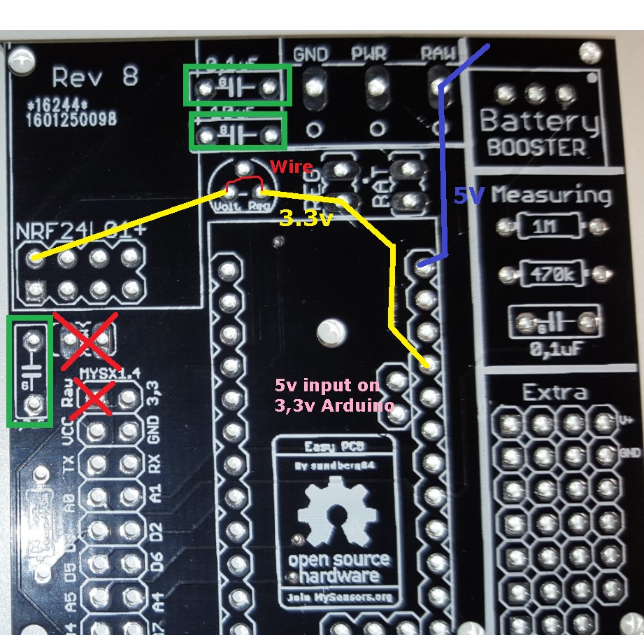
    The caps are not regulating anything - they are just smoothing everything out 🙂


  • @sundberg84 A picture is worth a 1000 words! Thanks for taking the time to do this for me. I don't have the 0.1uF or 10uF caps available but will order and add them. My real problem is that I am limited in the components I have on hand and have to order them so it takes a while (plus I'm anxious to work on this!).


  • Hardware Contributor

    @chuckconnors You can do it without the 0.1 and 10uF caps but it can generate some range issues and instability. The most important is 4.7 but I have nodes both working without 0.1 and 10uFcaps and nodes that completley failed without them.


  • I am doing the above (RAW with 5-7V on 3v minis). Would be great in a future revision to allow the bypass of the regulator. Also I jumped RAW to PWR and cut the trace from PWR so I could use a 2 pin header for power and ground 🙂


  • Hardware Contributor

    @chuckconnors I will think about how to bypass the voltage regulator, but anyway you need to solder something (either a jumper or voltage regulator). Do you have any tips?

    Good tip with the raw/pwr. If you have not cut the pcb you also have the proto area where the first is VCC (3.3) and second is Gnd.


  • @sundberg84 I was able to use your marked up image to successfully build two nodes without problem. Thanks again for the help with hooking things up and for providing the board for purchase as well. I was able to build the whole thing in about 10 minutes even with my limited soldering abilities.

    The only gripe I have is that one of my boards had a hole for the 4.7uF cap that wasn't completely drilled out. It was easy enough to just solder to the nearby ground. This is a dirtyboards quality control issue. I'm hoping not to see this on any of my other boards. I guess I'll have to inspect them before adding the components for future nodes.

    All the best to you!


  • Hardware Contributor

    @chuckconnors! Thank you for those kind words - it is appreciated.
    To save your node without the hole for 4.7uF you can solder it directly on the nrf if needed. I hope you have great use for the boards in the future.


  • @sundberg84 I'm about to make an aliexpress order and would like to get some voltage regulators. I scanned through the post but didn't see a BoM. Can you please tell me the part number for the voltage regulator used?


  • Hardware Contributor


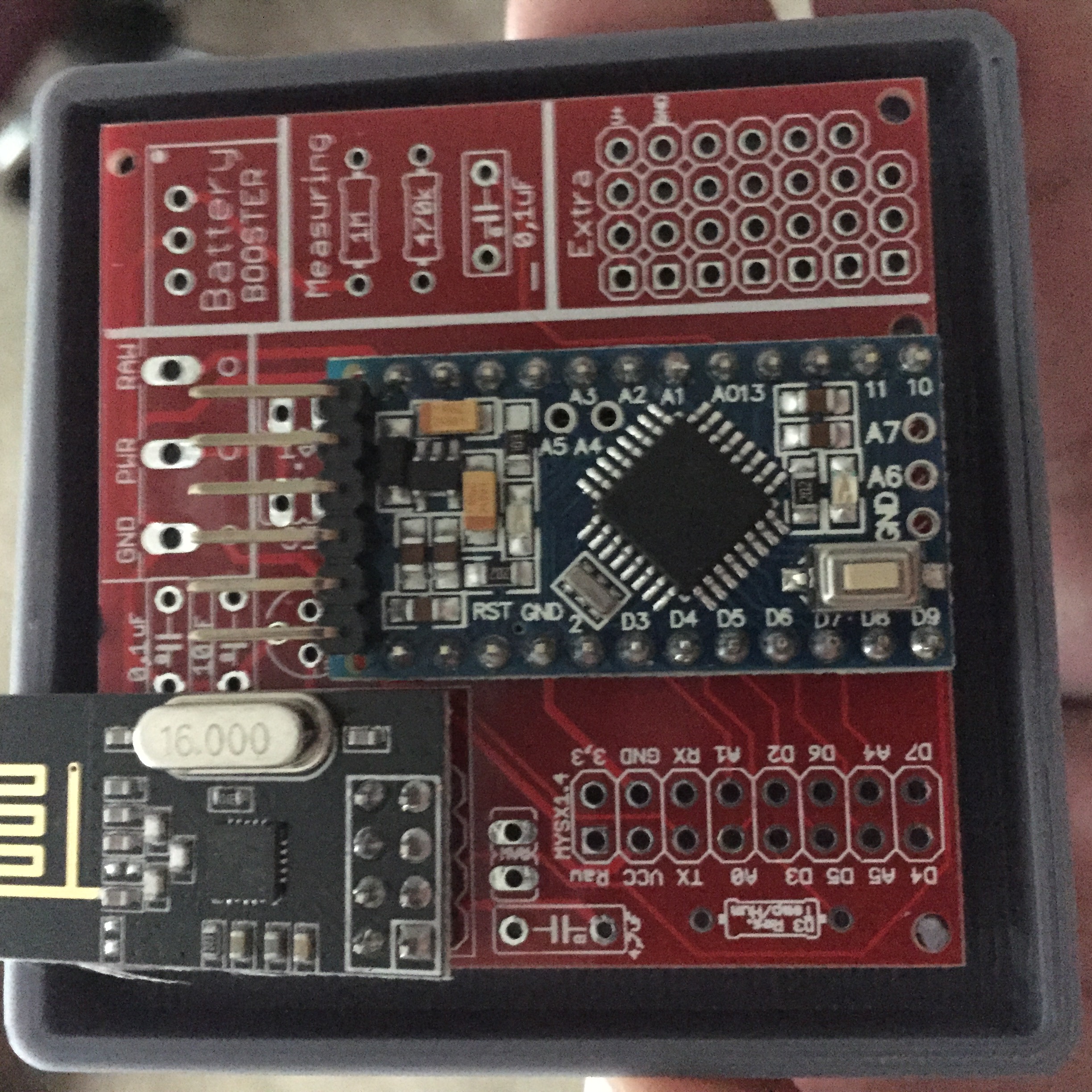
  • The boards have arrived!!! YES!!

    It took about 3 weeks between the shipping status and my mailbox. I guess I cant complain.

    0_1459186281454_IMG_0422.JPG

    @sundberg84 I do have another question.

    Are the pins A6, A7 and the extra ground (next to A6) connected at all? is it worth to solder a connector on them to the PCB?

    Edit: or maybe 2...
    D8 does not seem to be used, is this correct?

    Cheers


  • Hardware Contributor

    @barduino

    From the look of the design files, your are correct, A6 A7 and D8 are not connected. The GND pin is connected to the GND on the PCB, so just for the sake of ticking all the boxes, i would have that connected to the PCB from the Arduino.

    Wait for @sundberg84's confirmation on my details, but from what i understand my observations stated above are correct. As i say though, wait for Sundberg's confirmation. I wish you happy tinkering with yet another awesome contribution from Sundberg. 😉


  • Hardware Contributor

    @barduino A6 and A7 is not connected, but as @Samuel235 said - the ground is connected to the PCB with a line to ground source. There are three grounds connected from the arduino (I dont know why exactly) and they are all connected/wired on the PCB.


  • @Samuel235 , @sundberg84 , thank you both


  • @sundberg84
    Hi,
    The suppler has an similar product, is it usable for the same purpose?

    http://www.ebay.com/itm/5x-DC-2V-5V-3-3V-Boost-Buck-Converter-315M-433M-2-4G-RF-Wireless-Module-/181768067370?hash=item2a5238992a

    0.8-3.3V v. 2-5V ?
    thanks


  • Hardware Contributor

    @Barna Its possible to use this, but you want as low as possible and not 2V. This means using 2xAA (3v max) you only have a range down to 2V before the booster wont work anymore. At this point if you have not changed the fuses in the arduino it will fail. I guess you could use this with 3XAA (4.5V) as well if thats what you are aiming for.


  • @sundberg84
    ok, thanks. In that case some power will be left in the AAs, Am I right?
    what do you advice if I need 5V for some sensors but I would like to use battery?
    3xAA, 4xAA, 9V with regulator - is the lifetime of battery is efficient in this case ?


  • Hardware Contributor

    @Barna
    That is a hard question, because i try to do 3.3v for battery and 5v for regulated power.
    I have 1 node at this point running on a 9v battery and 5v arduino (motion detector) but without booster and battery measurment. I have removed led and at this point i have had it run for 4 weeks. I have NO clue about batterylife but I do not expect it to work pretty long.


  • mmmm i think that al this work, for a 4 weeks working sensor is not a good solution for a home automation system....
    Why can a Zwave or 433Mhz motion sensor work for more then a year...
    Is my biggest question..
    Forum link

    Is there relay now solution for a battery live for a year...
    Other bord, other sketch, other regulator, other battery...

    or...


  • @Dylano Google for low power arduino mini. Or arduino mini on battery. I've got one running now for half a year on two aaa batteries. Only lost 10% or something.
    (Quickest is to remove the led and the voltage regulator)


  • Hardware Contributor

    @Dylano Im not sure if I understand what you mean. This PCB does not support 433mhz or Zwave. You need to make that a question in the forum. I have nodes with this PCB now almost running for a year, and reporting good battery level.

    As Sander told you above, remove led and voltage regulator on a 3.3v arduino and you will run a mysensor node for a year:
    alt text


  • This post is deleted!


  • @Sander-Teunissen I have some rev6 that I am willing to sell. Let me know if you are interested.


  • If someone has one of these left in germany or nearby i'm willing to buy one for daugther-board dev purposes.


  • @sundberg84 said:

    I have nodes with this PCB now almost running for a year, and reporting good battery level.

    I see that battery measuring is not working in my case.
    Can you post your sketch for a DHT22 or dallas sensor? Because readVCC.h does not work with a step up booster and 2x AA batteries connected, it seems..


  • Hardware Contributor

    @lxz This is my code (Note dev branch!) for DHT22 incl battery measuring (2xAA).
    The reason for readVCC:h does not work is that you measure after the booster = always 3.3V!

    // Enable debug prints
    #define MY_DEBUG
    
    // Enable and select radio type attached
    #define MY_RADIO_NRF24
    //#define MY_RADIO_RFM69
    #define MY_NODE_ID 15
    
    #include <SPI.h>
    #include <MySensor.h>  
    #include <DHT.h>  
    
    #define CHILD_ID_HUM 0
    #define CHILD_ID_TEMP 1
    #define HUMIDITY_SENSOR_DIGITAL_PIN 3
    unsigned long SLEEP_TIME = 600000; // Sleep time between reads (in milliseconds)
    
    #define SKETCH_NAME "UtomhusHumSyd #15"                // Change to a fancy name you like
    #define SKETCH_VERSION "1.0"                    // Your version
    
    DHT dht;
    float lastTemp;
    float lastHum;
    boolean metric = true; 
    MyMessage msgHum(CHILD_ID_HUM, V_HUM);
    MyMessage msgTemp(CHILD_ID_TEMP, V_TEMP);
    
    //=========================
    // BATTERY VOLTAGE DIVIDER SETUP
    // 1M, 470K divider across battery and using internal ADC ref of 1.1V
    // Sense point is bypassed with 0.1 uF cap to reduce noise at that point
    // ((1e6+470e3)/470e3)*1.1 = Vmax = 3.44 Volts
    // 3.44/1023 = Volts per bit = 0.003363075
    #define VBAT_PER_BITS 0.003363075  
    #define VMIN 1.9                                  //  Vmin (radio Min Volt)=1.9V (564v)
    #define VMAX 3.0                                  //  Vmax = (2xAA bat)=3.0V (892v)
    int batteryPcnt = 0;                              // Calc value for battery %
    int batLoop = 0;                                  // Loop to help calc average
    int batArray[3];                                  // Array to store value for average calc.
    int BATTERY_SENSE_PIN = A0;                       // select the input pin for the battery sense point
    //=========================
    
    void setup()  
    { 
     analogReference(INTERNAL);             // For battery sensing
    
      delay(500); // Allow time for radio if power used as reset
      
      dht.setup(HUMIDITY_SENSOR_DIGITAL_PIN); 
    
      metric = getConfig().isMetric;
    }
    
    void presentation()  
    { 
      // Send the Sketch Version Information to the Gateway
     // Send the Sketch Version Information to the Gateway
      sendSketchInfo(SKETCH_NAME, SKETCH_VERSION);
    
      // Register all sensors to gw (they will be created as child devices)
      present(CHILD_ID_HUM, S_HUM);
      present(CHILD_ID_TEMP, S_TEMP);
    }
    
    void loop()      
    {  
      delay(500); // Allow time for radio if power used as reset
      delay(dht.getMinimumSamplingPeriod());
     
      // Fetch temperatures from DHT sensor
      float temperature = dht.getTemperature();
      if (isnan(temperature)) {
          Serial.println("Failed reading temperature from DHT");
      } else if (temperature != lastTemp) {
        lastTemp = temperature;
        if (!metric) {
          temperature = dht.toFahrenheit(temperature);
        }
        send(msgTemp.set(temperature, 1));
        Serial.print("T: ");
        Serial.println(temperature);
      }
      
      // Fetch humidity from DHT sensor
      float humidity = dht.getHumidity();
      if (isnan(humidity)) {
          Serial.println("Failed reading humidity from DHT");
      } else if (humidity != lastHum) {
          lastHum = humidity;
          send(msgHum.set(humidity, 1));
          Serial.print("H: ");
          Serial.println(humidity);
      }
      batM();
      sleep(SLEEP_TIME); //sleep a bit
    }
    
    void batM() //The battery calculations
    {
       delay(500);
       // Battery monitoring reading
       int sensorValue = analogRead(BATTERY_SENSE_PIN);    
       delay(500);
       
       // Calculate the battery in %
       float Vbat  = sensorValue * VBAT_PER_BITS;
       int batteryPcnt = static_cast<int>(((Vbat-VMIN)/(VMAX-VMIN))*100.);
       Serial.print("Battery percent: "); Serial.print(batteryPcnt); Serial.println(" %");  
       
       // Add it to array so we get an average of 3 (3x20min)
       batArray[batLoop] = batteryPcnt;
      
       if (batLoop > 2) {  
         batteryPcnt = (batArray[0] + batArray[1] + batArray[2] + batArray[3]);
         batteryPcnt = batteryPcnt / 3;
     
       if (batteryPcnt > 100) {
         batteryPcnt=100;
     }
     
         Serial.print("Battery Average (Send): "); Serial.print(batteryPcnt); Serial.println(" %");
           sendBatteryLevel(batteryPcnt);
           batLoop = 0;
          }
         else 
         {
         batLoop++;
         }
    }```


  • Hi

    I also bought v8 of these boards. 2 sensors up an running perfect.

    2 others modules on the other hand, I think I fried the arduino. I am using 5v mini's. They worked when programming thru the USB port. Also communication with domoticz. They stopped working when I attached the 6v external adapter. I connected these to the ground and power connector. Now lights go on, but nothing anymore also not on the serial monitor.

    Should I have used the raw connector????

    thanks for helping


  • Hardware Contributor

    Short answer - yes you should have used RAW. But at least you learned a lesson if you want to think positive. ☺

    Try and see what happens if you change. Maybe they are still OK.


  • thanks!, lessons learned indeed. . Great stuff though.


  • what size terminal blocks do you buy? I bought some and they are the wrong size.


  • Hardware Contributor

    @scooter217, from a quick inspection of the .brd file and a look around the internet for the datasheets it would seem that sundberg has allowed for any screw terminal block that uses a 5mm pin pitch. So you would need a 3 terminal 5mm pin pitch screw terminal. Please allow @sundberg84 some time to reply to ensure I am correct.


  • Hardware Contributor


  • @sundberg84 Thank you, just ordered some from ebay!


  • Hi Sundberg.
    First of all thanks for what you have done here, and hi from New Zealand.
    I have a problem though, sorry to be a hassle.
    I assembled my first board tonight and I dont get 3.3v across the NRF. It starts at 0.07V then falls down to 0 on my cheap meter. Same on the MYSX1.4 connector at 3.3 and gnd. Am getting 3.3 on the mini as well as VCC and GND on the MYSX area so the regulator is working. May be a short? Or a bad solder? Although they look good to me.... If so what solder joints should I redo? Any other ideas?
    Also, Ive traced back the VCC from the NRF and I cant see where it connects to a power source, either the battery in or the boost converter?
    0_1461234488858_MS.jpg

    Thanks,
    Matt


  • Hardware Contributor

    @Matt Hi Matt - tnx.

    Try to measure here: whats your reading?
    0_1461234892945_1.jpg
    if its 3.3v its your radio thats has some error... this is prettu much the last point before radio. Also measure VCC/GND under the pcb and not on top, what does it say?

    Sounds like a short or bad solder...


  • @sundberg84
    Ah crikey I think Im being thick, I just put a jumper across BAT connectors after tracing the lines and reading the manual, am now getting 2.8 at the NRF. Sorry for being a numpty. Still not picking up on my gateway, time to go to bed but will get the serial monitor running tomorrow....
    Thanks for the quick reply.


  • Finally got my boards. In color: Yellow.
    If I would skip the Booster is the esiest thing to just wire Vi - Vo?

    0_1462250321694_IMG_4703.JPG


  • I have a question about using this board as a gateway. Pinout of Mini Pro and Nano are almost identical. I built an adapter board to plug in a Nano into this board. Pin by pin control shows it is OK. I checked connectivity with MYSController. The gateway boots up. When I turn on my battery powered sensor, it asks for ID, the gateway "supposedly" sends it. I watch this from the messages. The sensor does not register. It asks four more times, the gateway responds four times. But sensor could not be ID'd and of course registered.

    I am thinking either reception problem on sensor side, or transmission problem on gateway side? Could it be a power problem related with design of the board? Is there any way to identify?

    Thanks


  • Hardware Contributor

    @Valle - yes you can just put a wire between left and right pin - but it wont work for a long time (the pro mini will die when battery goes below 3v i think).

    @nunver - I have never used this board as gateway. What does your controller say, does it apply an ID for the request?


  • @sundberg84

    I'm using mfalkvidds Plant monitoring
    mfalkvidd said:

    An update on battery life: The sensor in my bonsai tree has been reporting every 11,5 minutes since 2015-11-07, so over the last ~four months it has done 24,504 measurements. The battery level has gone from 3.187V to 3.142V, which means a drop of 0.01125V per month. Assuming I let it go down to 2.34V (limit for 8MHz according to the datasheet) and that the voltage drop is linear, I should get (3.187-2.34)/0.01125 = 75 months = ~6 years. There are several error sources in this calculation, but it looks like battery life will be quite good, even though the sensor reports much more often than necessary.

    So I will try without Booster. But for other sensors I will use booster.


  • Hardware Contributor

    @Valle said:

    So I will try without Booster. But for other sensors I will use booster.

    Sounds good - let us know how it works out for you. 2,34V is for a genuine Arduino so you know - I dont think a clone manages that... also the last energy (from 1,9 to 2,34v) is not used even though the radio could handle it if you used a booster.


  • Hero Member

    Thanks @sundberg84 for this little board. I have just completed a sensor to monitor the state of our 12v house solar power supply.

    It uses an ACS712 Hall Effect Current Sensor Module to keep track of amps in and out of the battery. A voltage sensor to check battery levels and two DS18b20 temp sensors to monitor battery temp and ambient area temp. It reports back to our Domoticz server.

    0_1462273371700_board.jpg

    0_1462273409712_dom.jpg


  • @sundberg84 yes it gives an ID of 1, but somehow sensor keeps asking four more times. At the end of the cycle, no ID is set. So no sensor shown.


  • Hardware Contributor

    @nunver said:

    @sundberg84 yes it gives an ID of 1, but somehow sensor keeps asking four more times. At the end of the cycle, no ID is set. So no sensor shown.

    What does the log node say - find parent?
    This sounds like either software issue or most probably radio range/power issue,


  • Hello, I'm just finished with 3 cards and test . I read on mysensor.org I'll connect NRF24L01+ Radio whit decoupling capacitor of 47µF and on your card whit 4,7µF

    What is the difference?


  • Mod

    @Affe in practice, there is usually no difference. 4.7uF is enough, but 47uF doesn't hurt.


  • Hardware Contributor

    Hello,

    I just ordered from DirtyPCB.
    Thank you very much for this board which will obviously save me a lot of time with the radio connection.
    I'm planning to use the boards for :

    • as door+temp/humidity sensors for my children's bedrooms, not for the "security"/"safety" aspect but to manage AC more efficiently
    • as window sensors for all windows in my appartment coupled with a rain sensor on the balcony, so I can ring an alarm/flash something/sens sms if it starts to rain and one of the windows is left opened. I'm in a tropical country and windows are opened most of the time, with the sudden and strong rains and winds we have sometime it can really be ugly 🙂

    Power will most probably come from button cells and I will cut the right part of the PCB to fit in small and very cheap plastic boxes I find in shops here. I'm just waiting to see if the test sensor I have put on my entry door survives long enough with a CR2032.


  • Could you give me the size when the pcb is fully soldered as battery sensor?


  • Hardware Contributor

    @Nca78 - sounds great, let me know how it works out for you! Good luck!

    @Rasenheizung - 50x50cm fully soldered. The dept is about 35mm (Batteryholder + PCB + Components)


  • Hardware Contributor

    So - I have a question for the community about boosters. I had a 3.3v Arduino running with my PCB. The radio is connected directly to the battery and the rest through a booster. I experienced alot of st:fails.

    0_1467277885161_1.png

    I tested adding a 0.1uF cap on the booster from OUT to GND and the st:fails became st:ok, even though the radio does not get its power from this booster.

    Im sure the boosters are in different qualities and renders alot of noice - but could it effect the radio - through the arduino?
    If this continues Im going to add the possibility to add this cap on my PCB. (Or maybe its possible to use 0.1uF cap by the voltage divider...)

    Any feedback ?


  • @sundberg84 typically, I try to add the lc-filter to the booster as some of them are very noisy. This is very simple - 3.3µH Axial lead inducter and a large 220µF capacitor (I use the SMD version). This helps to smooth any ripple effect.


  • Hardware Contributor

    Any sort of manipulation, including regulators and boosters, added to any module i would always attempt to filter and smooth the input AND the output of the devices. The noise from the boosters would technically be reaching your radio from those traces. I'm not sure if a diode would stop it from feeding back to the radio, but either way if it did i would still prefer to smooth and filter the power instead of stopping it coming backwards.


  • Hardware Contributor

    @sundberg84
    it could be multiple things..
    But as alexsh1 said you can try to fix it with filtering.

    You can usea capa + an inductor or a ferrite bead too (a bit different), or a small resistor too can work like a snubber in fact. Generally 0-2ohms<100ohms, but the smaller the better depending of the capa too because it could generate drop out voltage. So for ferrite, it's the same, it's better to use a low ferrite res.
    But then, with filtering come some compromise regarding the booster efficiency and the load etc... Use formula and calc or the scope or iterate to choose the better compromise. But that should fix it mostly.

    There are two main strategy:

    • you filter each power input of concerned ics,
    • or you filter at powersupply (booster) output because lack of footprint on pcb.

    Note :

    • it's better for filtering to use small multilayer ceramic capa. low esr, low esl when you can, but again there can be some compromise in this.
    • shielded inductor on the booster module is better
    • if high esr and esl capacitor used at booster input, then you can have noise back into the batterie, and then propagate elsewhere. If it's your case, and can't fix it at power supply input, try to filter at your radio vcc input with another res for instance and a capa
    • there is also the ground loop, having a strong gnd, is better. this is one point why it's useful to use gnd pour plane on your pcb.
    • etc...

    I hope this will help you a bit 😉


  • Hardware Contributor

    Boards received from DirtyPCB, they look gorgeous in white, too bad I have to put those ugly blue nrf and promini boards on top of it 😛
    I received exactly 10, they are looking good except the silkscreen 1/2mm too much on the left for some of the boards


  • Hardware Contributor

    @sundberg84 sorry to bother you but maybe you have an idea.
    I soldered components as in the picture below (looking so much cleaner than with all the cables...), I am using a 3.3V pro mini.
    Before soldering I tested the pro mini and the nrf24 together, connected with cables, and simulated the reed switch with some wires: everything was fine and I was receiving the open/close messages in domoticz.
    I soldered the components as below but I only got some "radio init failed" when connected to my PC, power coming to the GND/VCC on top of the arduino.
    As I put the jumper on "reg" to bypass the regulator, my understanding is that in this case the raw/power/vcc are all connected together, am I wrong ?

    Another subject, I suffered to cut the right part of the PCB with a cutter, would it be possible to add some slots along the black line to reduce a bit the length we have to cut ?

    alt text


  • Hardware Contributor

    @Nca78, do you have power on the radio, do you have power present everywhere it should be? Arduino included. If this is all present i would then go into diode mode with a multimeter to make sure all of your pins on the radio are connected to those of the ATMega328 on the arduino.

    This would be just a basic starting point at troubleshooting this.


  • Hardware Contributor

    @Nca78 - Hi, nice to see your white boards ! 🙂
    I see your image, and you have choosen a REG jumper (regulated power supply). How do you power it? Through RAW?
    You have missed the voltage regulator with caps for the radio, so at this point it does not get any power at all?

    If you are using a 3.3v arudino with RAW you can bypass it with a wire.
    If you are using a 5v with RAW or Regulated power (PWR) you need a 5 to 3.3v voltage regulator.


  • @sundberg84
    @BastienVH said:

    @sundberg84 said:

    If you use the FTDI connector, make sure its the 3.3v and connect it to Gnd/Pwr on the PCB and not Arduino FDTI connector.
    You could just exclude those pins and connect a battery directly and use that as power and the FDTI as programmer/serial debug only

    Bat or Reg is nessecary!
    See this picture for battery use: https://www.openhardware.io/view/4/EasyNewbie-PCB-for-MySensors
    https://www.openhardware.io/uploads/568ed84b60aa3f8965fbf095/image/3.jpg
    All components in the image is needed (except battery measurment).
    If you dont want to use booster you need to bypass that one with a wire/jumper (or set the jumper on REG instead of BAT but that kills the logic).

    The battery doesnt "need" the 0,1uF but see here:https://www.mysensors.org/build/battery
    "The tap point could be bypassed with a 0.1 uF capacitor to keep the noise level low, at this otherwise high impedance point. "

    Hi. I've been using this board with 5V power from cell chargers and it works great. I'm trying to make my first battery sensor and am a bit confused (again) as to what is necessary. I'm powering using 2 AA batteries. I've cut the right side off the board so I'm obviously not using the measuring portion, but the above bit about the booster leaves me confused. Can someone answer:

    • I connect via the PWR and GND pads right?
    • Do I jumper BAT or REG?
    • Do I need to do anything else to get this to work?

    I tried to program using battery in but was using the ground from the ftdi connector. I could not get this to work. I'm thinking that this was a major problem and that I should have used the battery ground. That's the right approach right?


  • Hardware Contributor

    @chuckconnors - assuming you are using a Arduino Pro Mini 3.3v it will die when the voltage drops below 3v (about) so it leaves alot of power left in your batteries and also it will die rather quickly.

    Thats why I have designed the PCB with a booster for battery operations, and then its not possible to cut the right side of the PCB since the booster is located there. Check the image out: https://www.openhardware.io//uploads/568ed84b60aa3f8965fbf095/image/Rev8 Bat.jpg and you see the booster on the top right corner.


  • Hardware Contributor

    Thank you for the tip @sundberg84, it just needed the bypassing of the regulator, and then I can connect my cell battery to the GND and PWR and it runs fine.

    @Samuel235 yes you are right I did it and it didn't have Vcc power that's why I asked that question to sundberg84, next time I'll precise it as it could have ended in wasted time...

    @chuckconnors this is how you have to connect the jumpers to use directly on battery power (on GND and PWR pins). But as sundberg84 says you will not have a long battery life with AA batteries and without a booster. Even if you update the fuses and bootloader to run at 1MHz and have the BOD at 1.8V there will still be power left (I guess not far from 25% of capacity with 2 batteries) that is wasted. If you keep the defaults settings of the arduino at 8MHz it will run down to 2.4V and around half of the energy in your batteries will be wasted.


  • @sundberg84 is the board ready for Ver 2.0.0 ?
    the final version announced yesterday at HERE, anyhow can you share an example of Node sketch ?


  • Hardware Contributor

    @Lior-Rubin - the PCB or the hardware has nothing to do with 2.0
    It will work fine - 2.0 is only software (what you program it with).
    I have been running 2.0 beta (dev) for a long time now without any problems.


Suggested Topics

21
Online

11.2k
Users

11.1k
Topics

112.5k
Posts