💬 Easy/Newbie PCB for MySensors
-
@genuinejd - can you post a picture of your pcb? Might be easier.
If you have a multimeter, you can measure the input and output of the booster.@sundberg84 I meant to post a picture, then last night I discovered my issue. I soldered all the components except the pro mini! Once I did that, everything started working. I did discover that mys was reporting "No potential parents replied to find parent request." Once I changed my radio cap from 4.7 to 47 it started sending messages immediately.
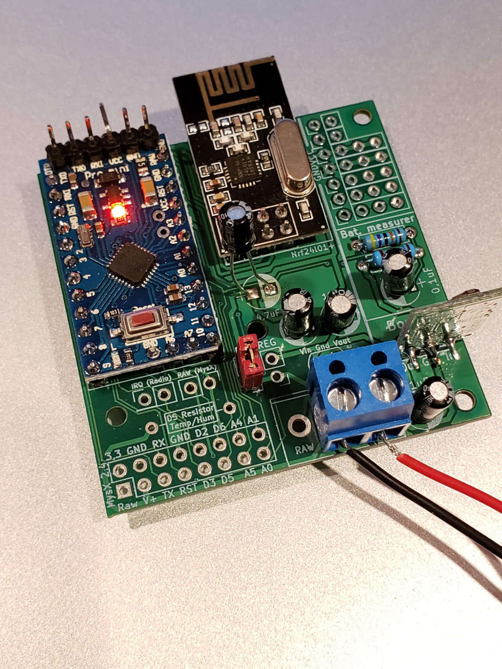
Here's my first node (I haven't removed components from the pro mini yet for extended battery life), with bare minimum components in all it's battery-powered newbie glory!
Thanks!
-
@sundberg84 I meant to post a picture, then last night I discovered my issue. I soldered all the components except the pro mini! Once I did that, everything started working. I did discover that mys was reporting "No potential parents replied to find parent request." Once I changed my radio cap from 4.7 to 47 it started sending messages immediately.
Here's my first node (I haven't removed components from the pro mini yet for extended battery life), with bare minimum components in all it's battery-powered newbie glory!
Thanks!
@genuinejd - Nice work! Thanks for reporting back! :)
-
@genuinejd - Nice work! Thanks for reporting back! :)
@sundberg84 So as it turns out, it worked great for about a day while I was letting it run to test battery life. Suddenly my gateway was not receiving any messages from my node.
- I checked all the caps, the booster, etc.
- I tried a few different caps for the radio up to 100uF
- The voltage on the radio matched the voltage from the battery.
- I tried switching to the REG jumper and wiring across the voltage regulator, the radio was then getting 3.3v from the booster, but still no communication between the node and gateway
- I also tried using my bench power supply for reg 3.3v.
Strangely, the ONLY thing that worked was when I used the 5v post on my bench power supply (with the BAT jumper, no voltage converter)
I have not yet tried swapping out the radio since it works with 5v, but I'm unsure what to try next. I have 6 other mys nodes communicating with my gateway with no problems and greater distances (all using nanos).
Any suggestions? Apologies if this doesn't sound like an issue with the board, I can post in the troubleshooting forum if you think it's a radio problem.
-
@sundberg84 So as it turns out, it worked great for about a day while I was letting it run to test battery life. Suddenly my gateway was not receiving any messages from my node.
- I checked all the caps, the booster, etc.
- I tried a few different caps for the radio up to 100uF
- The voltage on the radio matched the voltage from the battery.
- I tried switching to the REG jumper and wiring across the voltage regulator, the radio was then getting 3.3v from the booster, but still no communication between the node and gateway
- I also tried using my bench power supply for reg 3.3v.
Strangely, the ONLY thing that worked was when I used the 5v post on my bench power supply (with the BAT jumper, no voltage converter)
I have not yet tried swapping out the radio since it works with 5v, but I'm unsure what to try next. I have 6 other mys nodes communicating with my gateway with no problems and greater distances (all using nanos).
Any suggestions? Apologies if this doesn't sound like an issue with the board, I can post in the troubleshooting forum if you think it's a radio problem.
@genuinejd - the radio can not work with 5v, sorry but this might destroyed your radio. Do you have any serial debut for your node? Can you see what it does? It might be alot of different things, maybe the booster. In many times I have seen bad boosters which introduces noice and makes the radio go crasy.
-
@genuinejd - the radio can not work with 5v, sorry but this might destroyed your radio. Do you have any serial debut for your node? Can you see what it does? It might be alot of different things, maybe the booster. In many times I have seen bad boosters which introduces noice and makes the radio go crasy.
@sundberg84 I know that everything I've read says the radio cannot use 5v, but when hooked up to my bench power supply and connecting my multimeter leads to the NRF24L01+, it says it's getting 5v AND it's the only scenario where the node can successfully find the gateway and send/receive data.
I tried swapping out the radio and it was the exact same scenario. I'm getting NACK debugging messages on the gateway when it's trying to accept the node as a child. The only thing I haven't tried is replacing the booster.
For the moment, I wired up a second node with all new components and (after remembering to solder everything) it connected to the gateway right away. It's been running for about 30 minutes, so I'll post back after a time when I know if it will stop working or run until the batteries drain completely.
Side note: thanks for making such an awesome board!
-
Hi,
I build a node using an easypcb rev 10 for the rfm69. I am trying to connect two door sensors to the node using pins 2 and 3. The sensor on pin 3 works flawlessly, but the one on 2 doesn't (I'd like to use the interrupts to save power).
I saw that the Nrf24l01+ version has disabled pin 2, is that the case with the rfm69 version too? If yes, is there any way to use two different pins for interrupts? I need to know which sensor has been triggered so I can't connect them in series.
Thanks for the help!
@kiesel sorry for the late reply. Did you solve it ?
-
Is there a .sch version of the schematic that I can import into Diptrace? I can only find a .pdf
@Woodside all files should be posted @ openhsrdware.io. Is this some special file?
-
@kiesel sorry for the late reply. Did you solve it ?
@sundberg84 I did, thanks, I discovered ISRs. Thanks for the support.
-
@Woodside all files should be posted @ openhsrdware.io. Is this some special file?
@sundberg84 The only file type I can find on openhardware.io for the schematic is a pdf. DIPTrace is a schematic and PCB layout tool and uses .sch format for the schematic files. It cannot import a schematic layout from a pdf.
I was hoping to use DIPTrace to update the schematic for my projects using the EasyPCB and then transfer the result onto the board.
-
@sundberg84 The only file type I can find on openhardware.io for the schematic is a pdf. DIPTrace is a schematic and PCB layout tool and uses .sch format for the schematic files. It cannot import a schematic layout from a pdf.
I was hoping to use DIPTrace to update the schematic for my projects using the EasyPCB and then transfer the result onto the board.
@Woodside - you are correct, I have forgotten to update the Kicad Files. I have uploaded them all now - but... when I last made changes to these I upgraded from Kicad 4 to Kicad 5 which created some rescue/convert files. This made things very confusing with all the files and some things was not working properly if you didnt have all rescue files. There is a sch file - I hope it works for you.
-
@Woodside - you are correct, I have forgotten to update the Kicad Files. I have uploaded them all now - but... when I last made changes to these I upgraded from Kicad 4 to Kicad 5 which created some rescue/convert files. This made things very confusing with all the files and some things was not working properly if you didnt have all rescue files. There is a sch file - I hope it works for you.
@sundberg84 Thankyou
-
Is there a video of how to solder the signing chip? Because from what I can see there is a connection to be made right in the middle of the chip and I am not sure how to.
@kiesel - sorry, no video of this available at the moment. I made one some time ago but my HD crashed so I lost all my video of a project i made with signing. Maybe I have some left on the videocamera - I will check tonight.
What do you mean with "connection in the middle"? I know there was a fault in the old gerbers with D6 not connecting to the arduino but this was fixed in May so if you have new boards it should be fine. Make a continuity test from SCK (Pin6 on signing chip) to D6 on the arduino.
-
Is there a video of how to solder the signing chip? Because from what I can see there is a connection to be made right in the middle of the chip and I am not sure how to.
@kiesel It is a SOT23 if I remember correctly. There are only 3 pins, no pad underneath so soldering should be easy.
Perhaps the copper you see is part of a ground plane? It will not connect to the signing chip in any case.Do you feel secure today? No? Start requiring some signatures and feel better tomorrow ;)
-
@kiesel It is a SOT23 if I remember correctly. There are only 3 pins, no pad underneath so soldering should be easy.
Perhaps the copper you see is part of a ground plane? It will not connect to the signing chip in any case.@Anticimex @kiesel - yes, you are right - i mixed it up with the flash chip. Signing should be good - no issues reported (i have had several boards myself working fine).
-
Thanks for the help, I think I was looking at the wrong chip. The one I considered byuing had 6 legs, not only 3. I was thrown off by the easypcb having what appears to be 7 soldering points in the signing area.
-
Thanks for the help, I think I was looking at the wrong chip. The one I considered byuing had 6 legs, not only 3. I was thrown off by the easypcb having what appears to be 7 soldering points in the signing area.
-
I'm not sure if this is the right place to ask. But it seems right to me :)
Hi I have e few of the Easy/Newbie-pcb working for some time with good effort. One of them even in a shed at 20 - 25 meters in the garden which is fairly good isolated. Sending Temp/Hum/battery level. And the Gateway is in the house on the first floor behind a door in a wardrobe.Now I have a second shed which is behind the fist shed. Also very good isolated. The pcb I have in there is not reaching the gateway (it did before until the battery was empty).
Can I have the pcb in the first shed also working as an extender, so the second pcb will be able to send out topics to the gateway as well? What to add to my code to achieve that?