💬 Easy/Newbie PCB for MySensors
-
@fisher as @sven said - it might be a issue with your nrf... i have seen this issues in several forum posts.
Also, you can try to add a wire from nrf ground to scource ground (and/or try same from voltage regulator) to strengthen your ground connection.@barduino Asuming you are using 5v arduino and using RAW you add a voltage regulator (3.3v) to the radio. You do not need any jumper.
The voltage divider only works from PWR input but if you make a wire from PWR to Vin (right hole) on the booster this should work fine with the voltage divier.The internal voltage regulator can handle 3.35 -12 V (3.3V model) or 5 - 12 V (5V model). Below this the regulator will fail, so you need to set your battery measurment to 0 % 5v 100% = 9v.
This has not been tested by me yet on rev 8 so please share your findings.
Thanks @sundberg84
-
It took a while, but I received the rev8 boards last week. I have already had some time to play with it and it works perfectly on 2x AA. Thanks for sharing your pcb design @sundberg84
-
@chuckconnors Well, it is possible... you can always hard wire/bypass stuff with wires... its possible.
See @BastienVH for minimun req. 3.3v. In bat. operations you feed the radio directly from batteries - less noice and radio can handle down to 0.9V (i think) so its not a problem. You need the booster for sensors and arduino requiers 3.3v to run. You can also feed 3.3v directly to VCC on the PCB if you have that regulated. Then you can just add jumper to reg.If you tell me exactly what you want to do i can help you and explain what you need and how to wire it. With your setup now like you described and you run that on 3v batteries it will be dead within a week.
If you want battery power - you should go with 3.3v arduino (advantage: last longer)
If you have regulated 5v (like from a phone charger) use 5v arduino (advantage: smaller PCB)@sundberg84 said:
@chuckconnors Well, it is possible... you can always hard wire/bypass stuff with wires... its possible.
See @BastienVH for minimun req. 3.3v. In bat. operations you feed the radio directly from batteries - less noice and radio can handle down to 0.9V (i think) so its not a problem. You need the booster for sensors and arduino requiers 3.3v to run. You can also feed 3.3v directly to VCC on the PCB if you have that regulated. Then you can just add jumper to reg.If you tell me exactly what you want to do i can help you and explain what you need and how to wire it. With your setup now like you described and you run that on 3v batteries it will be dead within a week.
If you want battery power - you should go with 3.3v arduino (advantage: last longer)
If you have regulated 5v (like from a phone charger) use 5v arduino (advantage: smaller PCB)@sundberg84 I just got my boards in and am hoping to hook things up this weekend for a simple Temp/Humidity node with a DHT11. The plan is to provide 5V input from an old phone charger. I'd like to wire this directly to the arduino via the GND PWR pads at the top. What jumper do I need to set for this?
Can I just power the radio through the 4.7uF cap via the 3.3V and ground pads on the left side of the board via some wires? Does the radio already have a ground coming from the ground on the arduino? I'm assuming that power would be coming from the arduino regulator. Will this set up work?
Thanks again for your patience.
-
@chuckconnors - great weekends plan :+1:
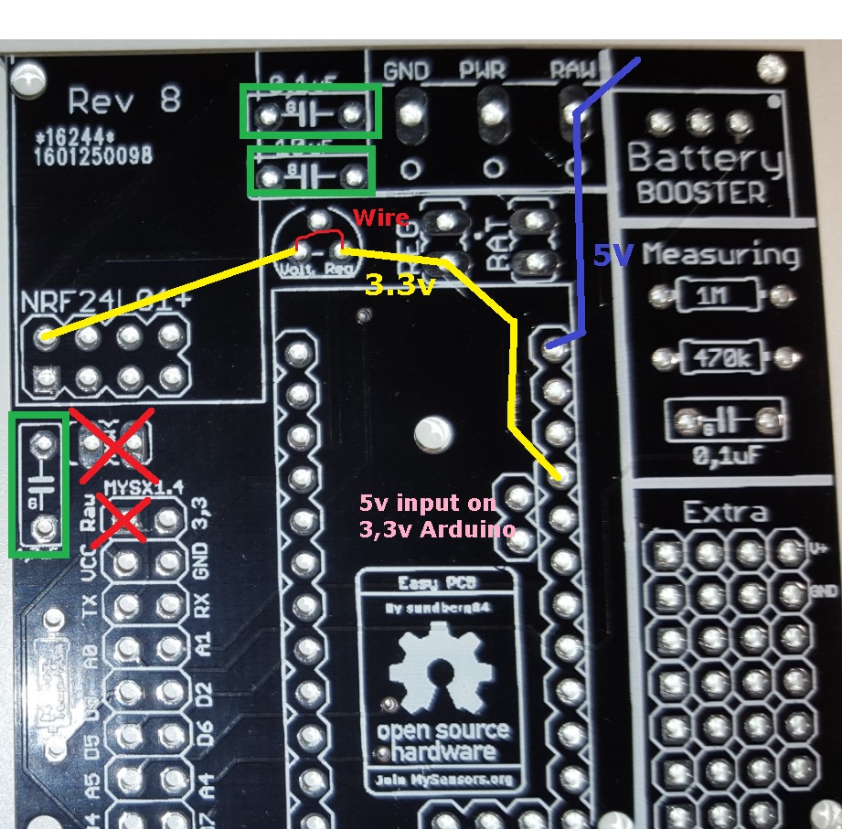
Im suspecting you are going to run a 3.3v pro mini?The PCB is designed so if you want to input 5v you set the REG jumper, use a 5v pro mini and use a external voltage regulator for the radio - see here!
If you are planning to use a 3.3v arduino and power it with 5v you need to input power to RAW and wire a connection/bypass on the voltage regulator. This is not the main design for the PCB but should work. What you need to know is that pro mini internal voltage regulator is not as good as an LE33AC in my world so there might still be great value of using the 0.1 and 10uF caps on power to radio.
Ground from Radio always goes straight to ground scource, not Arduino Pro mini.
-
@chuckconnors - great weekends plan :+1:
Im suspecting you are going to run a 3.3v pro mini?The PCB is designed so if you want to input 5v you set the REG jumper, use a 5v pro mini and use a external voltage regulator for the radio - see here!
If you are planning to use a 3.3v arduino and power it with 5v you need to input power to RAW and wire a connection/bypass on the voltage regulator. This is not the main design for the PCB but should work. What you need to know is that pro mini internal voltage regulator is not as good as an LE33AC in my world so there might still be great value of using the 0.1 and 10uF caps on power to radio.
Ground from Radio always goes straight to ground scource, not Arduino Pro mini.
@sundberg84 Thanks for the information. So the 5V source goes to RAW input and this goes to the RAW jumper on the left portion of the board. I need to jump that to complete the connection to get RAW power to the Arduino, right? From there it looks like the 3.3V connects to the 4.7uF cap and the power on the radio so I'm assuming once RAW power is supplied to the Arduino that I'd start getting 3.3V output from the 3.3V pin on the Arduino. Am I reading the traces wrong?
Thanks again
-
@chuckconnors Hi! Dont mind the RAW jumper, this is a future/requirement for MysX connector and is only used if you want RAW power to the connector to the left. Put 5v to the top right RAW input.
The caps are not regulating anything - they are just smoothing everything out :)
-
@chuckconnors Hi! Dont mind the RAW jumper, this is a future/requirement for MysX connector and is only used if you want RAW power to the connector to the left. Put 5v to the top right RAW input.
The caps are not regulating anything - they are just smoothing everything out :)
@sundberg84 A picture is worth a 1000 words! Thanks for taking the time to do this for me. I don't have the 0.1uF or 10uF caps available but will order and add them. My real problem is that I am limited in the components I have on hand and have to order them so it takes a while (plus I'm anxious to work on this!).
-
@chuckconnors You can do it without the 0.1 and 10uF caps but it can generate some range issues and instability. The most important is 4.7 but I have nodes both working without 0.1 and 10uFcaps and nodes that completley failed without them.
-
@chuckconnors I will think about how to bypass the voltage regulator, but anyway you need to solder something (either a jumper or voltage regulator). Do you have any tips?
Good tip with the raw/pwr. If you have not cut the pcb you also have the proto area where the first is VCC (3.3) and second is Gnd.
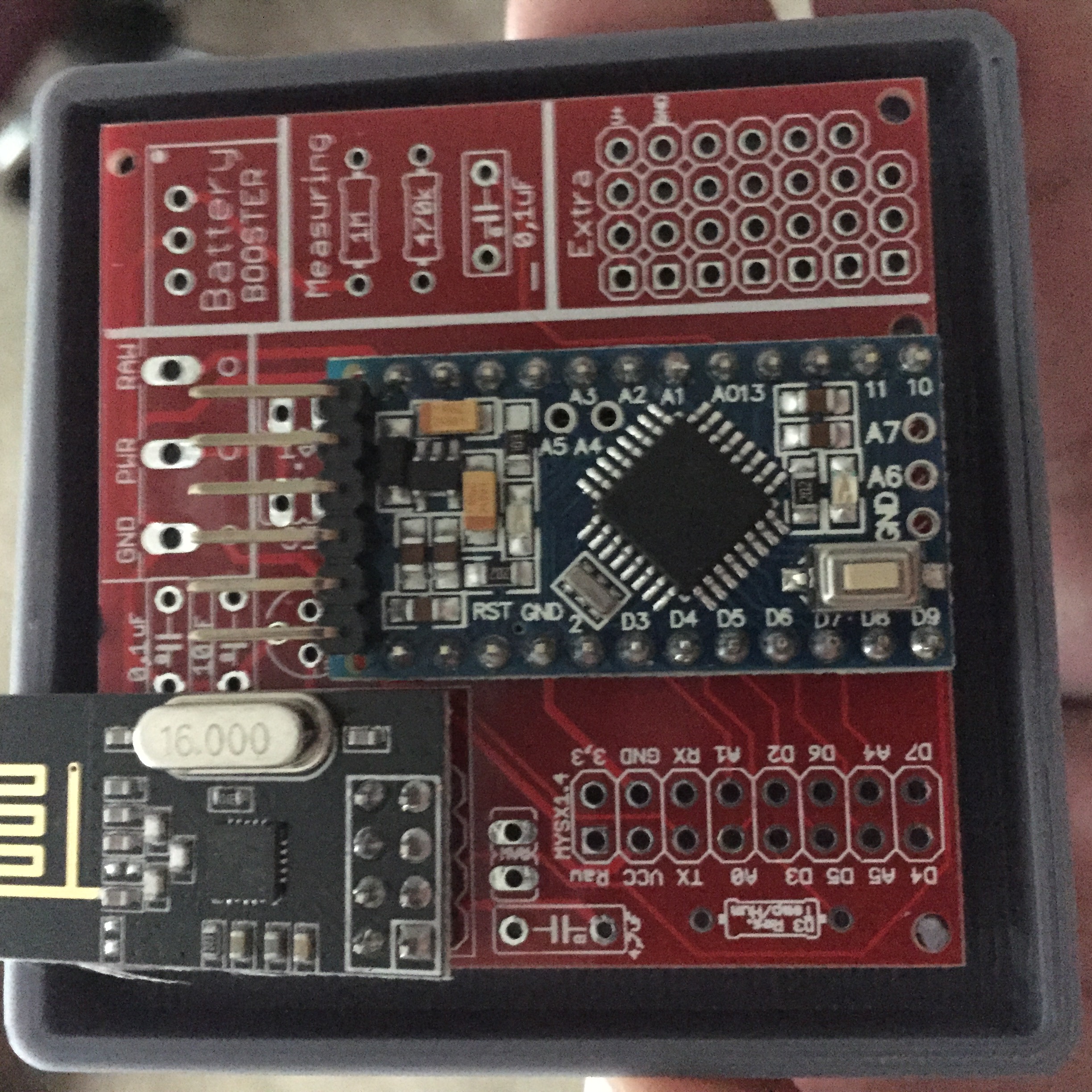
@sundberg84 I was able to use your marked up image to successfully build two nodes without problem. Thanks again for the help with hooking things up and for providing the board for purchase as well. I was able to build the whole thing in about 10 minutes even with my limited soldering abilities.
The only gripe I have is that one of my boards had a hole for the 4.7uF cap that wasn't completely drilled out. It was easy enough to just solder to the nearby ground. This is a dirtyboards quality control issue. I'm hoping not to see this on any of my other boards. I guess I'll have to inspect them before adding the components for future nodes.
All the best to you!
-
@chuckconnors! Thank you for those kind words - it is appreciated.
To save your node without the hole for 4.7uF you can solder it directly on the nrf if needed. I hope you have great use for the boards in the future. -
@chuckconnors! Thank you for those kind words - it is appreciated.
To save your node without the hole for 4.7uF you can solder it directly on the nrf if needed. I hope you have great use for the boards in the future.@sundberg84 I'm about to make an aliexpress order and would like to get some voltage regulators. I scanned through the post but didn't see a BoM. Can you please tell me the part number for the voltage regulator used?
-
The boards have arrived!!! YES!!
It took about 3 weeks between the shipping status and my mailbox. I guess I cant complain.
@sundberg84 I do have another question.
Are the pins A6, A7 and the extra ground (next to A6) connected at all? is it worth to solder a connector on them to the PCB?
Edit: or maybe 2...
D8 does not seem to be used, is this correct?Cheers
From the look of the design files, your are correct, A6 A7 and D8 are not connected. The GND pin is connected to the GND on the PCB, so just for the sake of ticking all the boxes, i would have that connected to the PCB from the Arduino.
Wait for @sundberg84's confirmation on my details, but from what i understand my observations stated above are correct. As i say though, wait for Sundberg's confirmation. I wish you happy tinkering with yet another awesome contribution from Sundberg. ;)
-
@barduino A6 and A7 is not connected, but as @Samuel235 said - the ground is connected to the PCB with a line to ground source. There are three grounds connected from the arduino (I dont know why exactly) and they are all connected/wired on the PCB.
-
@Samuel235 , @sundberg84 , thank you both
-
@sundberg84
Hi,
The suppler has an similar product, is it usable for the same purpose?0.8-3.3V v. 2-5V ?
thanks