Battery based atmega328p sensor (no SMD)
-
@GertSanders Yeah, I understand - this is a very small chip.
I looked at this board with built-in nrf24l01+ but my SMD skills would not allow me to do it. I may get away with a few components, but not with the whole board. I am looking at a few soldering/rework stations right now to allow me to do SMD, but currently I do not have tools needless to say about skills.
With regards to nrf24l01+ SMD, I purchased a pack of 6 from Aliexpress and they have the following pin-out:
VCC
GND
CE
CSN
SCK
MOSI
MISO
IRQThese are the same boards you used as well (or similar in terms of pin outs) and I suggest to stick to that. LNA+PA SMD is a special one - how many would really need it? I have LNA-PA installed on my GW and can install one one the node if I have to, but out of all my nodes I only have normal and SMD ones.
-
@GertSanders The other point is that your node is small and compact enough (my limitation was the 2xAA case in terms of length and width). Is it really necessary to go fully into the SMD?
@alexsh1 . No, I do not plan for this board to be full smd. The smd version of the atmega328 is also wider then the DIP version. So for very narrow boards, it would not make sense to use the AU variant of the cpu. The narrow board will stay a DIP based - mostly throughhole board. So will this board.
I am tempted to try a version with 0805 size smd resistors, which are still soldarable by hand, and yet much smaller then 1/4W (7mm) resistors I use now. But again, no real use case right now.
-
This is what I mean in terms of size...
@alexsh1 Nice box :-)
Related to size: I plan to keep the board size within 50 x 24mm so that I can get 2 nodes out of a 50x50mm board. It also corresponds exactly to the size of a 2xAAA battery holder, which is a little smaller then the 2xAA battery holder you use.
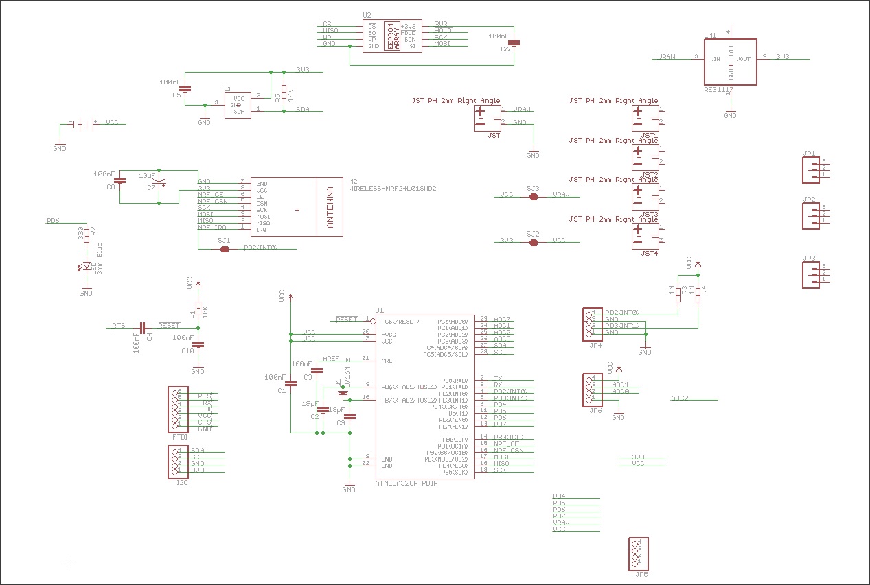
Here is the preview of where I am at now. This still needs to be routed, but for the moment I'm looking at placing components in the most efficient way (and trying to imagine how I would route wires around this node in tight spaces.
I'm also planning to include ATSHA204 and flash to make it a full MySensors compatible node (minus the MYSX connector, not sure what to do with that yet).
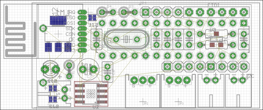
The working file schematic is still in "movement":+1:
-
@GertSanders you decided to keep JST I see. A few more jumpers here :)
Also do you assume soldering ntf24l01+ directly onto the board or via pins? -
@GertSanders Have you been thinking about powering it with a different source?
I have come across 26650, which is a super rechargeable battery (5000mAh) and very compact. -
@GertSanders Have you been thinking about powering it with a different source?
I have come across 26650, which is a super rechargeable battery (5000mAh) and very compact.@alexsh1 said:
26650
Fully charged these batteries are 4.2V, which is too high for the radio. In terms of cost, they require a special Li-Ion battery loader. Cutout voltage is aroud 2.5V. Capacity wise they would allow a node to work 3 years. Personally I'm happy with something over 1 year at 10th of the cost.
Related to your other question on the mounting of the NRF: if a battery is needed, I would need 1.27mm header to solder the radio in place, as one battery terminal sits below the NRF module. Without a battery holder mounted under the board, this is not needed. Personally I'm still looking for a positioning of the NRF module on the PCB directly and which allows the mounting of the batteryholder under the PCB. The NRF as it is positioned in the screenshot needs to move.
JST connectors seems a good choice in terms of cost, size and avoids wrong connections due to the tab in the connector (but you can still make mistakes on the wired end of course). -
@alexsh1 said:
26650
Fully charged these batteries are 4.2V, which is too high for the radio. In terms of cost, they require a special Li-Ion battery loader. Cutout voltage is aroud 2.5V. Capacity wise they would allow a node to work 3 years. Personally I'm happy with something over 1 year at 10th of the cost.
Related to your other question on the mounting of the NRF: if a battery is needed, I would need 1.27mm header to solder the radio in place, as one battery terminal sits below the NRF module. Without a battery holder mounted under the board, this is not needed. Personally I'm still looking for a positioning of the NRF module on the PCB directly and which allows the mounting of the batteryholder under the PCB. The NRF as it is positioned in the screenshot needs to move.
JST connectors seems a good choice in terms of cost, size and avoids wrong connections due to the tab in the connector (but you can still make mistakes on the wired end of course).@GertSanders said:
@alexsh1 said:
26650
Fully charged these batteries are 4.2V, which is too high for the radio. In terms of cost, they require a special Li-Ion battery loader. Cutout voltage is aroud 2.5V. Capacity wise they would allow a node to work 3 years. Personally I'm happy with something over 1 year at 10th of the cost.
Well, not exactly. Have a look here: http://forum.mysensors.org/topic/3309/powering-nodes-3-3v-with-18650-26650/7
The cost of LDO is about Eur 1 for 20 pieces including shipping from HK :)
No charger is needed (and I have one away) -> TP4056 with Battery protection is the answer. Just plug it into the USB to charge. The cost is Eur 2-3. The only cost here is battery itself. With PCB it is around Eur 10 vs 2xAA (or 2xAAA), which is what? Eur 4-5? Fine, but this is rechargeable and you can use it in other projects. -
@GertSanders : nice board and concept :) in my latest mytinycamel (I re-routed it recently) I have mysxconnector and 3xi2c , 24x49 but 0603 smd...and on this one radio module is on bottom...(I would like it on top but mytinycamel is a little bit room eater..but it's a cool power sequence so for fun!) I will try to upload it (and other stuff) maybe this week-end. I have routed something for lora too...32bits ;), still smd..
@alexsh1 : I think it's a matter of taste :) for instance, mytinycamel (my board) is not so expensive, and I can use only one 1.5v AA or AAA and last for years! put two in //, or don't ask me with a cheap lr14 type C 8000mah I have not tested yet lol! primary batt (aa/aaa/C) are cheap, in lithium version very low self discharge..not rechargeable but you have very often an aa/aaa batt somewhere ;) dilemma everywhere! -
@GertSanders : nice board and concept :) in my latest mytinycamel (I re-routed it recently) I have mysxconnector and 3xi2c , 24x49 but 0603 smd...and on this one radio module is on bottom...(I would like it on top but mytinycamel is a little bit room eater..but it's a cool power sequence so for fun!) I will try to upload it (and other stuff) maybe this week-end. I have routed something for lora too...32bits ;), still smd..
@alexsh1 : I think it's a matter of taste :) for instance, mytinycamel (my board) is not so expensive, and I can use only one 1.5v AA or AAA and last for years! put two in //, or don't ask me with a cheap lr14 type C 8000mah I have not tested yet lol! primary batt (aa/aaa/C) are cheap, in lithium version very low self discharge..not rechargeable but you have very often an aa/aaa batt somewhere ;) dilemma everywhere!@scalz LR14 Type C is a huge battery. 26650 is not. Though I agree it is a matter of taste/view. I have been using 18650/26650 to power up some projects and they performed well and universal - can be recharged and used for a power hungry projects and in my torch.
-
@scalz You are right re size - perhaps I was comparing it with type D. However, in terms of capacity, would you get a proper 5,000 mAh (not Trustfire capacity lol) out of lr14? We are not comparing apples with apples here as 26650 is 3.7V (and not 1.5V)
For super power demanding projects I use this one:
http://www.gearbest.com/rc-model-accessories/pp_143333.html?currency=GBP&gclid=CNupk7T0pMsCFcO4GwodKFAO6g -
@alexsh1 : cool :) not comparable, I know, lol..I just wanted to share other alternatives (26650 sized) as lr14 are very cheap in pack and can last very long time (with a booster 0.7v-1.5 to 3V) and you always have 3v during the whole life, can use every drop of power. but booster is not the best efficient for big hungry application. other 9v batt are nice too ;) and lipo can vent or good quality are expensive (good quality = true mAh, secure and low selfdischarge. but as you said it's rechargeable). And I am designing a lipo node too so.. :)
sorry for ot .. -
@scalz I suggest we move this discussion to http://forum.mysensors.org/topic/3309/powering-nodes-3-3v-with-18650-26650/2
6 x 1.5V LR14 on Amazon are £7 meantime 26650 3.7V 5000mAh is £9. Obviously one needs 2 for a project so its it £2.2 vs £9, but I am looking at it from a different angle. 26650 is a universal buy for me as well as an investment - I can power a project with, say, a motor or solenoid or connect a solar panel to charge the battery.
This is just my 2 cents -
This post is deleted!
-
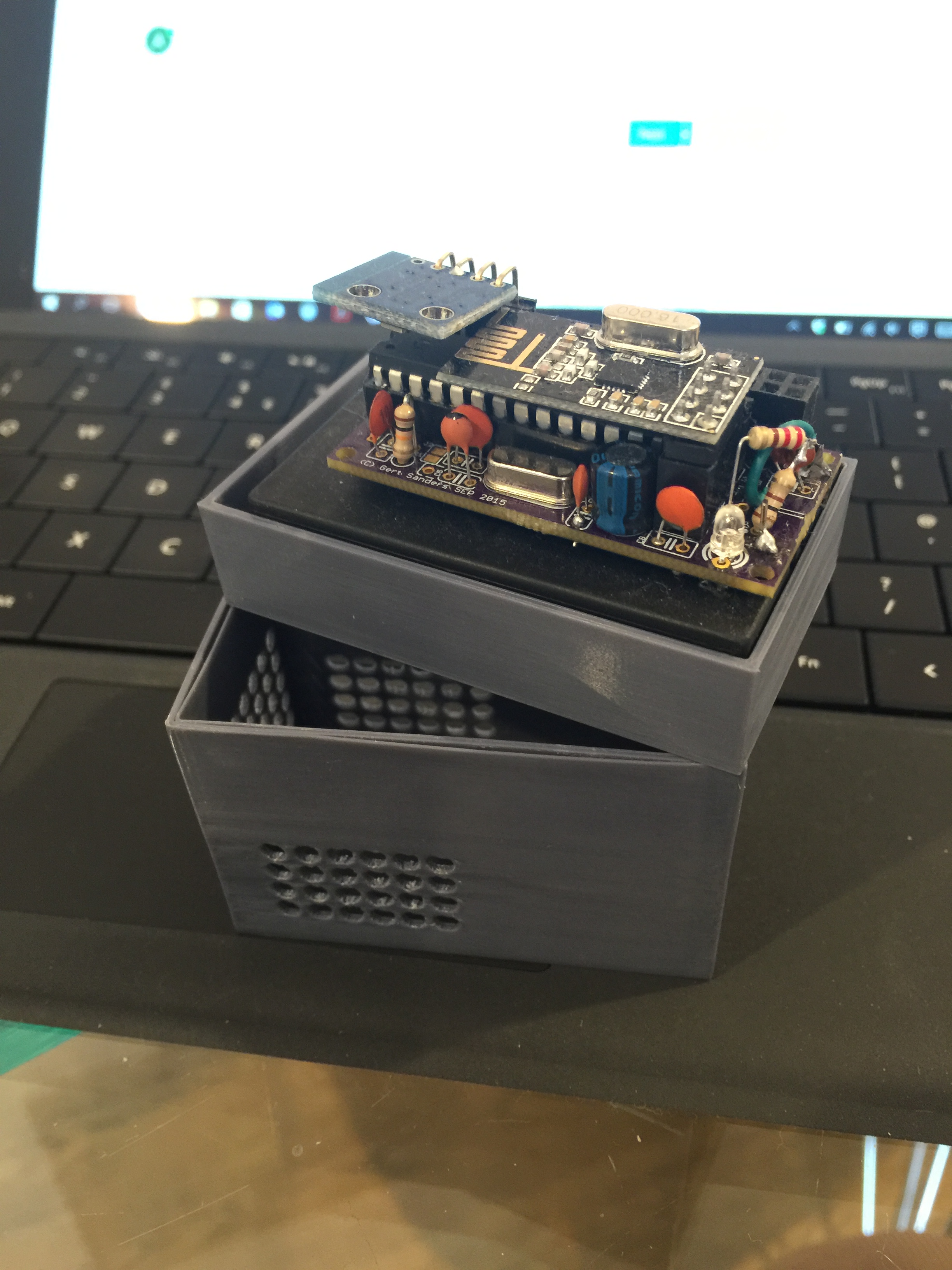
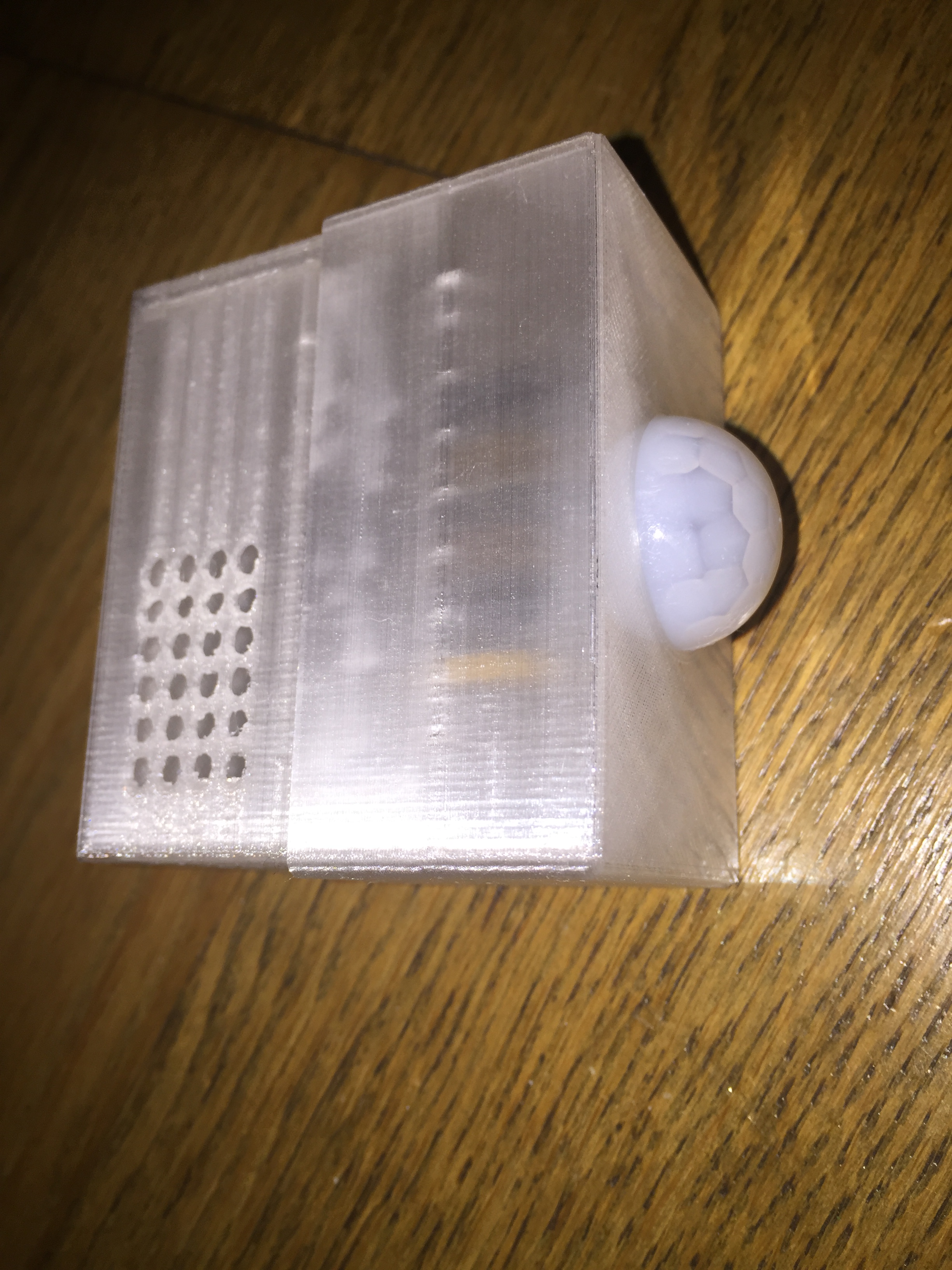
@GertSanders I really like this board - you are getting better and better! :)
You have now EEPROM? And the LED now on D5? You really like changing LED pin. :)Somebody was asking for PIR on the slim node.
Well, another teaser from me using previous version of your board (AA battery compartment and I am altering STL file to have it also for AAA battery case).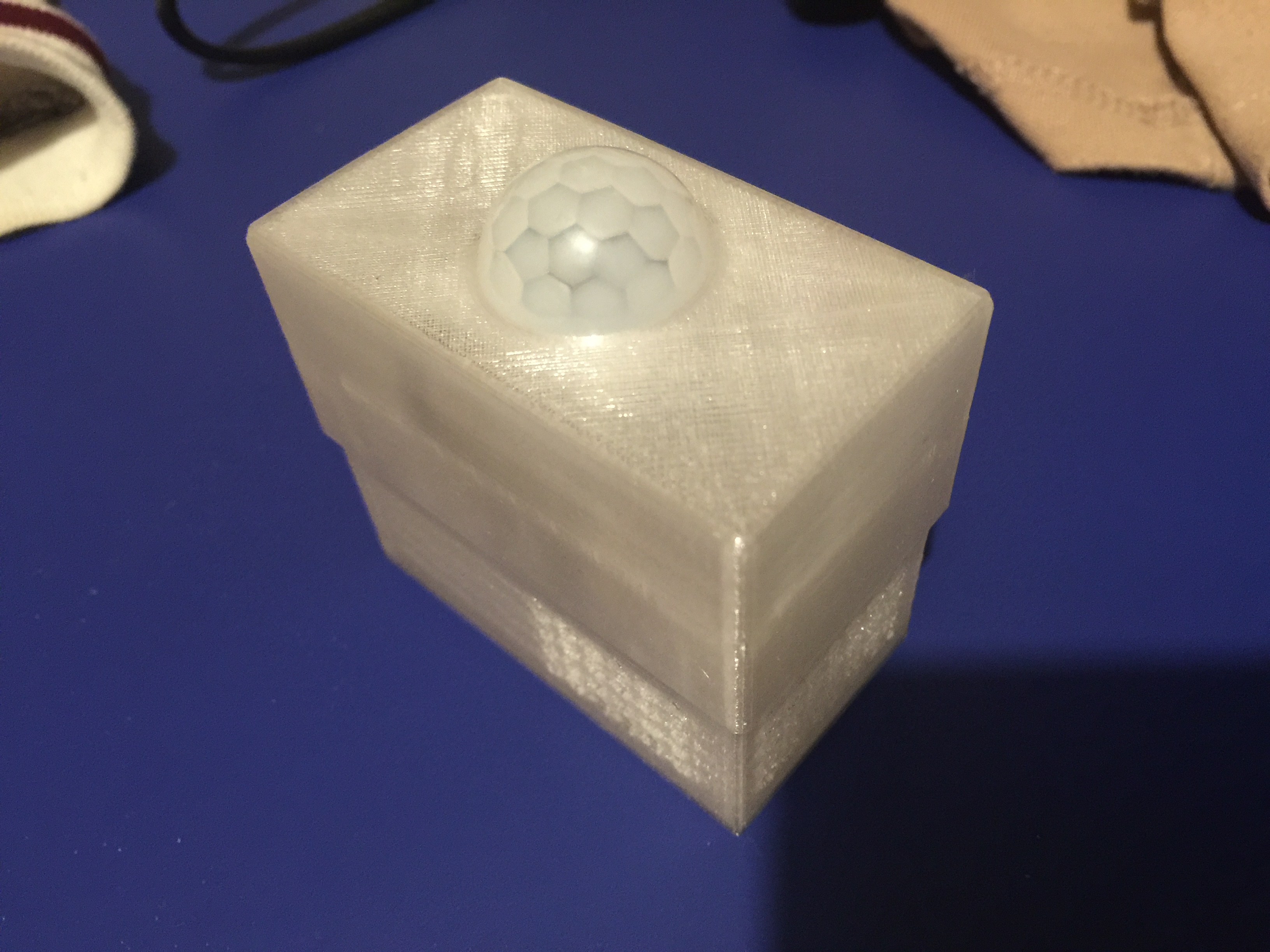
-
@GertSanders What are you planning to use for SJ4 and SJ5? Soldering or switches? I was thinking about the following: