livolo Glass Panel Touch Light Wall Switch + arduino 433Mhz
-
@Markhill it cannot work, this board needs external power because the ESP8266 he is using is too power hungry, the switch cannot provide enough power. And this board is sized for EU switch it will not work with US or US/AU switch.
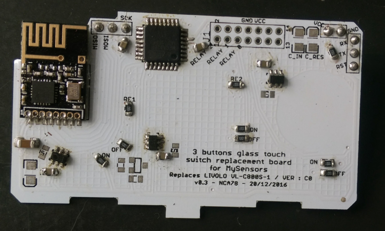
I'm working on 3 buttons and 4 buttons version with atmega and nrf24, power from the swith is enough so it's just a plug&play replacement. I'm testing the 3 buttons switch at the moment (same layout than 1 button in which only the center button is connected). It will be cheaper than 15$ if you solder it yourself, if you don't want to do smd soldering we can probably find a solution for pre-assembled boards.
-
@alexus said in livolo Glass Panel Touch Light Wall Switch + arduino 433Mhz:
hello. Is there a connection example with ESP?
Somewhere on youtube it seems, but using external power supply. It doesn't sound like a good idea to try to draw over 100mA from a power supply that was designed to provide less than 10, especially when a MySensors board can provide exactly the same functionality as a plug-in replacement of the livolo sensor board.
-
My goal would be to connect an arduino to the data pin on the power board and use the library to control livolo direct without a radio. The problem I have is that when i connect ground to ground on an ftdi I get magic smoke all over. Inuse my. Volt meter and sure enough the gnd pin is connected directly to the live input. Im guessing gnd and +3v "float" around the AC in some fashion.
Has anyone sucessfully bypassed the radio? Im thinking t may work if i power the arduino off the livolo power supply, or from a battery, but then if i connect that to an rs485 or other device with a real ground, kapow! At least that is what i am thinking will happen.
On a side note I have a regular, 2way, and remote switch, all the same revision and all US style, and from what I can tell the difference for 2way is a diode (d2) and a resettable fuse (r10). It lookes like there is basically a primative modem that sends/recieves the same data as the radio. (The radio is receive only, but 2 way has to be, well 2 ways). The "modem" is connected to "B" and "A" is connected to live and "gnd", which is why I think the dc voltage sort of floats on the ac.
In order to have isolation why not use an optocoupler from arduino to send logic high or low to the livolo relays board? This way they won't share the same gnd and no more issues of this kind in theory. But this means adding the optocoupler as an extra component..but I don't think this is a big issue and it should be cheap also.
-
@mtiutiu i usually need help with the obvious. Thank you.
What do you mean? You don't know how the wiring goes? I can provide a simple wiring diagram not a problem if that's needed.
-
I meant that using an optocoupler was an obvious solution, and I should have thought of it.
-
I managed to do some reverse engineering on the livolo dimmer switch. It seems that the touch MCU talks to the dimmer MCU via USART (idle: low, 19200 bps, 1 start, 1 stop, 8 data). Each 20 msec the dimmer MCU sends a byte that shows the level of the dimmer and the touch MCU replies with a byte that has bit 0 set to one if touch is present, rest of the bits are all 0 (except for each 10th reply, when all the other bits are 1).
Also the 433MHz radio signal is decoded by the touch MCU not by the dimmer MCU. -
I managed to do some reverse engineering on the livolo dimmer switch. It seems that the touch MCU talks to the dimmer MCU via USART (idle: low, 19200 bps, 1 start, 1 stop, 8 data). Each 20 msec the dimmer MCU sends a byte that shows the level of the dimmer and the touch MCU replies with a byte that has bit 0 set to one if touch is present, rest of the bits are all 0 (except for each 10th reply, when all the other bits are 1).
Also the 433MHz radio signal is decoded by the touch MCU not by the dimmer MCU.@Andrei-Călin-Tătar said in livolo Glass Panel Touch Light Wall Switch + arduino 433Mhz:
Also the 433MHz radio signal is decoded by the touch MCU not by the dimmer MCU.
The touch mcu does this for non dimming temote modules also. I think it uses mostly the same system for the 2way switches also.
-
I decided in the end to completely remove both MCUs and replace them with one mega328p, at42qt1010 and one nrf24l01. The problem is that it must be really power efficient. Once the light goes close to full power, the current drops significantly. I also noticed on the PCB space for a battery and a transistor that controls when it's connected to the power supply. Do the switches that come with RF modules have the battery location (B1 I think) populated?
@Andrei-Călin-Tătar b1 is the buzzer. When you hold a touch pad down for more than 5 seconds, the switch goes into learning mode and the buzzer makes a sound.
-
@Andrei-Călin-Tătar b1 is the buzzer. When you hold a touch pad down for more than 5 seconds, the switch goes into learning mode and the buzzer makes a sound.
@wallyllama ah, that makes sense. thanks for the info!
-
OK, here is what I managed to get working so far. I didn't use mysensors in the end but the sketch can be adapted. I must admit it's not the cleanest code.
So, I removed both microcontrollers from the base and the touch panel. I added a AT42QT1010 for touch detection (10k resistor, 47nF cap) and also replaced the led resistors from the touch panel with 2.2k ones (the light was too dimm, now it's a bit too bright :D ).Rest of the mods should be easy to see from the images. I didn't roll my own PCBs since I needed to adapt only 6 switches.
Features in the sketch: manual dimmer mode (works the same as the normal switch, just with control and brightness report); manual on/off mode (switches on/off on the start of a touch; the brightness can be set - default 100); manual disabled; when changing the brightness it goes through a ramp, it doesn't go directly to max or min. The modes, brightness, etc. can be changed via RF.
Base mod: https://photos.app.goo.gl/ZGojnlm2ocBEaucp2
Touch panel mod: https://photos.app.goo.gl/UpG2UuMtK2qa6q4h1
And the sketch code: https://github.com/andrei-tatar/SensorsNetwork/blob/master/LightDimmer/LightDimmer.ino -
OK, here is what I managed to get working so far. I didn't use mysensors in the end but the sketch can be adapted. I must admit it's not the cleanest code.
So, I removed both microcontrollers from the base and the touch panel. I added a AT42QT1010 for touch detection (10k resistor, 47nF cap) and also replaced the led resistors from the touch panel with 2.2k ones (the light was too dimm, now it's a bit too bright :D ).Rest of the mods should be easy to see from the images. I didn't roll my own PCBs since I needed to adapt only 6 switches.
Features in the sketch: manual dimmer mode (works the same as the normal switch, just with control and brightness report); manual on/off mode (switches on/off on the start of a touch; the brightness can be set - default 100); manual disabled; when changing the brightness it goes through a ramp, it doesn't go directly to max or min. The modes, brightness, etc. can be changed via RF.
Base mod: https://photos.app.goo.gl/ZGojnlm2ocBEaucp2
Touch panel mod: https://photos.app.goo.gl/UpG2UuMtK2qa6q4h1
And the sketch code: https://github.com/andrei-tatar/SensorsNetwork/blob/master/LightDimmer/LightDimmer.ino@Andrei-Călin-Tătar - How did you solve the problem with the power? I tried powering arduino from the built-in 3V connection, but it only worked to turn the lights on. Once on, I almost couldn't communicate with the arduino anymore (like 1 attempt from 20 would be successful).
-
@Andrei-Călin-Tătar - How did you solve the problem with the power? I tried powering arduino from the built-in 3V connection, but it only worked to turn the lights on. Once on, I almost couldn't communicate with the arduino anymore (like 1 attempt from 20 would be successful).
@achurak1 - I limited the max brightness. At full brightness, the triac is off for 2.9ms (out of 10msec for 50Hz). That gives enough time to recharge the circuit for the arduino but it limits the power delivered to the light bulbs to about 80-90%. If I would go more than that I would get unstable results. The circuit isn't able to keep it's 3V at full brightness without an arduino connected.
-
@Andrei-Călin-Tătar - Understood, thanks! Why did you need a new touch sensor, could you reuse the existing one?
@achurak1 do you mean the AT42QT1010? seemed easier for me. I could've added touch detection in the sketch.
-
@achurak1 do you mean the AT42QT1010? seemed easier for me. I could've added touch detection in the sketch.
-
@Andrei-Călin-Tătar - can you please explain all of your jumper wires. US version looks differently obviously so it's really hard to figure out what you did there based on just the pictures.
@achurak1 I added some details over the photos:
https://photos.app.goo.gl/S7VxIrn58z99HRMp2 -
@DJONvl said in livolo Glass Panel Touch Light Wall Switch + arduino 433Mhz:
сегодня доделал Livolo+esp8266 пришлось помучаться с программой и схемой питания но все заработало[0_1485259118390_livolo_esp.mp4](Uploading 100%)