Battery percentage - Help needed
-
Hi guys.
So, I have to admit that I'm a total noob. But I hope some of you guys can spare me a minute.
I'm working on a small battery powered temp+hum sensor based on a Pro Mini, NRF24L01+ and a Si7021 sensor.
I would like to run it on a solar panel, and use a Li-Ion battery as storage for those rainy days (and nights off course).I have used m26872's the sketch from here, which seems to work fine:
http://forum.mysensors.org/topic/2067/my-slim-2aa-battery-node/115I am, however, at a loss when it comes to monitoring the battery charge (I realize that voltage/charge is not linear, but at least it gives a bit of an idea where things are going).
Can someone point me in the direction I need to go - both with hardware and sketch to monitor the Li-Ion charge and report it to the controller (I'm thinking about using Domoticz)?
At the moment the setup looks like this:
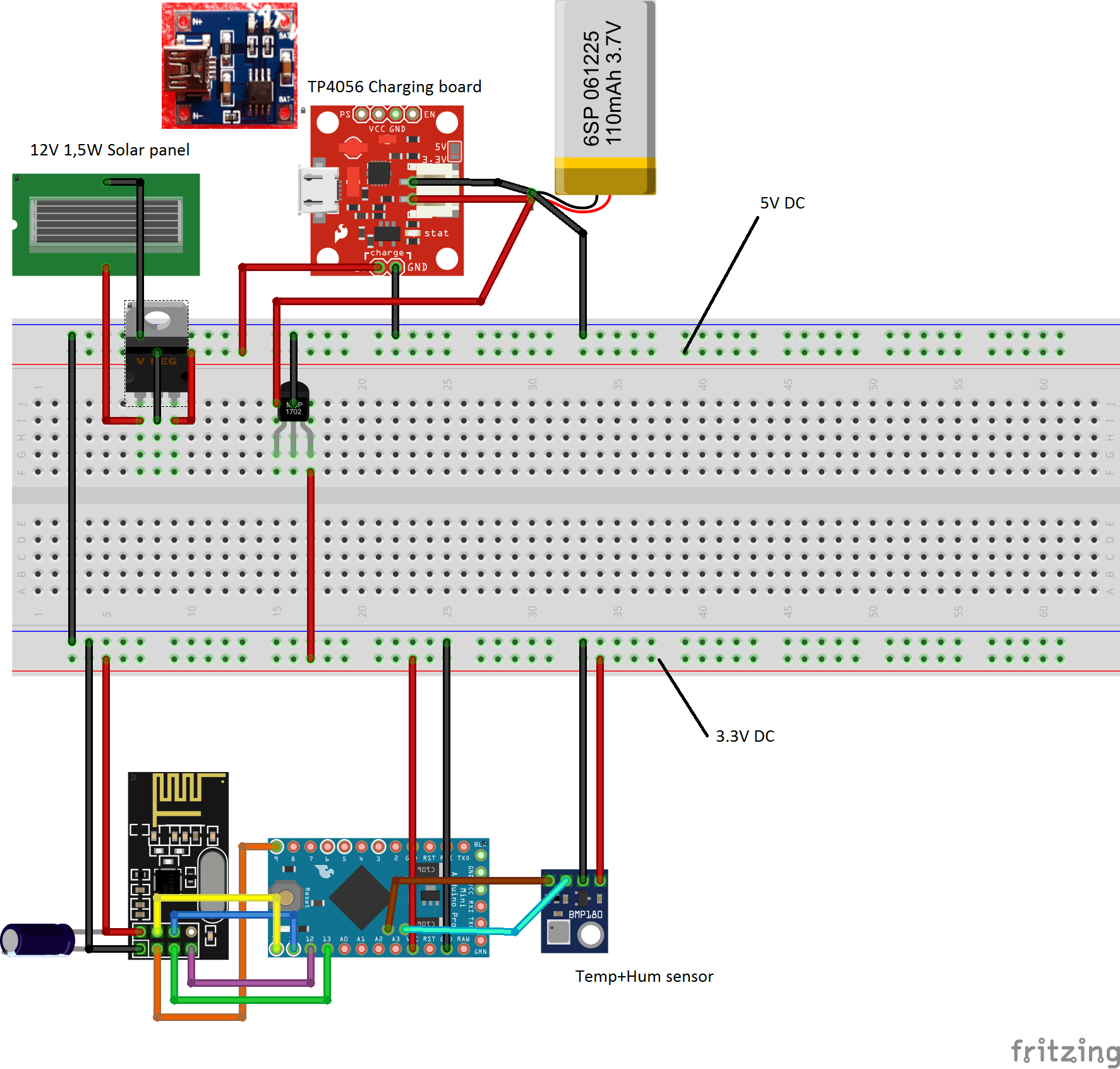
The current from the solar panel is regulated to 5V for the charging board.
The battery will operate between 4.2V and 3.2V, and the current on the battery side is regulated to 3.3V for the Arduino, radio and sensor.I guess I will have to add a couple of resistors and modify the sketch, but I don't know were to start!
-
Update:
So I've digged a bit more into voltage division and off course it's pretty simple (ohms law and everything).
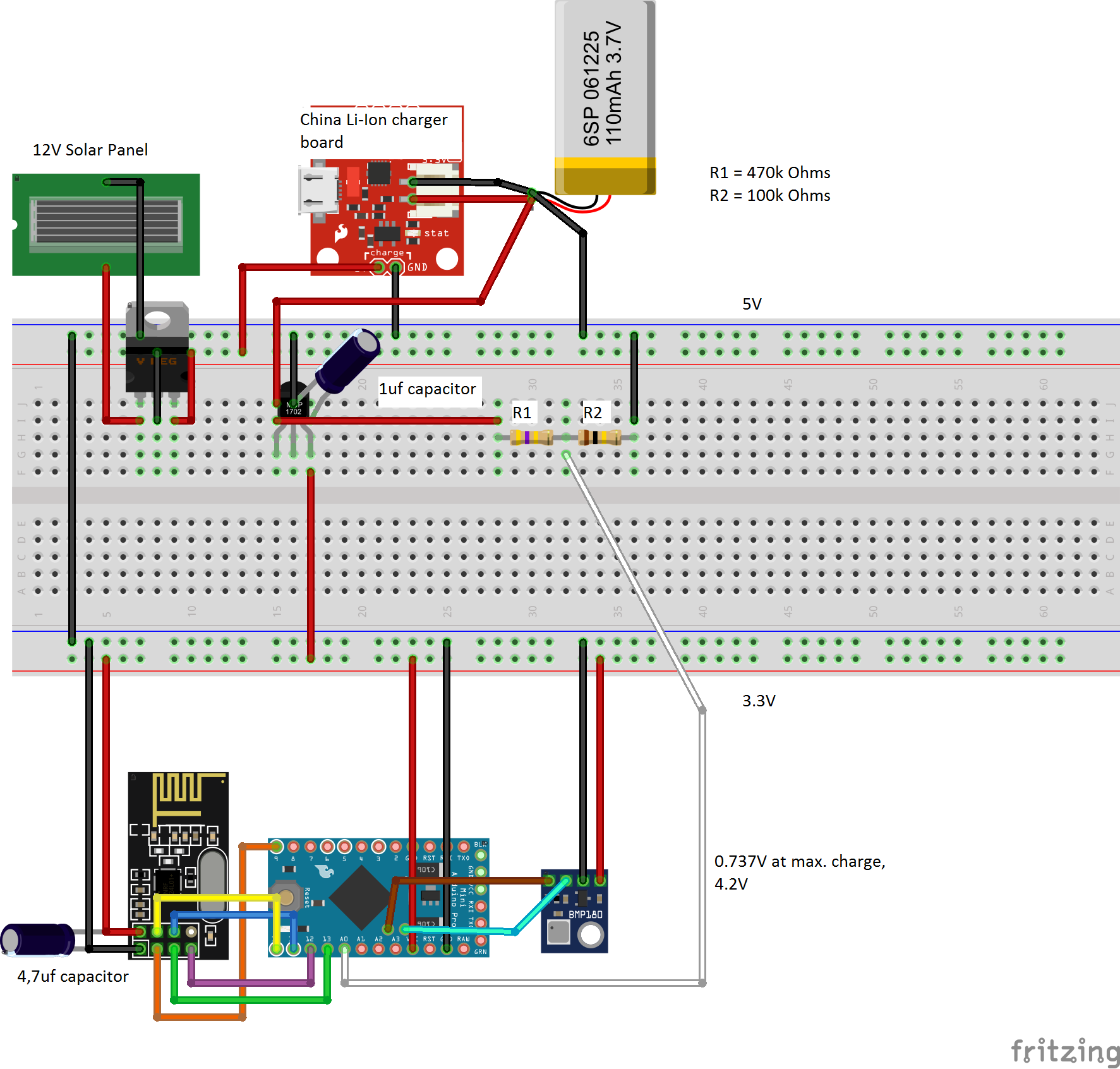
I've added a voltage divider, using a 470k and 100k resistor, and connected it to A0.The controller now shows the battery percentage - but quite obviously the sketch needs altering since the battery is almost fully charged, but but the controller only shows it at 12%.
The setup looks like this:
And the sketch like this:
/* Sketch with Si7021 and battery monitoring.
by m26872, 20151109
*/
#include <MySensor.h>
#include <Wire.h>
#include <SI7021.h>
#include <SPI.h>
#include <RunningAverage.h>

//#define DEBUG

#ifdef DEBUG
#define DEBUG_SERIAL(x) Serial.begin(x)
#define DEBUG_PRINT(x) Serial.print(x)
#define DEBUG_PRINTLN(x) Serial.println(x)
#else
#define DEBUG_SERIAL(x)
#define DEBUG_PRINT(x)
#define DEBUG_PRINTLN(x)
#endif

#define NODE_ID 1             // <<<<<<<<<<<<<<<<<<<<<<<<<<<   Enter Node_ID
#define CHILD_ID_TEMP 0
#define CHILD_ID_HUM 1
// #define SLEEP_TIME 15000 // 15s for DEBUG
#define SLEEP_TIME 180000   // 3 min
#define FORCE_TRANSMIT_CYCLE 10  // 3min*20=1/hour, 3min*10=1/2/hour
#define BATTERY_REPORT_CYCLE 20   // Once per 3min   =>   20*3 = 60 (one report/hour)
#define VMIN 3200
#define VMAX 4200
#define HUMI_TRANSMIT_THRESHOLD 0.5  // THRESHOLD tells how much the value should have changed since last time it was transmitted.
#define TEMP_TRANSMIT_THRESHOLD 0.5
#define AVERAGES 2

int batteryReportCounter = BATTERY_REPORT_CYCLE - 1;  // to make it report the first time.
int measureCount = 0;
float lastTemperature = -100;
int lastHumidity = -100;

RunningAverage raHum(AVERAGES);
SI7021 humiditySensor;

MySensor gw;
MyMessage msgTemp(CHILD_ID_TEMP,V_TEMP); // Initialize temperature message
MyMessage msgHum(CHILD_ID_HUM,V_HUM);

void setup() {
  DEBUG_SERIAL(115200);    // <<<<<<<<<<<<<<<<<<<<<<<<<< Note BAUD_RATE in MySensors.h
  DEBUG_PRINTLN("Serial started");

  DEBUG_PRINT("Voltage: ");
  DEBUG_PRINT(readVcc());
  DEBUG_PRINTLN(" mV");
/*
  delay(500);
  DEBUG_PRINT("Internal temp: ");
  DEBUG_PRINT(GetInternalTemp()); // Probably not calibrated. Just to print something.
  DEBUG_PRINTLN(" *C");
*/
  delay(500); // Allow time for radio if power useed as reset
  gw.begin(NULL,NODE_ID);
  gw.sendSketchInfo("EgTmpHumBat5min", "1.0 151106");
  gw.present(CHILD_ID_TEMP, S_TEMP);   // Present sensor to controller
  gw.present(CHILD_ID_HUM, S_HUM);
  DEBUG_PRINT("Node and "); DEBUG_PRINTLN("2 children presented.");

  raHum.clear();

}

void loop() {

  measureCount ++;
  batteryReportCounter ++;
  bool forceTransmit = false;

  if (measureCount > FORCE_TRANSMIT_CYCLE) {
    forceTransmit = true;
  }
  sendTempHumidityMeasurements(forceTransmit);
/*
  // Read and print internal temp
  float temperature0 = static_cast<float>(static_cast<int>((GetInternalTemp()+0.5) * 10.)) / 10.;
  DEBUG_PRINT("Internal Temp: "); DEBUG_PRINT(temperature0); DEBUG_PRINTLN(" *C");
*/
  // Check battery
  if (batteryReportCounter >= BATTERY_REPORT_CYCLE) {
    long batteryVolt = readVcc();
    DEBUG_PRINT("Battery voltage: "); DEBUG_PRINT(batteryVolt); DEBUG_PRINTLN(" mV");
    uint8_t batteryPcnt = constrain(map(batteryVolt,VMIN,VMAX,0,100),0,255);
    DEBUG_PRINT("Battery percent: "); DEBUG_PRINT(batteryPcnt); DEBUG_PRINTLN(" %");
    gw.sendBatteryLevel(batteryPcnt);
    batteryReportCounter = 0;
  }

  gw.sleep(SLEEP_TIME);
}

// function for reading Vcc by reading 1.1V reference against AVcc. Based from http://provideyourown.com/2012/secret-arduino-voltmeter-measure-battery-voltage/
// To calibrate reading replace 1125300L with scale_constant = internal1.1Ref * 1023 * 1000, where internal1.1Ref = 1.1 * Vcc1 (per voltmeter) / Vcc2 (per readVcc() function)
long readVcc() {
  // set the reference to Vcc and the measurement to the internal 1.1V reference
  ADMUX = _BV(REFS0) | _BV(MUX3) | _BV(MUX2) | _BV(MUX1);
  delay(2); // Wait for Vref to settle
  ADCSRA |= _BV(ADSC); // Start conversion
  while (bit_is_set(ADCSRA,ADSC)); // measuring
  uint8_t low  = ADCL; // must read ADCL first - it then locks ADCH
  uint8_t high = ADCH; // unlocks both
  long result = (high<<8) | low;
  result = 1125300L / result; // Calculate Vcc (in mV); 1125300 = 1.1*1023*1000
  return result; // Vcc in millivolts
}
// function for reading internal temp. From http://playground.arduino.cc/Main/InternalTemperatureSensor
double GetInternalTemp(void) {  // (Both double and float are 4 byte in most arduino implementation)
  unsigned int wADC;
  double t;
  // The internal temperature has to be used with the internal reference of 1.1V. Channel 8 can not be selected with the analogRead function yet.
  ADMUX = (_BV(REFS1) | _BV(REFS0) | _BV(MUX3));   // Set the internal reference and mux.
  ADCSRA |= _BV(ADEN);  // enable the ADC
  delay(20);            // wait for voltages to become stable.
  ADCSRA |= _BV(ADSC);  // Start the ADC
  while (bit_is_set(ADCSRA,ADSC));   // Detect end-of-conversion
  wADC = ADCW;   // Reading register "ADCW" takes care of how to read ADCL and ADCH.
  t = (wADC - 88.0 ) / 1.0;   // The default offset is 324.31.
  return (t);   // The returned temperature in degrees Celcius.
}

/*********************************************
 * * Sends temperature and humidity from Si7021 sensor
 * Parameters
 * - force : Forces transmission of a value (even if it's the same as previous measurement)
 *********************************************/
void sendTempHumidityMeasurements(bool force) {
  bool tx = force;

  si7021_env data = humiditySensor.getHumidityAndTemperature();

  float temperature = data.celsiusHundredths / 100.0;
  DEBUG_PRINT("T: ");DEBUG_PRINTLN(temperature);
  float diffTemp = abs(lastTemperature - temperature);
  DEBUG_PRINT(F("TempDiff :"));DEBUG_PRINTLN(diffTemp);
  if (diffTemp > TEMP_TRANSMIT_THRESHOLD || tx) {
    gw.send(msgTemp.set(temperature,1));
    lastTemperature = temperature;
    measureCount = 0;
    DEBUG_PRINTLN("T sent!");
  }

  int humidity = data.humidityPercent;
  DEBUG_PRINT("H: ");DEBUG_PRINTLN(humidity);
  raHum.addValue(humidity);
  humidity = raHum.getAverage();  // MA sample imply reasonable fast sample frequency
  float diffHum = abs(lastHumidity - humidity);
  DEBUG_PRINT(F("HumDiff  :"));DEBUG_PRINTLN(diffHum);
  if (diffHum > HUMI_TRANSMIT_THRESHOLD || tx) {
    gw.send(msgHum.set(humidity));
    lastHumidity = humidity;
    measureCount = 0;
    DEBUG_PRINTLN("H sent!");
  }

}
Any hints would be welcome.
-
Your 100 k ohm should be 1 M Ohm
And you swapped the resistors, R1 should be 1Mohm, R2 should be 470kohm.
And to stabilize the readings a bit, add a 0.1uF capacitor over R2@ericvdb I replaced the resistors as suggested and added a capacitor (the smallest one I have a hand i 2.2uf - hope that's okay).
Now it shows 10% at full charge:Serial started Voltage: 3309 mV //bla bla bla T: 24.41 //more bla. H: 44 //transmit bla bla bla Battery voltage: 3300 mV Battery percent: 10 %Actual current on battery is 4.19V
-
@boozz
Sounds like a plan :dancers:But where do I do it?
Here, somewhere?if (batteryReportCounter >= BATTERY_REPORT_CYCLE) { long batteryVolt = readVcc(); DEBUG_PRINT("Battery voltage: "); DEBUG_PRINT(batteryVolt); DEBUG_PRINTLN(" mV"); uint8_t batteryPcnt = constrain(map(batteryVolt,VMIN,VMAX,0,100),0,255); DEBUG_PRINT("Battery percent: "); DEBUG_PRINT(batteryPcnt); DEBUG_PRINTLN(" %"); gw.sendBatteryLevel(batteryPcnt); batteryReportCounter = 0; } -
Update..
Tried it like this:// Check battery if (batteryReportCounter >= BATTERY_REPORT_CYCLE) { long batteryVolt = readVcc(); DEBUG_PRINT("Battery voltage: "); DEBUG_PRINT(batteryVolt); DEBUG_PRINTLN(" mV"); uint8_t batteryPcnt = constrain(map(batteryVolt,VMIN,VMAX,0,100),0,255)*10; DEBUG_PRINT("Battery percent: "); DEBUG_PRINT(batteryPcnt); DEBUG_PRINTLN(" %"); gw.sendBatteryLevel(batteryPcnt); batteryReportCounter = 0; }And got this result:
Battery voltage: 3300 mV
Battery percent: 100 %
So at least it seems to work :dancer:
Hoping voltage will drop like crazy through the night ;) -
I like to collect 4 readings (every 15min) in an array and the take the average reading and send every hour. This way you will avoid getting readings going up and down and smoothen out the curve a bit.
-
Your setup with 470k and 100k would make a quite good divider ratio for that Li battery range. Maybe increase both a little to limit leakage current.
BUT you can NOT use the readVcc() function here since battery isn't connected to Vcc. Instead you should replace it the normal code used with the voltage divider and analogRead() function. Can't guide you, but it should be like the standard example sketch for battery monitoring. This will give you more info. http://forum.mysensors.org/topic/2210/battery-sensor-measure-for-li-ion-cells
@m26872 Thank you for the pointer.
I used the sketch from the link, but still the readings are quite far off.I have tried checking the actual voltage at the division point. It reads 0.58V with a battery charge of 3.81V.
I my math doesn't fail me, it should be 0.69V...I then looked at the actual resistance of R1 and R2.
R1=1012e3
R2=220e3Of course this changes things, but not too drastically - now it should be 0.68V.
So I'm 15% wrong at my division point!Any suggestions?
I should add that the serial output vary a bit at first, but then settles in after 30 seconds or so. I guess that could be because the capacitor is a bit on the large size...
-
#include <SPI.h> #include <MySensor.h> #include <DHT.h> #define CHILD_ID_HUM 0 #define CHILD_ID_TEMP 1 #define HUMIDITY_SENSOR_DIGITAL_PIN 3 // define values for the battery measurement #define R1 1012e3 #define R2 220e3 #define VMIN 3.2 #define VMAX 4.2 #define ADC_PRECISION 1023 #define VREF 1.1 MySensor gw; DHT dht; unsigned long SLEEP_TIME = 5000; // Sleep time between reads (in milliseconds) float lastTemp; float lastHum; boolean metric = true; MyMessage msgHum(CHILD_ID_HUM, V_HUM); MyMessage msgTemp(CHILD_ID_TEMP, V_TEMP); int oldBatteryPcnt = 0; int BATTERY_SENSE_PIN = A0; void setup() { // use the 1.1 V internal reference analogReference(INTERNAL); gw.begin(); dht.setup(HUMIDITY_SENSOR_DIGITAL_PIN); // Send the Sketch Version Information to the Gateway gw.sendSketchInfo("Humidity", "1.0"); // Register all sensors to gw (they will be created as child devices) gw.present(CHILD_ID_HUM, S_HUM); gw.present(CHILD_ID_TEMP, S_TEMP); metric = gw.getConfig().isMetric; } void loop() { int batteryPcnt = getBatteryPercentage(); Serial.print("Battery percent: "); Serial.print(batteryPcnt); Serial.println(" %"); if (oldBatteryPcnt != batteryPcnt) { // Power up radio after sleep gw.sendBatteryLevel(batteryPcnt); oldBatteryPcnt = batteryPcnt; } // totally random test values gw.send(msgTemp.set(20, 1)); gw.send(msgHum.set(42, 1)); gw.sleep(SLEEP_TIME); //sleep a bit } int getBatteryPercentage() { // read analog pin value int inputValue = analogRead(BATTERY_SENSE_PIN); // calculate the max possible value and therefore the range and steps float voltageDividerFactor = (R1 + R2) / R2; float maxValue = voltageDividerFactor * VREF; float voltsPerBit = maxValue / ADC_PRECISION; float batteryVoltage = voltsPerBit * inputValue; float batteryPercentage = ((batteryVoltage-VMIN)/(VMAX-VMIN))*100; //int batteryPercentage = map(batteryVoltage, 0, maxValue, 0, 100); return batteryPercentage; } -
#include <SPI.h> #include <MySensor.h> #include <DHT.h> #define CHILD_ID_HUM 0 #define CHILD_ID_TEMP 1 #define HUMIDITY_SENSOR_DIGITAL_PIN 3 // define values for the battery measurement #define R1 1012e3 #define R2 220e3 #define VMIN 3.2 #define VMAX 4.2 #define ADC_PRECISION 1023 #define VREF 1.1 MySensor gw; DHT dht; unsigned long SLEEP_TIME = 5000; // Sleep time between reads (in milliseconds) float lastTemp; float lastHum; boolean metric = true; MyMessage msgHum(CHILD_ID_HUM, V_HUM); MyMessage msgTemp(CHILD_ID_TEMP, V_TEMP); int oldBatteryPcnt = 0; int BATTERY_SENSE_PIN = A0; void setup() { // use the 1.1 V internal reference analogReference(INTERNAL); gw.begin(); dht.setup(HUMIDITY_SENSOR_DIGITAL_PIN); // Send the Sketch Version Information to the Gateway gw.sendSketchInfo("Humidity", "1.0"); // Register all sensors to gw (they will be created as child devices) gw.present(CHILD_ID_HUM, S_HUM); gw.present(CHILD_ID_TEMP, S_TEMP); metric = gw.getConfig().isMetric; } void loop() { int batteryPcnt = getBatteryPercentage(); Serial.print("Battery percent: "); Serial.print(batteryPcnt); Serial.println(" %"); if (oldBatteryPcnt != batteryPcnt) { // Power up radio after sleep gw.sendBatteryLevel(batteryPcnt); oldBatteryPcnt = batteryPcnt; } // totally random test values gw.send(msgTemp.set(20, 1)); gw.send(msgHum.set(42, 1)); gw.sleep(SLEEP_TIME); //sleep a bit } int getBatteryPercentage() { // read analog pin value int inputValue = analogRead(BATTERY_SENSE_PIN); // calculate the max possible value and therefore the range and steps float voltageDividerFactor = (R1 + R2) / R2; float maxValue = voltageDividerFactor * VREF; float voltsPerBit = maxValue / ADC_PRECISION; float batteryVoltage = voltsPerBit * inputValue; float batteryPercentage = ((batteryVoltage-VMIN)/(VMAX-VMIN))*100; //int batteryPercentage = map(batteryVoltage, 0, maxValue, 0, 100); return batteryPercentage; }@ksga Can't see any error in your sketch. Sure you can add pinMode(BATTERY_SENSE_PIN, INPUT) but doubt it will matter.
So if you disconnect your divider from A0, the voltage at that divider point will raise to the right value?
-
@ksga Can't see any error in your sketch. Sure you can add pinMode(BATTERY_SENSE_PIN, INPUT) but doubt it will matter.
So if you disconnect your divider from A0, the voltage at that divider point will raise to the right value?
@m26872 I decided to trip everything from my breadboard and start over.
First thing - the voltage divider:
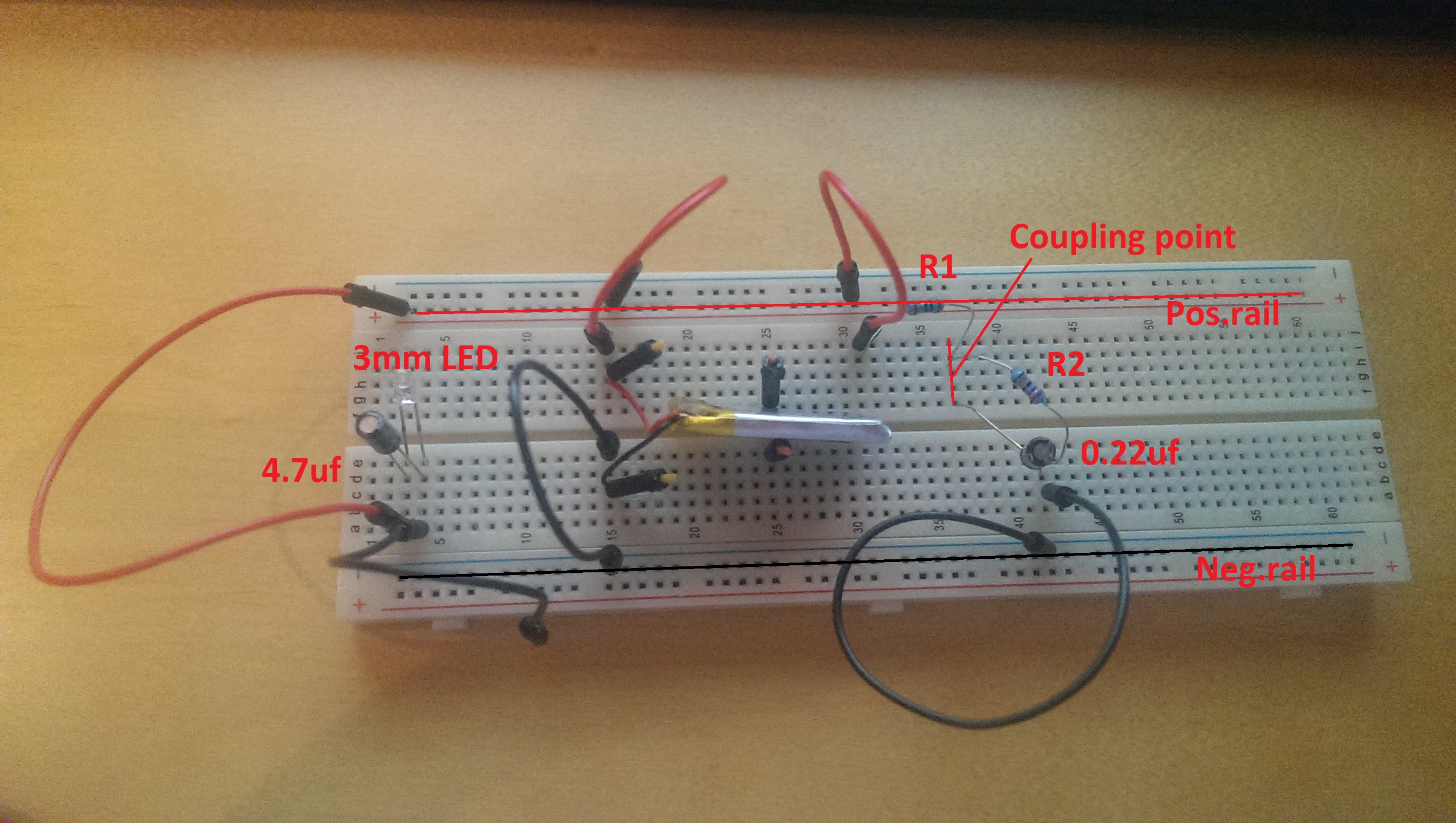
Simple Bat+ > pos.rail > R1 (1M, new specimen, verified resistance with multimeter) > R2(220k)/0.22uf capacitor > neg.rail > Bat-
In paralel I added an LED to put a bit of load on the battery for more realistic current.The results are:
Battery current: 4.03V
Neg.rail to coupling point R1-R2: 0.61V
Coupling point R1-R2 to Pos.rail: 2.78VDoes that make any sense?
I would expect 0.61V+2.78V=4.03V (or maybe I still haven't grasped the concept.)Hopefully this photo will make someone wiser than me point out my many mistakes ;-)
-
@m26872 I decided to trip everything from my breadboard and start over.
First thing - the voltage divider:
Simple Bat+ > pos.rail > R1 (1M, new specimen, verified resistance with multimeter) > R2(220k)/0.22uf capacitor > neg.rail > Bat-
In paralel I added an LED to put a bit of load on the battery for more realistic current.The results are:
Battery current: 4.03V
Neg.rail to coupling point R1-R2: 0.61V
Coupling point R1-R2 to Pos.rail: 2.78VDoes that make any sense?
I would expect 0.61V+2.78V=4.03V (or maybe I still haven't grasped the concept.)Hopefully this photo will make someone wiser than me point out my many mistakes ;-)
@ksga I can't see any current limiting resistor to the LED?
Start as simple as possible with few components. Short and few connections and wires to limit unexpected voltage drops in wires, breadboard or connections between. Remove the caps. -
@ksga I can't see any current limiting resistor to the LED?
Start as simple as possible with few components. Short and few connections and wires to limit unexpected voltage drops in wires, breadboard or connections between. Remove the caps.@m26872 Thank you for sticking with me.. I'm quite puzzled by this.
Removed all caps. Added a 1k resistor in front of the LED.
Checked resistance of wires - individually and mounted (all ~0.5 Ohm)Readings remain the same:
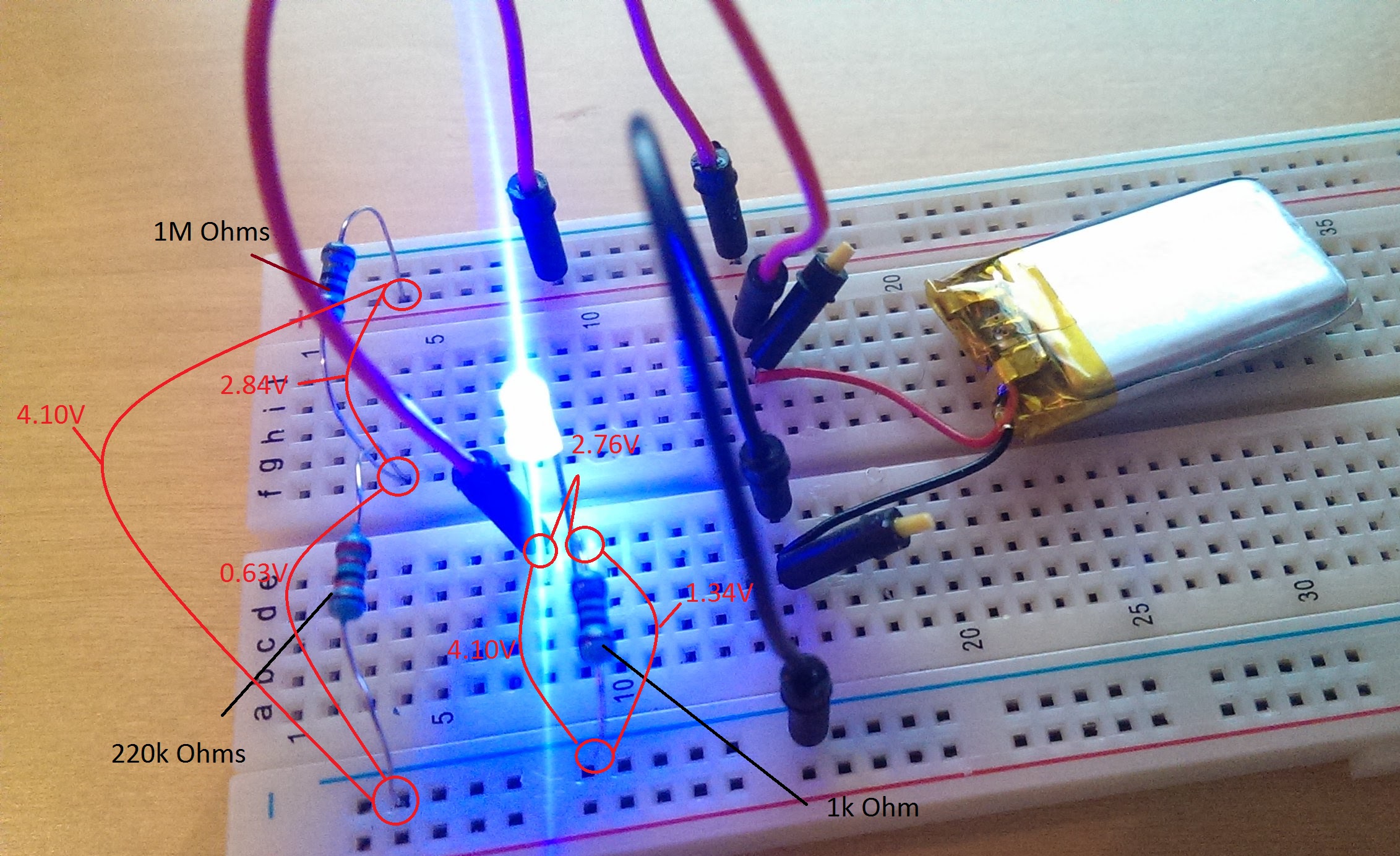
Where does the last "0,63V" go - and should the fact that it is the same as the current over R2 teach me something?
-
@m26872 Thank you for sticking with me.. I'm quite puzzled by this.
Removed all caps. Added a 1k resistor in front of the LED.
Checked resistance of wires - individually and mounted (all ~0.5 Ohm)Readings remain the same:
Where does the last "0,63V" go - and should the fact that it is the same as the current over R2 teach me something?
-
UPDATE:
So I decided to go ahead and connect the ProMini and nrf24l01+Now the output from the terminal fluctuated between 80% and 105% with no real pattern.
So I added a 0.22uf across R2Now the output is stable:
Battery percent: 104 %I still only measure 0.63V across R2.
I guess the remaining error could be written down to the 1.1V reference being off. I think I read somewhere that it can be 10% off! -
here is the battery related code from my battery powered temp sensor. Took a while to get the battery correct. Before this thread I had not seen any other code correcting for battery max / min voltages. I am using the 3.7V li-ion cells which actually seem to top out at 4.2V. I cap the percent at 99 for Vera.
float fmap(float x, float in_min, float in_max, float out_min, float out_max) {
  return (x - in_min) * (out_max - out_min) / (in_max - in_min) + out_min;
}

void loop()
{
  delay(dht.getMinimumSamplingPeriod());
  int sensorValue = analogRead(BATTERY_SENSE_PIN);

   // 1M, 330K divider across battery and using internal ADC ref of 1.1V
   // Sense point is bypassed with 0.1 uF cap to reduce noise at that point
   // ((1e6+330e3)/330e3)*1.1 = Vmax = 4.43 Volts
   // 4.43/1023 = Volts per bit = 0.0043336591723688
   // 4.2 = 100% 2.5 = 0%

   float batteryV  = sensorValue * 0.004333659;
   float batteryVmap = fabs(fmap(batteryV, 2.5, 4.2, 0.0, 1000.0));
   int batteryPcnt = batteryVmap / 10;
   if(batteryPcnt >= 100){
    batteryPcnt = 99;
Hello! It looks like you're interested in this conversation, but you don't have an account yet.
Getting fed up of having to scroll through the same posts each visit? When you register for an account, you'll always come back to exactly where you were before, and choose to be notified of new replies (either via email, or push notification). You'll also be able to save bookmarks and upvote posts to show your appreciation to other community members.
With your input, this post could be even better 💗
Register Login