💬 jModule
-
Are the boards uploaded to DirtyPCBs good and tested? I'd very much like to order a bunch of these but I am confused by the comments about missing pads. :? Can someone please confirm?
@zilog said:
Are the boards uploaded to DirtyPCBs good and tested? I'd very much like to order a bunch of these but I am confused by the comments about missing pads. :? Can someone please confirm?
What missing pads are your talking about ?
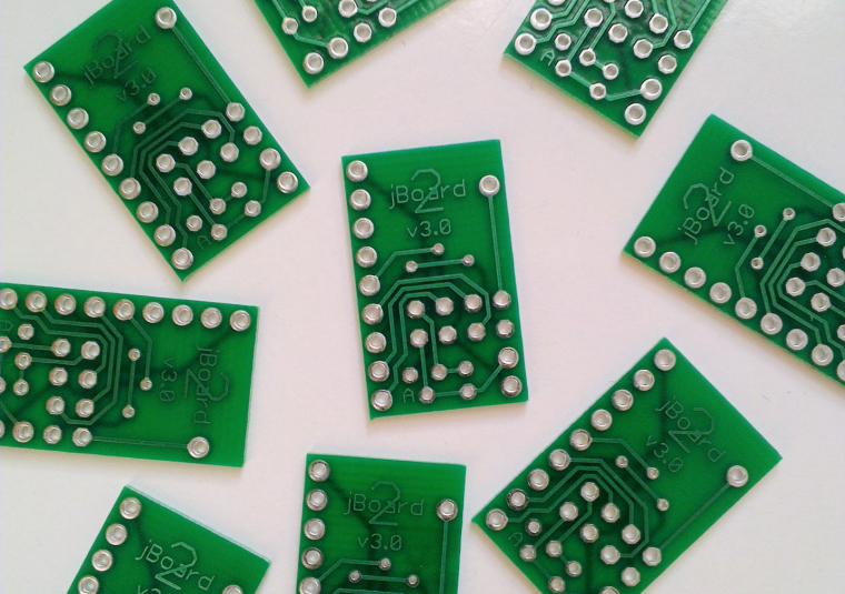
I used the panelized version modified by @ted to use XC6206 regulator and it's running fine (though without regulator at the moment as I have not received them yet, I use CR2032). And if you use a 0.6mm PCB thickness it's really easy to cut with regular cissors.
http://dirtypcbs.com/view.php?share=19651&accesskey=2e5e31a83bf6fe21510c3bc438e12df7 -
@alexsh1
The regulator on the board (AMS1117) consumes several mA at idle. You may need to find an alternative that has uA level quiescent current. I modified the board to use a XC6206 serial LDO (1uA standby current, see my previous post). I have the board manufactured by dirtypcb and have made sensors. Will test the battery life soon. -
How about a version with the SDA & SCL pins also routed to the header?
Sensors like the Si7021 are using the I2C interface@kted said:
How about a version with the SDA & SCL pins also routed to the header?
Sensors like the Si7021 are using the I2C interfaceI agree with you and I'm going to make a slightly different version of the board, to have both those pins available and to keep antenna away from the pro mini board.
-
@EddyG said:
Any news on the new board? I am really interested.
I'm testing a first version right now :)
It's running fine but there are some annoying defaults.
I'm making improvements to the PCB now and I will publish on openhardware.io in the coming weeks.I'm using SMD NRF 24 with antenna outside for better reception. Radio capacitor is SMD also but big size (1206) so easy to solder.
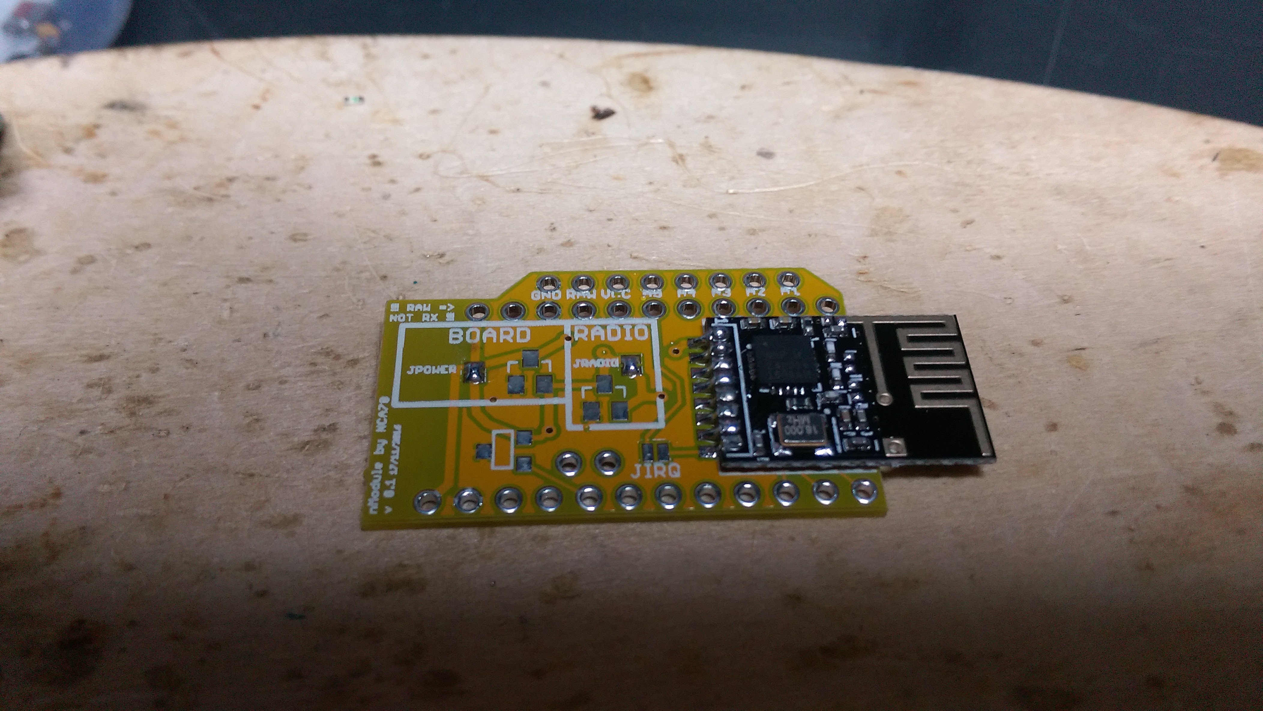
This is what the assembled board will look like, it takes a bit more surface than jModule but as you can see it's really flat, around 7mm and less than 6mm if you remove the big reset button on the pro mini.
-
Are these new boards compatible to the old footprint? I think the layout of the "high power"-rf24 versions did not change in the past coulpe of years and I can't rely on the "small"-boards .. got a solid home with conrete falls :D
@cimba007 the footprint is different.
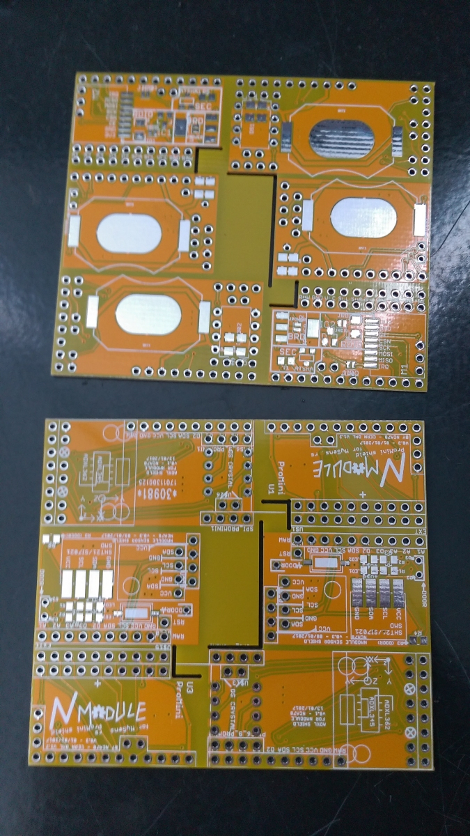
I think I have finished the new version now, I changed the regulator from RAW to VCC to put an AMS1117 so you will be able to use high power version of the NRF24 if you want. They exist in SMD version (so, with the same footprint than I use on this board) and they are of better quality than the cheap "through hole" versions, in addition to beeing much more compact with their ceramic antennas.
From my experience even the non pa/lna nrf24 has better radio performance than the cheap through hole version. With addition of not having any connectors/part of board below the antenna (like on the jModule) maybe it could be enough for some of your sensors at home.I have 30cm thick concrete walls in my appartments and no problem with the signal on the sensors using SMD version, while it was not so stable when using the through hole version. Probably my appartment is smaller than your home and I think the signal just "turns around" walls here, but you should give it a try ;)
-
I currently have 5 modules of the "old"-jboard and still 2-3 spare "high"-power modules left. I just recently noticed that most of my communication problems apparently came from RF24_PA_MAX settings. Currently running with RF24_PA_MIN I am very satisfied with the "high"-power modules. Was just inrested int he latest developement.
My recent focus switched over to make some nice housings for my nodes. Having a board+sensors is only half of the work ;-)
-
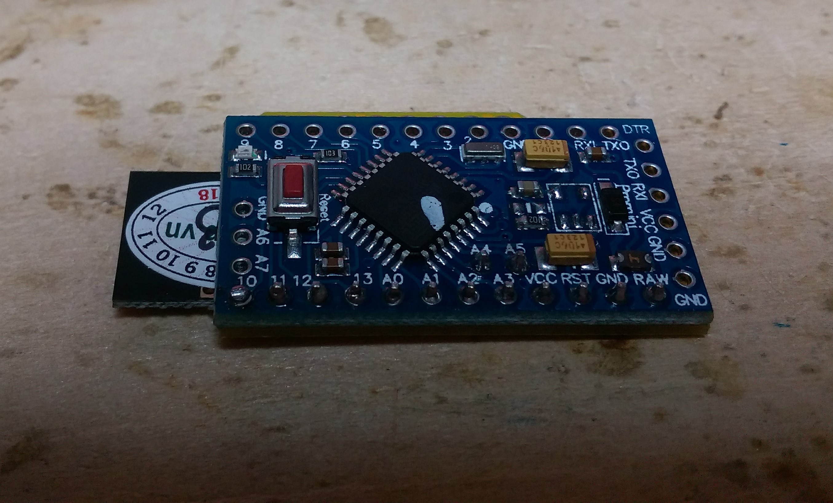
Yes I switched to SMD because the purpose of the board is to be very compact. With SMD everything is on one side and the board can be on the pro mini bottom without any gap.
But the board stays easy to solder too as I have put a 1206 SMD size. If you can solder the SMD nrf24 you can solder a 1206 capacitor. If you can't, keep using the jmodule, but really it's not very difficult :)I'll detail the board in another thread, I think I've hijacked this one enough :D
I'm making additional sensor boards in a hurry to send to dirty PCB and get them before lunar new year. When everything is sent I will upload to GitHub and post on openhardware.io. But it will need a few more weeks for me to receive and test the boards before before I advise you to order. -
Hey I have followed https://www.mysensors.org/build/battery and removed the onboard LED and 3.3 VDC regulator. I have powered using VCC pin. Do I need to external power the nrf module ?
-
Hey I have followed https://www.mysensors.org/build/battery and removed the onboard LED and 3.3 VDC regulator. I have powered using VCC pin. Do I need to external power the nrf module ?
@SubodhChettri Since you have removed the regulator, you should power the mini with 3.3V.
This is provided either by the jmodule's LDO which is capable to power the NRF, or directly by the battery (2xAA).
If you are using batteries, you dont need the LDO, so you bridge the Vin& Vout, and the 3.3V that feed the Mini go also to to the NRF. -
@Nca78 is it possible to buy them somewhere?
-
@Nca78 is it possible to buy them somewhere?
@Cliff-Karlsson said in 💬 jModule:
@Nca78 is it possible to buy them somewhere?
I'm not sure it's a good idea to share the dirtypcb link yet:
- they are not tested
- I don't even have all the scripts ready
- they need a bit of documentation to be usable
I will do my best to test them and share on openhardware.io next week.
Hello! It looks like you're interested in this conversation, but you don't have an account yet.
Getting fed up of having to scroll through the same posts each visit? When you register for an account, you'll always come back to exactly where you were before, and choose to be notified of new replies (either via email, or push notification). You'll also be able to save bookmarks and upvote posts to show your appreciation to other community members.
With your input, this post could be even better 💗
Register Login