💬 Various bootloader files based on Optiboot 6.2
-
Hello,
I will start some test on bootloader impact on battery so the timing is perfect !
One very useful thing to add in your project could be fuse settings and IDE board files ?David.
I can probably package this in a directory structure you could add to the Hardware folder in the Arduino files, but I do not have the time for it right now. I know that has been done for the original Optiboot 6.2 files already (including a pinout file for the various processor variants):
https://github.com/Optiboot/optibootFor the moment I have added my boards.txt file as I use it in my Arduino IDE (common), it shows some fuse settings, but you are right: a document describing the fuse settings to use, and their effect on a bootloader would be a nice reference for many people.
-
Hello,
I will try some bootloader so I will be able to give you some fuse settings I have tested to.
One more question, what B0 means ? I understood it's the pin for the LED ? Why B ? It's not D0 for digital 0 ?David.
@carlierd
"B0" is the Port B - pin 0 as is the terminology in AVR compiler ("port pins"). It is the parameter I need to add to GCC compiler to be able to use that pin.In Arduino IDE terms this is digital arduino pin nr 8. On the DIL version of the chip it is physical pin nr 14. The Arduino IDE makes abstraction of the port pins, by designating numbers to the pins of various ports. The relation between the two can be found in the file "pins_arduino.h", which is stored in a subdirectory "variants". This allows the IDE to use the same number of "pin" for different versions of boards and processors.
In this file you will find (for the "standard" Arduino Uno the following comments:
// ATMEL ATMEGA8 & 168 / ARDUINO
//
//                  +-\/-+
//            PC6  1|    |28  PC5 (AI 5)
//      (D 0) PD0  2|    |27  PC4 (AI 4)
//      (D 1) PD1  3|    |26  PC3 (AI 3)
//      (D 2) PD2  4|    |25  PC2 (AI 2)
// PWM+ (D 3) PD3  5|    |24  PC1 (AI 1)
//      (D 4) PD4  6|    |23  PC0 (AI 0)
//            VCC  7|    |22  GND
//            GND  8|    |21  AREF
//            PB6  9|    |20  AVCC
//            PB7 10|    |19  PB5 (D 13)
// PWM+ (D 5) PD5 11|    |18  PB4 (D 12)
// PWM+ (D 6) PD6 12|    |17  PB3 (D 11) PWM
//      (D 7) PD7 13|    |16  PB2 (D 10) PWM
//      (D 8) PB0 14|    |15  PB1 (D 9) PWM
//                  +----+
//
// (PWM+ indicates the additional PWM pins on the ATmega168.)
In the diagram below you see the relation between IDE, physical and ATMEL definition of the pins for the DIL variant.
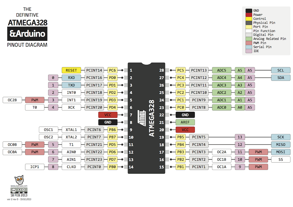
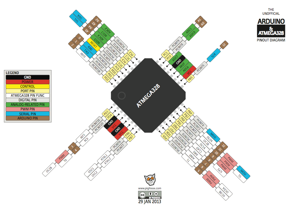
In this diagram below you see the CPU variant used on the Pro Mini. Port B, pin 0 is here physical pin 12, but for Arduino IDE this is still digital pin number 8:
-
@carlierd
"B0" is the Port B - pin 0 as is the terminology in AVR compiler ("port pins"). It is the parameter I need to add to GCC compiler to be able to use that pin.In Arduino IDE terms this is digital arduino pin nr 8. On the DIL version of the chip it is physical pin nr 14. The Arduino IDE makes abstraction of the port pins, by designating numbers to the pins of various ports. The relation between the two can be found in the file "pins_arduino.h", which is stored in a subdirectory "variants". This allows the IDE to use the same number of "pin" for different versions of boards and processors.
In this file you will find (for the "standard" Arduino Uno the following comments:
// ATMEL ATMEGA8 & 168 / ARDUINO
//
//                  +-\/-+
//            PC6  1|    |28  PC5 (AI 5)
//      (D 0) PD0  2|    |27  PC4 (AI 4)
//      (D 1) PD1  3|    |26  PC3 (AI 3)
//      (D 2) PD2  4|    |25  PC2 (AI 2)
// PWM+ (D 3) PD3  5|    |24  PC1 (AI 1)
//      (D 4) PD4  6|    |23  PC0 (AI 0)
//            VCC  7|    |22  GND
//            GND  8|    |21  AREF
//            PB6  9|    |20  AVCC
//            PB7 10|    |19  PB5 (D 13)
// PWM+ (D 5) PD5 11|    |18  PB4 (D 12)
// PWM+ (D 6) PD6 12|    |17  PB3 (D 11) PWM
//      (D 7) PD7 13|    |16  PB2 (D 10) PWM
//      (D 8) PB0 14|    |15  PB1 (D 9) PWM
//                  +----+
//
// (PWM+ indicates the additional PWM pins on the ATmega168.)
In the diagram below you see the relation between IDE, physical and ATMEL definition of the pins for the DIL variant.
In this diagram below you see the CPU variant used on the Pro Mini. Port B, pin 0 is here physical pin 12, but for Arduino IDE this is still digital pin number 8:
@GertSanders Perfect !!!
-
will there be an "Arduino Pro Mini" (Using external 8MHz scaled to 1MHz="X8M1") with LED B5 blink -> optiboot_atmega328_X8M1_057600_B5.hex avialable? preferable with BOD=disabled or set to 1,8v
Try this one.
0_1457034725597_optiboot_atmega328_X8M1_057600_B5.hex
I doubt uploading will work since 57600baud for a 1MHz device will generate around 8% error, which is way above the 2% AVRDUDE tolerates (I think). For the error calculation see below (WormFood's...)
But test it. I may be wrong.
I will make a 4800 baud version if you want later.
The BOD setting is something independent of the boot loader, you choose this with the fuses.
This boot loader expects to run at 1MHz, so you can either choose the internal 8MHz oscillator or a crystal at 8Mhz and set the fuses for clock division by 8. The clockdivision is also decided via the fuses and independent of the boot loader itself.There are only a few things that are important to a boot loader as far as I know:
Frequency of the cpu needs to be known at compile time, so that functions like wait() and delay() have an exact time reference (meaning that wait(1000) take 1 second and not some other duration).
Speed of the expected uploads also needs to be known, so that it can match the speed used to upload sketches. Not all combinations of cpu frequency and upload speed are possible. Some combinations have too much error. Google the "WormFood's AVR Baud Rate Calculator" and you will find info on this.
In the boards.txt file of the Arduino IDE you need to match the cpu and upload frequency.The fact that a LED needs to flash also needs to be known when compiling the boot loader (it's a parameter
This is how I started the make tool for Optiboot compilation for your bootloader:
make atmega328 BAUD_RATE=57600 AVR_FREQ=1000000L LED_START_FLASHES=3 LED=B5
Fuse settings:
For Clock division by 8
Internal 8Mhz oscillator
BOD at 1.8V:
Low: 0x62
High: 0xDF
Extended: 0xFE (or 06 in the boards.txt)For Clock division by 8
External Full Swing 8Mhz crystal
BOD at 1.8V:
Low: 0x77
High: 0xDF
Extended: 0xFE (or 06 in the boards.txt)For No BOD at all, Low and High fuses stay the same, only the Extended fuse changes:
Extended: 0xFF (or 07 in the boards.txt)Let me know if you can get it to work.
-
I tried to compile as you write that my baudrate was unrealistic high. to get a 4800 baudrate hexfile
I downloaded from github optiboot, and tried your compile settings, but get an AVR_FREQ error. I can understand that the AVR_FREQ isn't correctly taken as input from the commandline ans used by the makefile
I'm on Ubuntu Linux/media/bjacobse/documents/Downloads/optiboot-master/optiboot/bootloaders/optiboot$ make atmega328 BAUD_RATE=4800 AVR_FREQ=1000000L LED_FLASHES=3 LED=B5
avr-gcc (GCC) 4.8.2
Copyright (C) 2013 Free Software Foundation, Inc.
This is free software; see the source for copying conditions. There is NO
warranty; not even for MERCHANTABILITY or FITNESS FOR A PARTICULAR PURPOSE.avr-gcc: error: 000L: No such file or directory
make: [baudcheck] Error 1 (ignored)
baudcheck.tmp.sh: line 17: ( (H�00 + 4800 * 4) / ((4800 * 8))) - 1 : syntax error: invalid arithmetic operator (error token is "�00 + 4800 * 4) / ((4800 * 8))) - 1 ")
baudcheck.tmp.sh: line 25: (H�00/(8 * (()+1))) : syntax error: invalid arithmetic operator (error token is "�00/(8 * (()+1))) ")
BAUD RATE CHECK: Desired: 4800, Real: , UBRRL = , Error=-100.0%
avr-gcc -g -Wall -Os -fno-split-wide-types -mrelax -mmcu=atmega328p -DF_CPU=HW� 000L -DBAUD_RATE=4800 -DLED_START_FLASHES=3 -DLED=B5 -c -o optiboot.o optiboot.c
avr-gcc: error: 000L: No such file or directory
make: *** [optiboot.o] Error 1 -
I tried to compile as you write that my baudrate was unrealistic high. to get a 4800 baudrate hexfile
I downloaded from github optiboot, and tried your compile settings, but get an AVR_FREQ error. I can understand that the AVR_FREQ isn't correctly taken as input from the commandline ans used by the makefile
I'm on Ubuntu Linux/media/bjacobse/documents/Downloads/optiboot-master/optiboot/bootloaders/optiboot$ make atmega328 BAUD_RATE=4800 AVR_FREQ=1000000L LED_FLASHES=3 LED=B5
avr-gcc (GCC) 4.8.2
Copyright (C) 2013 Free Software Foundation, Inc.
This is free software; see the source for copying conditions. There is NO
warranty; not even for MERCHANTABILITY or FITNESS FOR A PARTICULAR PURPOSE.avr-gcc: error: 000L: No such file or directory
make: [baudcheck] Error 1 (ignored)
baudcheck.tmp.sh: line 17: ( (H�00 + 4800 * 4) / ((4800 * 8))) - 1 : syntax error: invalid arithmetic operator (error token is "�00 + 4800 * 4) / ((4800 * 8))) - 1 ")
baudcheck.tmp.sh: line 25: (H�00/(8 * (()+1))) : syntax error: invalid arithmetic operator (error token is "�00/(8 * (()+1))) ")
BAUD RATE CHECK: Desired: 4800, Real: , UBRRL = , Error=-100.0%
avr-gcc -g -Wall -Os -fno-split-wide-types -mrelax -mmcu=atmega328p -DF_CPU=HW� 000L -DBAUD_RATE=4800 -DLED_START_FLASHES=3 -DLED=B5 -c -o optiboot.o optiboot.c
avr-gcc: error: 000L: No such file or directory
make: *** [optiboot.o] Error 1You can not just compile on linux. The make file needs to be adapted to your setup. I compile my bootloaders on a Mac within a virtual machine running WinAVR version 2010 (oktober).
Tomorrow I will make a 4800 baud version. The 9600 baud 1Mhz should work as well, but the errorrate for uploads will be higher. Seems acceptable on some peoples boards.
-
I tried to compile as you write that my baudrate was unrealistic high. to get a 4800 baudrate hexfile
I downloaded from github optiboot, and tried your compile settings, but get an AVR_FREQ error. I can understand that the AVR_FREQ isn't correctly taken as input from the commandline ans used by the makefile
I'm on Ubuntu Linux/media/bjacobse/documents/Downloads/optiboot-master/optiboot/bootloaders/optiboot$ make atmega328 BAUD_RATE=4800 AVR_FREQ=1000000L LED_FLASHES=3 LED=B5
avr-gcc (GCC) 4.8.2
Copyright (C) 2013 Free Software Foundation, Inc.
This is free software; see the source for copying conditions. There is NO
warranty; not even for MERCHANTABILITY or FITNESS FOR A PARTICULAR PURPOSE.avr-gcc: error: 000L: No such file or directory
make: [baudcheck] Error 1 (ignored)
baudcheck.tmp.sh: line 17: ( (H�00 + 4800 * 4) / ((4800 * 8))) - 1 : syntax error: invalid arithmetic operator (error token is "�00 + 4800 * 4) / ((4800 * 8))) - 1 ")
baudcheck.tmp.sh: line 25: (H�00/(8 * (()+1))) : syntax error: invalid arithmetic operator (error token is "�00/(8 * (()+1))) ")
BAUD RATE CHECK: Desired: 4800, Real: , UBRRL = , Error=-100.0%
avr-gcc -g -Wall -Os -fno-split-wide-types -mrelax -mmcu=atmega328p -DF_CPU=HW� 000L -DBAUD_RATE=4800 -DLED_START_FLASHES=3 -DLED=B5 -c -o optiboot.o optiboot.c
avr-gcc: error: 000L: No such file or directory
make: *** [optiboot.o] Error 1 -
@GertSanders
Thank you for the file, however I have some troubles, I can flash via USBtiny but I am not able to upload sketch via Arduino IDE+ FTDI,
will you check my settings are correct?Here is my boards.txt file for the optiboot
##############################################################pro328opti.name=BJa BOD 1,8V Optiboot, Arduino Pro Mini (3.3V, 8 MHz) w/ ATmega328
pro328opti.upload.protocol=arduino
pro328opti.upload.maximum_size=30720
pro328opti.upload.speed=4800pro328opti.bootloader.low_fuses=0x77
pro328opti.bootloader.high_fuses=0xDF
pro328opti.bootloader.extended_fuses=0x06
pro328opti.bootloader.path=optiboot
pro328opti.bootloader.file=1457256062840-optiboot_atmega328_x8m1_004800_b5.hex
pro328opti.bootloader.unlock_bits=0x3F
pro328opti.bootloader.lock_bits=0x0F
pro328opti.build.mcu=atmega328p
pro328opti.build.f_cpu=8000000L
pro328opti.build.core=arduino
pro328opti.build.variant=standard -
@GertSanders
Thank you for the file, however I have some troubles, I can flash via USBtiny but I am not able to upload sketch via Arduino IDE+ FTDI,
will you check my settings are correct?Here is my boards.txt file for the optiboot
##############################################################pro328opti.name=BJa BOD 1,8V Optiboot, Arduino Pro Mini (3.3V, 8 MHz) w/ ATmega328
pro328opti.upload.protocol=arduino
pro328opti.upload.maximum_size=30720
pro328opti.upload.speed=4800pro328opti.bootloader.low_fuses=0x77
pro328opti.bootloader.high_fuses=0xDF
pro328opti.bootloader.extended_fuses=0x06
pro328opti.bootloader.path=optiboot
pro328opti.bootloader.file=1457256062840-optiboot_atmega328_x8m1_004800_b5.hex
pro328opti.bootloader.unlock_bits=0x3F
pro328opti.bootloader.lock_bits=0x0F
pro328opti.build.mcu=atmega328p
pro328opti.build.f_cpu=8000000L
pro328opti.build.core=arduino
pro328opti.build.variant=standardAs you use the clock divider, you should inform the Arduino IDE that the processor is running slower.
So you need to set this:
pro328opti.build.f_cpu=1000000L
-
Sounds like good idea :-) Thanks
now the board.tx file is updated: pro328opti.build.f_cpu=1000000L
restart Arduino, but still get upload errors
Error messages:
Binary sketch size: 1,102 bytes (of a 30,720 byte maximum)
avrdude: stk500_recv(): programmer is not responding
avrdude: stk500_getsync() attempt 1 of 10: not in sync: resp=0x00
I feel it's an unlucky Sunday... Can you provide more ideas what I can do? -
Sounds like good idea :-) Thanks
now the board.tx file is updated: pro328opti.build.f_cpu=1000000L
restart Arduino, but still get upload errors
Error messages:
Binary sketch size: 1,102 bytes (of a 30,720 byte maximum)
avrdude: stk500_recv(): programmer is not responding
avrdude: stk500_getsync() attempt 1 of 10: not in sync: resp=0x00
I feel it's an unlucky Sunday... Can you provide more ideas what I can do?Not sure, but an out of sync message is usually because of a mismatch in speed between what the IDE en avrdude expect, and what the cpu does.
So I would check the fuses of the cpu to be sure. I will try this boot loader on one of my nodes to see if the boot loader itself is the problem. -
@GertSanders I installed your compiled bootloaders - thanks for compiling them, but I cannot compile a Blink sketch using 1Mhz internal one
Board GertSanders:avr:atmega328pO5M16c doesn't define a 'build.board' preference. Auto-set to: AVR_ATMEGA328PO5M16C Board GertSanders:avr:atmega328pO5M8c doesn't define a 'build.board' preference. Auto-set to: AVR_ATMEGA328PO5M8C Board breadboard:avr:atmega328bb doesn't define a 'build.board' preference. Auto-set to: AVR_ATMEGA328BB WARNING: Category '' in library UIPEthernet is not valid. Setting to 'Uncategorized' Build options changed, rebuilding all In file included from sketch\Blink.ino.cpp:1:0: C:\Program Files (x86)\Arduino\hardware\arduino\avr\cores\arduino/Arduino.h:249:26: fatal error: pins_arduino.h: No such file or directory #include "pins_arduino.h" ^ compilation terminated. exit status 1 Error compiling.``` -
@GertSanders I installed your compiled bootloaders - thanks for compiling them, but I cannot compile a Blink sketch using 1Mhz internal one
Board GertSanders:avr:atmega328pO5M16c doesn't define a 'build.board' preference. Auto-set to: AVR_ATMEGA328PO5M16C Board GertSanders:avr:atmega328pO5M8c doesn't define a 'build.board' preference. Auto-set to: AVR_ATMEGA328PO5M8C Board breadboard:avr:atmega328bb doesn't define a 'build.board' preference. Auto-set to: AVR_ATMEGA328BB WARNING: Category '' in library UIPEthernet is not valid. Setting to 'Uncategorized' Build options changed, rebuilding all In file included from sketch\Blink.ino.cpp:1:0: C:\Program Files (x86)\Arduino\hardware\arduino\avr\cores\arduino/Arduino.h:249:26: fatal error: pins_arduino.h: No such file or directory #include "pins_arduino.h" ^ compilation terminated. exit status 1 Error compiling.```My boards.txt file is pointing to a location you are not using.
You have your library in a different place then I.
You should make sure that the directory in which you put the variant matches with what you have. I can not know which directory you put the Arduino IDE, so matching this is an exercise for you ;-)
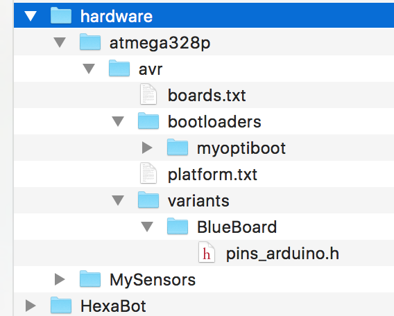
In my case, my variants boards is here:
\Dropbox\Arduino\hardware\atmega328p\avr\variants\BlueBoard\pins_arduino.h
This is matched with the fact that my boards file is here:
\Dropbox\Arduino\hardware\atmega328p\avr\boards.txt
Within the boards.txt file, I'm referring to the following variant: "BlueBoard". This is done here:
BlueBoard.build.core=arduino:arduino
BlueBoard.build.mcu=atmega328pBlueBoard.build.board=AVR_GERTSANDERSBLUEBOARD
BlueBoard.build.variant=BlueBoardYou seem to have a different path:
C:\Program Files (x86)\Arduino\hardware\arduino\avr\cores\arduino
I'm not sure where you added my files or boards.txt, but do not just copy it. You need to adapt your boards.txt file.
My "hardware" directory is within the Arduino sketch directory and contains this:
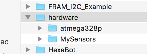
All my boot loaders are in directory "bootloaders\myoptiboot":
the file pins_arduino.h is a pins layout file for a standard atmega328p (copied from the "standard" variant directory.
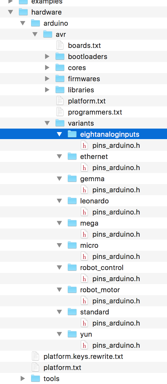
If you have a pro micro with the flat atmega328p, you need to use the "eightanaloginputs" variant.
This is what it looks like in my Arduino IDE installation directory:
-
My boards.txt file is pointing to a location you are not using.
You have your library in a different place then I.
You should make sure that the directory in which you put the variant matches with what you have. I can not know which directory you put the Arduino IDE, so matching this is an exercise for you ;-)
In my case, my variants boards is here:
\Dropbox\Arduino\hardware\atmega328p\avr\variants\BlueBoard\pins_arduino.h
This is matched with the fact that my boards file is here:
\Dropbox\Arduino\hardware\atmega328p\avr\boards.txt
Within the boards.txt file, I'm referring to the following variant: "BlueBoard". This is done here:
BlueBoard.build.core=arduino:arduino
BlueBoard.build.mcu=atmega328pBlueBoard.build.board=AVR_GERTSANDERSBLUEBOARD
BlueBoard.build.variant=BlueBoardYou seem to have a different path:
C:\Program Files (x86)\Arduino\hardware\arduino\avr\cores\arduino
I'm not sure where you added my files or boards.txt, but do not just copy it. You need to adapt your boards.txt file.
My "hardware" directory is within the Arduino sketch directory and contains this:
All my boot loaders are in directory "bootloaders\myoptiboot":
the file pins_arduino.h is a pins layout file for a standard atmega328p (copied from the "standard" variant directory.
If you have a pro micro with the flat atmega328p, you need to use the "eightanaloginputs" variant.
This is what it looks like in my Arduino IDE installation directory:
@GertSanders said:
I'm not sure where you added my files or boards.txt, but do not just copy it. You need to adapt your boards.txt file.
That's what I did - I adopted your boards.txt
All my bootloaders are in the hardware directory (C:\Users\Alex\Documents\Arduino\hardware). The hardware directory is located together with all my sketches in the Arduino directory. Now, for whatever reason, the error is point out to the completely different location:C:\Program Files (x86)\Arduino\hardware\arduino\avr\cores\arduino
C:\Program Files (x86)\Arduino\hardware\arduino\avr\cores\arduino
-
@GertSanders OK, I sorted it out.
I had to create "BlueBoard" and "standard" under "variants" and copy two corresponding files pins_arduino.h
At least I can compile now.Will try to upload a sketch later on and see if it works.
-
@GertSanders Unfortunately, I was able to upload the bootloader, but was not able to upload any sketches on the breadboard:
avrdude: stk500_getsync() attempt 1 of 10: not in sync: resp=0x78
avrdude: stk500_getsync() attempt 2 of 10: not in sync: resp=0xc0
avrdude: stk500_getsync() attempt 3 of 10: not in sync: resp=0x78
Not sure why - I can upload a sketch via the programmer though. Will upload Nick Gammon sketch to test the bootloader.
UPDATE1: Nick Gammon's sketch cannot detect the bootloader (tried 1MHz internal). Once again, I uploaded the bootloader (1Mhz internal) and the sketch via the programmer and it works, but....the serial monitor works only on 74880, despite for "1Mhz internal" boards.txt clearly says "9600":
BlueBoard.menu.mhz.1Mi= 1Mhz - internal - 9K6 upload speed
BlueBoard.menu.mhz.1Mi.bootloader.low_fuses=0xE2
BlueBoard.menu.mhz.1Mi.bootloader.high_fuses=0xDE
BlueBoard.menu.mhz.1Mi.build.f_cpu=1000000L
BlueBoard.menu.mhz.1Mi.upload.speed=9600
BlueBoard.menu.mhz.1Mi.bootloader.file=myoptiboot/optiboot_atmega328_01M_009600_B0.hex
Additionally, I loaded the ASCIITable example sketch and it states " Serial.begin(9600);"
I do not understand why it works only on 74880... -
@GertSanders Unfortunately, I was able to upload the bootloader, but was not able to upload any sketches on the breadboard:
avrdude: stk500_getsync() attempt 1 of 10: not in sync: resp=0x78
avrdude: stk500_getsync() attempt 2 of 10: not in sync: resp=0xc0
avrdude: stk500_getsync() attempt 3 of 10: not in sync: resp=0x78
Not sure why - I can upload a sketch via the programmer though. Will upload Nick Gammon sketch to test the bootloader.
UPDATE1: Nick Gammon's sketch cannot detect the bootloader (tried 1MHz internal). Once again, I uploaded the bootloader (1Mhz internal) and the sketch via the programmer and it works, but....the serial monitor works only on 74880, despite for "1Mhz internal" boards.txt clearly says "9600":
BlueBoard.menu.mhz.1Mi= 1Mhz - internal - 9K6 upload speed
BlueBoard.menu.mhz.1Mi.bootloader.low_fuses=0xE2
BlueBoard.menu.mhz.1Mi.bootloader.high_fuses=0xDE
BlueBoard.menu.mhz.1Mi.build.f_cpu=1000000L
BlueBoard.menu.mhz.1Mi.upload.speed=9600
BlueBoard.menu.mhz.1Mi.bootloader.file=myoptiboot/optiboot_atmega328_01M_009600_B0.hex
Additionally, I loaded the ASCIITable example sketch and it states " Serial.begin(9600);"
I do not understand why it works only on 74880...I will do some testing tonight, I have not used the 1MHz bootloader yet.
The instruction Serial.begin(9600) is independant of the upload.speed mentioned in the boards file. But I would expect that at 1MHz the higher serial comms speeds also give errors.
A possible reason for the problem, is that the fuse E2 actually means that you run the processor at 8Mhz internally, but without any clock division, while the bootloader was compiled for 1MHz. Without clock division by 8 the processor actually runs at 8Mhz (the speed of the internal oscillator), while all timing code is set for a cpu working frequency of 1Mhz. This would also explain why you can communicate at 74880 (which is close to 76800, which in turn is 8 times 9600).
I think the fuse should be set to both internal 8MHz oscillator AND clock division by 8. I do not know that correct value by hart, need to check that with a fuse calculator.
UPDATE: I think the lower fuse should be set to 0x62 instead of 0xE2.
-
OK, I have come to the following fuse settings for 1Mhz internal:
BlueBoard.menu.mhz.1Mi.bootloader.low_fuses=0x62
BlueBoard.menu.mhz.1Mi.bootloader.high_fuses=0xDE
For Optiboot, the high fuse is always 0xDE.
Now, a standard example sketch runs at 9600 - I have not checked if atmega328p is running at 1Mhz.Still have a problem uploading a sketch on the breadboard via FTDI