Skip to content
  • MySensors
  • OpenHardware.io
  • Categories
  • Recent
  • Tags
  • Popular
Skins
  • Light
  • Brite
  • Cerulean
  • Cosmo
  • Flatly
  • Journal
  • Litera
  • Lumen
  • Lux
  • Materia
  • Minty
  • Morph
  • Pulse
  • Sandstone
  • Simplex
  • Sketchy
  • Spacelab
  • United
  • Yeti
  • Zephyr
  • Dark
  • Cyborg
  • Darkly
  • Quartz
  • Slate
  • Solar
  • Superhero
  • Vapor

  • Default (No Skin)
  • No Skin
Collapse
Brand Logo
  1. Home
  2. Hardware
  3. Issues with setting up my Arduino Nano SerialGateway

Issues with setting up my Arduino Nano SerialGateway

Scheduled Pinned Locked Moved Hardware
17 Posts 4 Posters 5.4k Views 4 Watching
  • Oldest to Newest
  • Newest to Oldest
  • Most Votes
Reply
  • Reply as topic
Log in to reply
This topic has been deleted. Only users with topic management privileges can see it.
  • Christian SimonsenC Christian Simonsen

    Hi,

    I have a Arduino Nano (link) bought on eBay. And the NRF24L01 module also bought on ebay (link).

    The NRF module do not have any markings of the pins and the ebay product page do not contain any information either. I've therefore assumed that the pins are the same as on the tutorial page (link).

    I've uploaded the SerialGateway sketch to the Arduino Nano successfully without any changes. When looking at the Serial Monitor I get this message. "K��0;0;3;0;9;radio init fail" or "�RV��# �0;0;3;0;9;radio init fail" after trying to rewire it all from scratch.

    The Arduino Nano have the possibility to output 3.3 and 5 V, I've therefore used the Arduino Nano 3.3v pin rather than the recommended VCC pin (that I assume output 5V). Not sure if this is wrong...

    I'm using OSX 10.11.3 and Arduino 1.6.7. Though not sure if that is relevant.

    Do you have any tips as to what I'm doing wrong?

    TheoLT Offline
    TheoLT Offline
    TheoL
    Contest Winner
    wrote on last edited by
    #2

    @Christian-Simonsen Hard to tell. By the looks of the picture of your NFR24L01+ it's the same pinout as on the MySensors build page.

    There are a couple of checks that can be done:

    1. Always power the radio with 3.3V never 5V (which I assume is your VCC pin).
    2. Add a capacitor (4.7uF) as close to the radio as possible. (I always stick them, in the female pins of the Dupont cable).
    3. Double check the wiring. Make sure that MOSI and MISO aren't changed e.t.c.
    4. Select the correct board and processor in your Arduino IDE/

    Also set your serial monitor to 115200 baud, to might get rid of the strange symbols in your output. I have a couple of Nano based sensors which are running for more than half a year without any problem.

    1 Reply Last reply
    0
    • Christian SimonsenC Offline
      Christian SimonsenC Offline
      Christian Simonsen
      wrote on last edited by Christian Simonsen
      #3

      @TheoL

      Ref your suggestions.

      1. Always power the radio with 3.3V never 5V (which I assume is your VCC pin).
        So I guess my wiring is correct then if I understood you correctly. VCC is 5V and should not be used in my case.

      2. Add a capacitor (4.7uF) as close to the radio as possible. (I always stick them, in the female pins of the Dupont cable).
        - I already have a 4.7uF (50V) capacitor between GND and VCC on the NRF board, done the same way as you describe.

      3. Double check the wiring. Make sure that MOSI and MISO aren't changed e.t.c.
        - I've checked the NRF chip on the board and traced the connections to the PIN, and I can verify that the output pins are in the same way as the tutorial linked to above (Chip marking: NRF M 24L01+ 1452AB) - And double checked the wiring, can't find any errors

      4. Select the correct board and processor in your Arduino IDE/
        I uploaded the sketch again to the Arduino, and this removed the strange symbols in the Serial Monitor. Now I get "St0;0;3;0;9;radio init fail".

      I've also replaced the NRF module with another one ( I have 10). This didn't work either.

      Do I need to change anything in the sketch? eg. the input pins on the Arduino?

      By the way - I see no lights (LEDs) or signs that the NRF module receive any power. Not sure if there are any tiny LEDs on it... but it seems like it is..

      1 Reply Last reply
      0
      • Christian SimonsenC Offline
        Christian SimonsenC Offline
        Christian Simonsen
        wrote on last edited by
        #4

        In case it was something wrong with the Arduino Nano, I've replaced it and tried another. However Im still getting the same error. "0;0;3;0;9;radio init fail".

        Christian SimonsenC 1 Reply Last reply
        0
        • Christian SimonsenC Christian Simonsen

          In case it was something wrong with the Arduino Nano, I've replaced it and tried another. However Im still getting the same error. "0;0;3;0;9;radio init fail".

          Christian SimonsenC Offline
          Christian SimonsenC Offline
          Christian Simonsen
          wrote on last edited by
          #5

          @Christian-Simonsen

          I have now also tried the long-range version (link) and Im getting the same error. "0;0;3;0;9;radio init fail"

          Christian SimonsenC 1 Reply Last reply
          0
          • Christian SimonsenC Christian Simonsen

            @Christian-Simonsen

            I have now also tried the long-range version (link) and Im getting the same error. "0;0;3;0;9;radio init fail"

            Christian SimonsenC Offline
            Christian SimonsenC Offline
            Christian Simonsen
            wrote on last edited by
            #6

            @Christian-Simonsen

            I've also tried to switch the MISO and MOSI just in case I had got it wrong. No effect. Still the same error.. :( Running out of ideas...

            TheoLT 1 Reply Last reply
            0
            • Christian SimonsenC Christian Simonsen

              @Christian-Simonsen

              I've also tried to switch the MISO and MOSI just in case I had got it wrong. No effect. Still the same error.. :( Running out of ideas...

              TheoLT Offline
              TheoLT Offline
              TheoL
              Contest Winner
              wrote on last edited by
              #7

              @Christian-Simonsen what is the log saying when you monitor the gateway with serial monitor?

              also query this forum for St0;0;3;0;9;radio init fail. It might help you.

              1 Reply Last reply
              0
              • sundberg84S Offline
                sundberg84S Offline
                sundberg84
                Hardware Contributor
                wrote on last edited by
                #8

                @Christian-Simonsen most have been said above, but my thoughts:

                Radio init fail means

                1. Not wired correctly
                2. Not powered correctly
                3. Not a nrf24 with +

                Do you have a capacitor between grn/vcc on the 3.3v radio? This can make difference...

                Some reading regarding + and not + Nrf modules.
                http://forum.mysensors.org/topic/1153/we-are-mostly-using-fake-nrf24l01-s-but-worse-fakes-are-emerging/4
                http://forum.mysensors.org/topic/1664/which-are-the-best-nrf24l01-modules/2

                Controller: Proxmox VM - Home Assistant
                MySensors GW: Arduino Uno - W5100 Ethernet, Gw Shield Nrf24l01+ 2,4Ghz
                MySensors GW: Arduino Uno - Gw Shield RFM69, 433mhz
                RFLink GW - Arduino Mega + RFLink Shield, 433mhz

                Christian SimonsenC 1 Reply Last reply
                0
                • sundberg84S sundberg84

                  @Christian-Simonsen most have been said above, but my thoughts:

                  Radio init fail means

                  1. Not wired correctly
                  2. Not powered correctly
                  3. Not a nrf24 with +

                  Do you have a capacitor between grn/vcc on the 3.3v radio? This can make difference...

                  Some reading regarding + and not + Nrf modules.
                  http://forum.mysensors.org/topic/1153/we-are-mostly-using-fake-nrf24l01-s-but-worse-fakes-are-emerging/4
                  http://forum.mysensors.org/topic/1664/which-are-the-best-nrf24l01-modules/2

                  Christian SimonsenC Offline
                  Christian SimonsenC Offline
                  Christian Simonsen
                  wrote on last edited by
                  #9

                  @sundberg84

                  The chip marking is "NRF M 24L01+ 1452AB" - so I assume it is a + module.

                  I've tried to rewire it multiple times, I will try again.

                  1 Reply Last reply
                  0
                  • sundberg84S Offline
                    sundberg84S Offline
                    sundberg84
                    Hardware Contributor
                    wrote on last edited by sundberg84
                    #10

                    @Christian-Simonsen - Markings is not a guarantee...
                    See the threads i posted, there are alot if images.. maybe you can see something there. Or post a picture of your radios here... maybe we can spot something if you suspect its a fake.

                    Also - how do you power your node?

                    Controller: Proxmox VM - Home Assistant
                    MySensors GW: Arduino Uno - W5100 Ethernet, Gw Shield Nrf24l01+ 2,4Ghz
                    MySensors GW: Arduino Uno - Gw Shield RFM69, 433mhz
                    RFLink GW - Arduino Mega + RFLink Shield, 433mhz

                    Christian SimonsenC 1 Reply Last reply
                    0
                    • TheoLT Offline
                      TheoLT Offline
                      TheoL
                      Contest Winner
                      wrote on last edited by
                      #11

                      I'm using both NRF24L01 and NRF24L01+. You have to change the datarate in the MyConfig to 1mb to be able to do that.

                      #define RF24_DATARATE RF24_1MBPS

                      1 Reply Last reply
                      0
                      • sundberg84S sundberg84

                        @Christian-Simonsen - Markings is not a guarantee...
                        See the threads i posted, there are alot if images.. maybe you can see something there. Or post a picture of your radios here... maybe we can spot something if you suspect its a fake.

                        Also - how do you power your node?

                        Christian SimonsenC Offline
                        Christian SimonsenC Offline
                        Christian Simonsen
                        wrote on last edited by
                        #12

                        @sundberg84

                        1_1460297863489_IMG_1210 (1).jpg 0_1460297863487_IMG_1209 (1).jpg

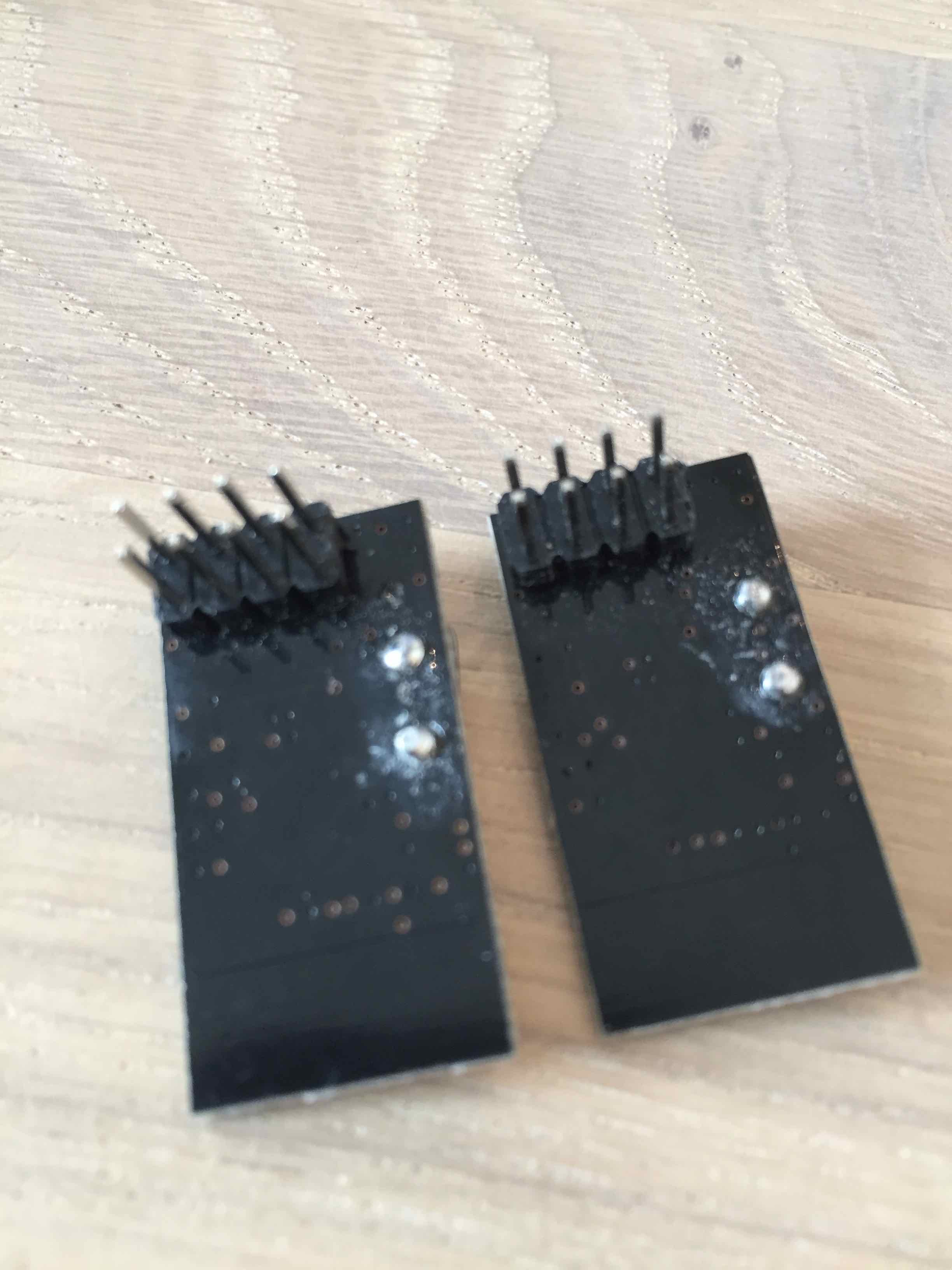
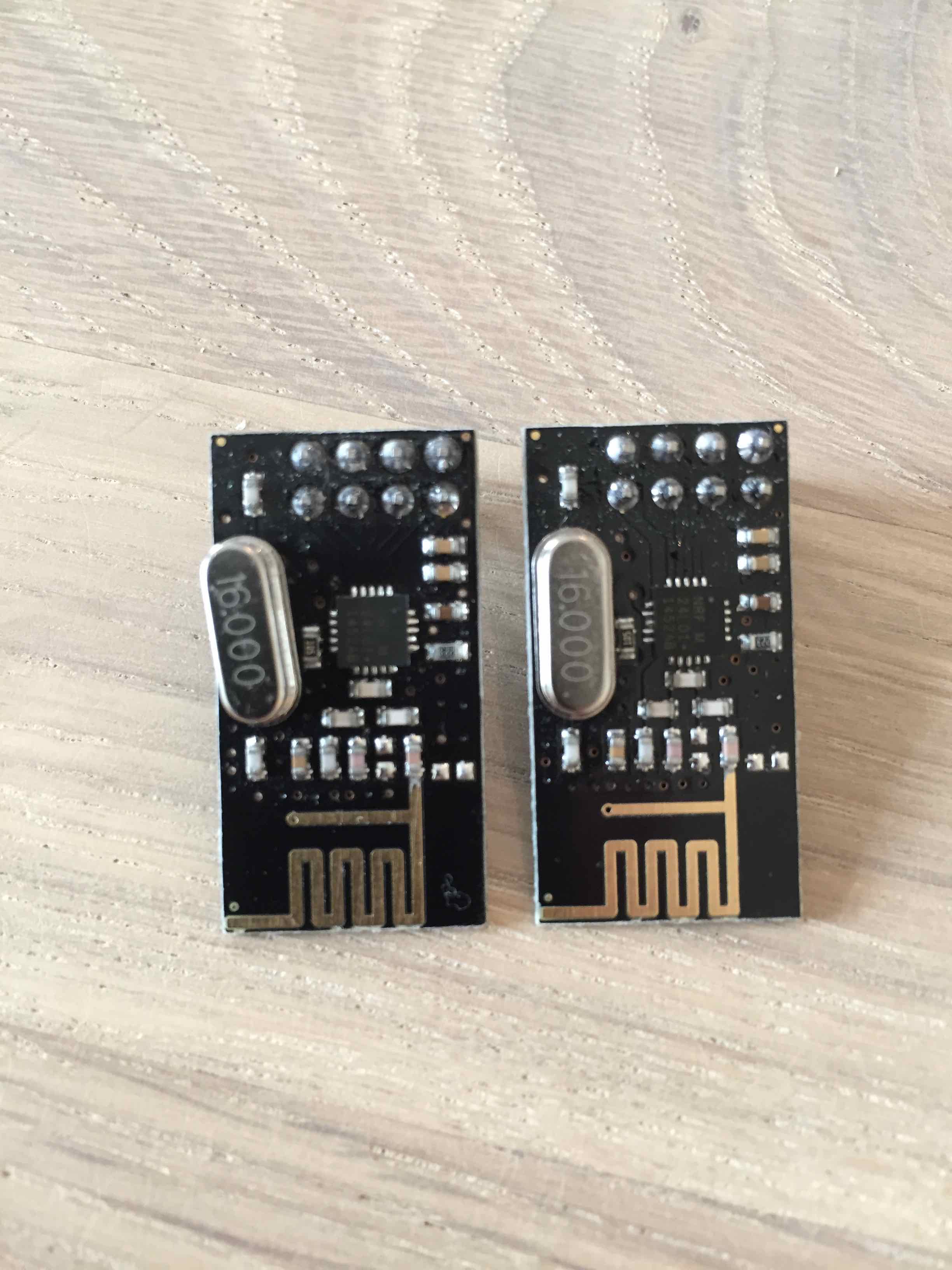
                        Fake NRF chips seems like the most plausible reason so far. The chips do look of bad quality.... but whether the chips are the issues or not is difficult to say..

                        Can you judge from the pictures?

                        1 Reply Last reply
                        0
                        • sundberg84S Offline
                          sundberg84S Offline
                          sundberg84
                          Hardware Contributor
                          wrote on last edited by sundberg84
                          #13

                          No - its not possible to say exacly. Its defenetly a fake - but how bad, not possible to say.
                          I read some days ago someone recieved a bad batch and there was no silkscreen / white markings just like you. (See image) alt text
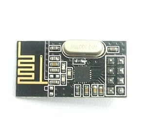
                          but I also recieved a batch yesterday without markings - and the one i used today worked great!

                          Controller: Proxmox VM - Home Assistant
                          MySensors GW: Arduino Uno - W5100 Ethernet, Gw Shield Nrf24l01+ 2,4Ghz
                          MySensors GW: Arduino Uno - Gw Shield RFM69, 433mhz
                          RFLink GW - Arduino Mega + RFLink Shield, 433mhz

                          1 Reply Last reply
                          0
                          • Christian SimonsenC Offline
                            Christian SimonsenC Offline
                            Christian Simonsen
                            wrote on last edited by Christian Simonsen
                            #14

                            Ok,

                            Is there a sketch that I can use that I can use to test/debug the NRF module specifically that might help identify what I am doing wrong or the if the module is bad?

                            I see some refer to running "Get Started".... but can't seem to find out what they are referring to...

                            1 Reply Last reply
                            0
                            • Christian SimonsenC Offline
                              Christian SimonsenC Offline
                              Christian Simonsen
                              wrote on last edited by
                              #15

                              Hi,

                              I found the TMRh20/RF24 library on GitHub and I uploaded the GetStarted sketch to the Arduino. Not sure if it is working but atleast a lot started happening in the Serial Monitor.

                              RF24/examples/GettingStarted
                              *** PRESS 'T' to begin transmitting to the other node
                              Sent response 16908288
                              Sent response 0
                              Sent response 1040677376
                              Sent response 0
                              Sent response 671495
                              Sent response 4294903807
                              Sent response 50331648
                              Sent response 50331648
                              Sent response 65536
                              Sent response 16777292
                              Sent response 0
                              Sent response 33554434
                              Sent response 0
                              Sent response 167903239
                              Sent response 167903239
                              Sent response 32639
                              Sent response 2
                              Sent response 512
                              Sent response 33554434
                              Sent response 1057423360
                              Sent response 1057423360
                              Sent response 1057161279
                              Sent response 4294967295
                              Sent response 0
                              

                              Then I pressed "T" in the Serial Monitor and then this happend:

                              *** CHANGING TO TRANSMIT ROLE -- PRESS 'R' TO SWITCH BACK
                              Now sending
                              failed
                              Failed, response timed out.
                              Now sending
                              Sent 127157552, Got response 0, Round-trip delay 1730592 microseconds
                              Now sending
                              Sent 129889960, Got response 0, Round-trip delay 3673784 microseconds
                              Now sending
                              Sent 134565556, Got response 0, Round-trip delay 4033292 microseconds
                              Now sending
                              Sent 139600664, Got response 0, Round-trip delay 4093332 microseconds
                              Now sending
                              Sent 144695808, Got response 0, Round-trip delay 16792 microseconds
                              Now sending
                              Sent 145714324, Got response 0, Round-trip delay 3975708 microseconds
                              Now sending
                              Sent 150691860, Got response 0, Round-trip delay 4035408 microseconds
                              Now sending
                              Sent 155729096, Got response 0, Round-trip delay 4196592 microseconds
                              Now sending
                              Sent 160927500, Got response 0, Round-trip delay 3815552 microseconds
                              

                              To me it seems to work..

                              1 Reply Last reply
                              0
                              • Christian SimonsenC Offline
                                Christian SimonsenC Offline
                                Christian Simonsen
                                wrote on last edited by
                                #16

                                Hi,

                                Now I have also tried the original RF24 library by ManiacBug (link). And I got this results in the Serial Terminal.

                                
                                STATUS		 = 0x00 RX_DR=0 TX_DS=0 MAX_RT=0 RX_P_NO=0 TX_FULL=0
                                RX_ADDR_P0-1	x00 = 0x0000000000 0x0000000000
                                RX_ADDR_P2-5	x00 = 0x00 0x00 0x00 0x00
                                TX_ADDR		 = 0x0000000000
                                RX_PW_P0-6	x00 = 0x00 0x00 0x00 0x00 0x00 0x00
                                EN_AA		 = 0x00
                                EN_RXADDR	x00 = 0x00
                                RF_CH		 = 0x00
                                RF_SETUP	x00 = 0x00
                                CONFIG		 = 0x00
                                DYNPD/FEATURE	x00 = 0x00 0x00
                                Data Rate	 = 1MBPS
                                Model		 = nRF24L01
                                CRC Length	 = Disabled
                                PA Power	 = PA_MIN
                                

                                From what I can understand the Arduino is able to send and receive responses (even though I only have one NRFmodule running... so not sure what is given the response to the NRF... )

                                
                                Now sending 55497...ok...Got response 4294967295, round-trip delay: 55499
                                
                                Now sending 56500...ok...Got response 4294967295, round-trip delay: 56502
                                
                                Now sending 57502...failed.
                                
                                Got response 4294967295, round-trip delay: 58083
                                
                                Now sending 59082...failed.
                                
                                Got response 4294967295, round-trip delay: 59675
                                
                                Now sending 60675...ok...Got response 4294967295, round-trip delay: 60691
                                
                                Now sending 61690...ok...Got response 4294967295, round-trip delay: 61692
                                
                                Now sending 62693...ok...Got response 4294967295, round-trip delay: 62695
                                
                                Now sending 63695...ok...Got response 4294967295, round-trip delay: 63711
                                

                                On in the other mode I'm getting this...

                                
                                Got payload 4294967295...Sent response.
                                
                                Got payload 4294967295...Sent response.
                                
                                Got payload 4294967295...Sent response.
                                
                                Got payload 4294967295...Sent response.
                                
                                Got payload 4294967295...Sent response.
                                
                                Got payload 4294967295...Sent response
                                

                                The odd part is, why do I then not get the MySensor SerialGateway sketch to work... any thoughts?

                                1 Reply Last reply
                                0
                                • naviathanN Offline
                                  naviathanN Offline
                                  naviathan
                                  wrote on last edited by
                                  #17

                                  This isn't working at all. First, yes you have fake chips, I have the same ones, but they work with the RF24 library just fine so far. Second, the payload should be either the current microseconds or a steadily incrementing number. The payload you're getting is the result of either bad power or incorrect pin out to your controller, usually the CE and CSN are wrong.

                                  1 Reply Last reply
                                  0
                                  Reply
                                  • Reply as topic
                                  Log in to reply
                                  • Oldest to Newest
                                  • Newest to Oldest
                                  • Most Votes


                                  20

                                  Online

                                  11.7k

                                  Users

                                  11.2k

                                  Topics

                                  113.1k

                                  Posts


                                  Copyright 2025 TBD   |   Forum Guidelines   |   Privacy Policy   |   Terms of Service
                                  • Login

                                  • Don't have an account? Register

                                  • Login or register to search.
                                  • First post
                                    Last post
                                  0
                                  • MySensors
                                  • OpenHardware.io
                                  • Categories
                                  • Recent
                                  • Tags
                                  • Popular