12v Solar battery monitor
-
Yes that would work. That would give you a maximum input of 20v so you will need to change relevant line in the sketch from 25000 to 20000
You can try different values on this web site. http://www.raltron.com/cust/tools/voltage_divider.asp
-
I really don't get this.
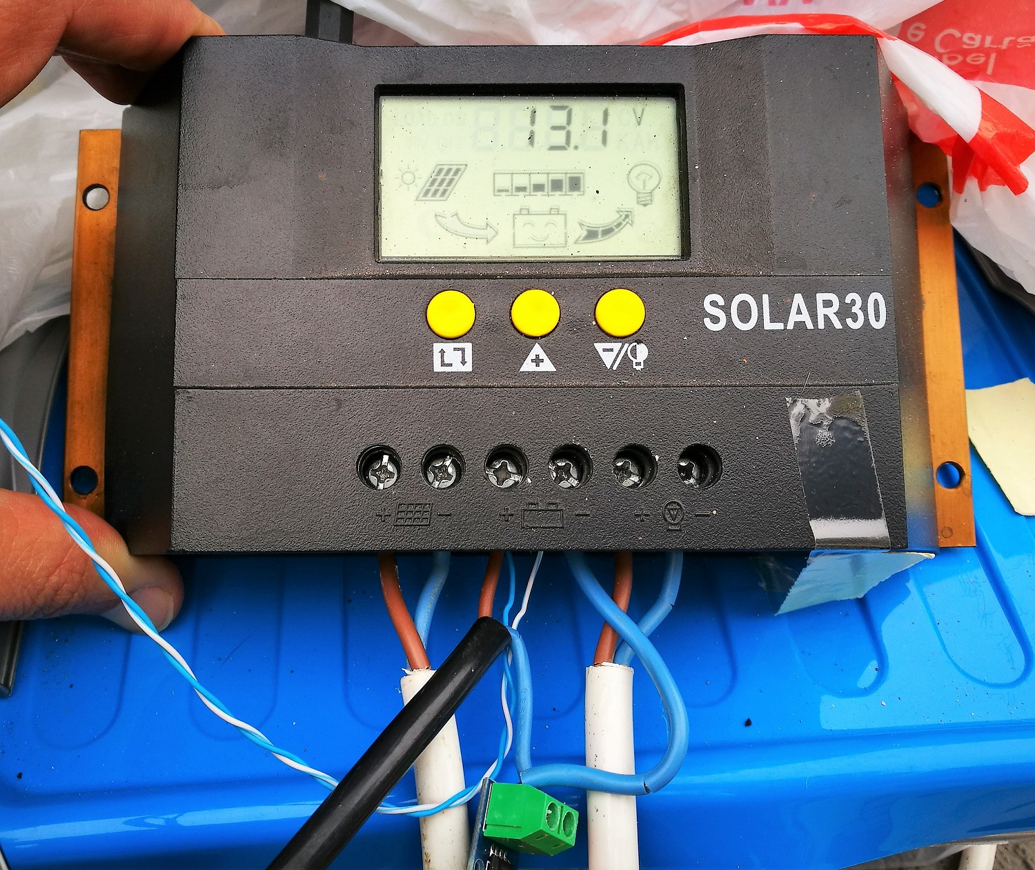
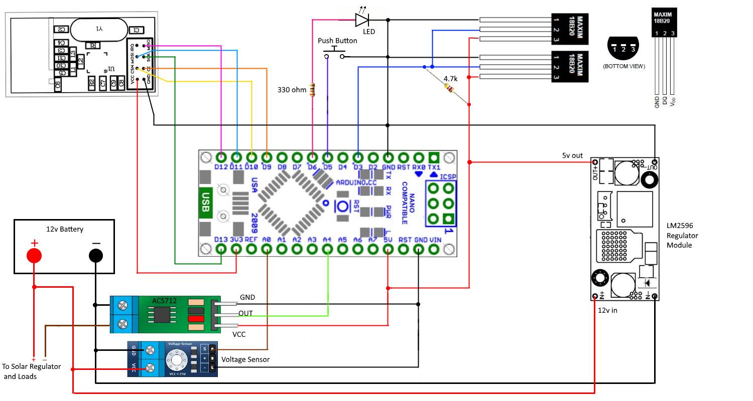
Has i can see i did everything correct but i'm still getting weard values.... In the charge regulator that i have the solar30 i'm connecting the ACS712 like you told.
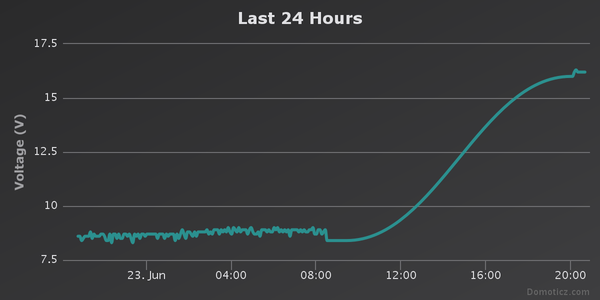
The voltage dividir i had it connected also on the battery vcc for the 30K resistor and ground on the 10K resistor, over the code i ahd change the "voltSenseMax" to 20000.With this changes the House battery went from 8.4V to 16.2V but when i make the reading off the battery with a multimeter i get 13V and also the charge regulator screen shows 13V...
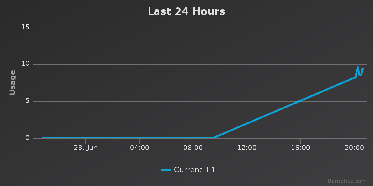
The charge current is over 0A now but is night at my place ill wait until tomorrow to see if this values change over the morning and day.
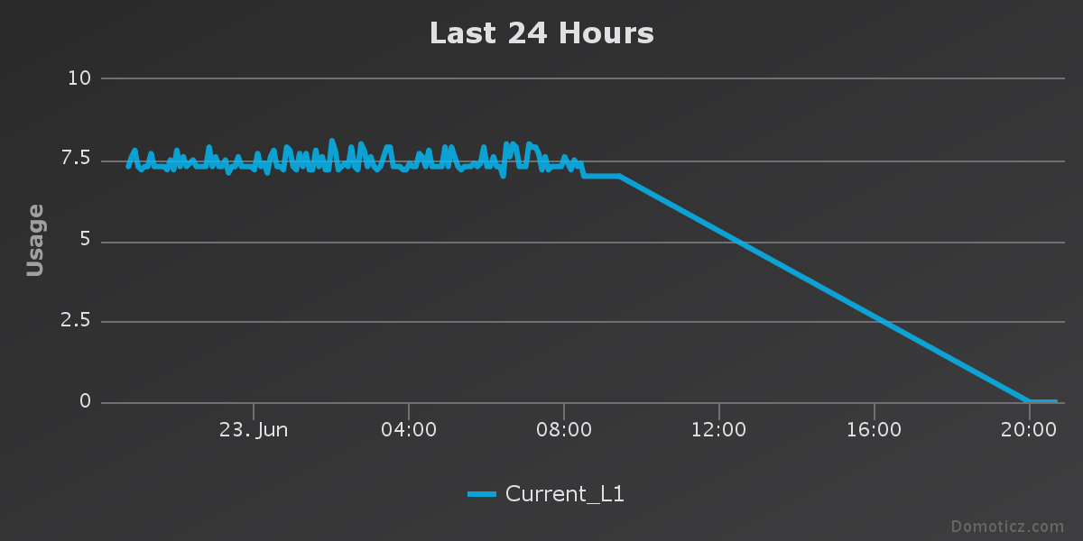
The load current is 9.1A this one i dont get it...
-
When you were measuring 13v at the battery what was the voltage at pin A0 on the arduino. You will need to compare the readings to see if the divider is working correctly. Have you removed the comments on the serial print lines , you can then check those results with your other measurements. Also check the resistance of the resistors in your voltage divider with your multimeter to make sure they are close to the values you expect.
From what I can see in the picture the asc712 looks to be hooked up OK. They are very sensitive to electromagnetic interference so you may want to try it further away from your regulator.
-
Hi.
Ok i did not measure the pin A0 when i was measuring de 13V over the battery but i can do that.I have removed the comments but i hook up the arduino in the battery box and did not look over the serie monitor on PC, once again i'll do that today.
I think the voltage divider i ok, i did a check using a 3,7V battery and the values ia had get with the voltage divider were 0,20% differente from the ones i was getting over the multimeter, 3.2V to 3.4VI'm going to mak some changes over the place were the asc712 is, i have a box on the wall 40cm to 80cm distance off the batteryes. That's were the ACS712 is going to be.
Thanks.
-
Just took the readings from pin A0 and the values are 3.2V when the battery readins says 13V.
The house battery is fix at 16V or 16.2V but i could not move the acs712 to the box i wanted it's night now and i can't see well, sow this change will be done tomorrow. While i'm wainting let's see if this 16V changes during the day off tomorrow.Well it's being dificult to get this project work like a charm but it's staring to get tune up thank's to your help Boots33.
-
I've a mistake when said 4 arduino nano with some sensors, correcting this mistake:
1º arduino nano with UV sensor;
1º arduino nano with lux sensor, pressure sensor, temp/hum sensor and one anemometer; "this is my meteo box sensor"
1º arduino nano with the acs712, voltage sensor and the dallas temperature sensor
1º arduino nano controling a rain gauge.It's 4 arduino nano with 7 sensors, i don't believe that all this put together are draining 8.6A from the battery. Isn't this a too high value ?
-
3.2v at A0 sounds about right for a 20v divider reading 13v at the battery. So your divider seems to be OK. you now need to check the results from those serial print statements and see how they compare.
The code for the voltage measurement is pretty simple with the map function doing most of the work. Not a lot to go wrong there I think. But we will know more when you get the above results.
8.6A is too high for the current. if you were drawing that much your 20ah battery would be flat in a couple of hours, so the reading is wrong. Can you check with your multimeter and see how much is being drawn. I would not think it would even be 1 amp with just 4 arduino's connected
-
With a 3.2v at A0 you should have a count of around 656 from the serial print
-
Hi once again.
Today i had to dismount all the solar system my arduino nano just died... don't now why and also the repeater node also dead...I had replaced the arduino for the solar system i had also put he battery inside my house to make all the tests.
here is the serial monitor log:Requesting temperatures...
sum count...511
mapped volts...10.0
Milliamps...-95
Requesting temperatures...
sum count...522
mapped volts...10.2
send: 6-6-3-0 s=3,c=1,t=38,pt=7,l=5,sg=0,st=ok:10.2
Milliamps...-95
Requesting temperatures...
sum count...506
mapped volts...9.9
send: 6-6-3-0 s=3,c=1,t=38,pt=7,l=5,sg=0,st=ok:9.9
Milliamps...-95
Requesting temperatures...
sum count...511
mapped volts...10.0
send: 6-6-3-0 s=3,c=1,t=38,pt=7,l=5,sg=0,st=ok:10.0
Milliamps...-95
Requesting temperatures...
sum count...511
mapped volts...10.0
Milliamps...-95
Requesting temperatures...
sum count...511
mapped volts...10.0
Milliamps...-95
Requesting temperatures...
sum count...511
mapped volts...10.0
Milliamps...-95
Requesting temperatures...One thing i had notice now is that house voltage is 10V but solar regulator and multimeter says 13V, and i had moved the acs712 away from the battery.
The test i made was one CPU fan connect to the solar regulator load, this fan is 12A - 0.25A.
Running the fan the solar regulator shows a Load off 0.1A and the arduino shows values between 0A and 0.3Asend: 6-6-3-0 s=255,c=0,t=17,pt=0,l=5,sg=0,st=ok:1.5.1
send: 6-6-3-0 s=255,c=3,t=6,pt=1,l=1,sg=0,st=ok:3
sensor started, id=6, parent=3, distance=2
send: 6-6-3-0 s=255,c=3,t=11,pt=0,l=21,sg=0,st=ok:Battery Status Sensor
send: 6-6-3-0 s=255,c=3,t=12,pt=0,l=1,sg=0,st=ok:1
send: 6-6-3-0 s=0,c=0,t=6,pt=0,l=0,sg=0,st=fail:
send: 6-6-3-0 s=1,c=0,t=6,pt=0,l=0,sg=0,st=fail:
send: 6-6-3-0 s=3,c=0,t=38,pt=0,l=0,sg=0,st=fail:
send: 6-6-3-0 s=4,c=0,t=39,pt=0,l=0,sg=0,st=fail:
send: 6-6-3-0 s=5,c=0,t=39,pt=0,l=0,sg=0,st=fail:
sum count...511
mapped volts...10.0
send: 6-6-3-0 s=3,c=1,t=38,pt=7,l=5,sg=0,st=fail:10.0
find parent
send: 6-6-255-255 s=255,c=3,t=7,pt=0,l=0,sg=0,st=bc:
Milliamps...52
send: 6-6-3-0 s=4,c=1,t=39,pt=7,l=5,sg=0,st=ok:0.1
send: 6-6-3-0 s=5,c=1,t=39,pt=2,l=2,sg=0,st=fail:0
Requesting temperatures...
send: 6-6-3-0 s=0,c=1,t=0,pt=7,l=5,sg=0,st=fail:30.3
send: 6-6-3-0 s=1,c=1,t=0,pt=7,l=5,sg=0,st=fail:-127.0
sum count...517
mapped volts...10.1
send: 6-6-3-0 s=3,c=1,t=38,pt=7,l=5,sg=0,st=ok:10.1
Milliamps...200
send: 6-6-3-0 s=4,c=1,t=39,pt=7,l=5,sg=0,st=ok:0.2
send: 6-6-3-0 s=5,c=1,t=39,pt=2,l=2,sg=0,st=ok:0
Requesting temperatures...
send: 6-6-3-0 s=0,c=1,t=0,pt=7,l=5,sg=0,st=fail:29.9
sum count...511
mapped volts...10.0
send: 6-6-3-0 s=3,c=1,t=38,pt=7,l=5,sg=0,st=ok:10.0
Milliamps...126
send: 6-6-3-0 s=4,c=1,t=39,pt=7,l=5,sg=0,st=ok:0.1
send: 6-6-3-0 s=5,c=1,t=39,pt=2,l=2,sg=0,st=ok:0
Requesting temperatures... -
OK that is good you can now see the serial print lines. The voltage conversion seems to look ok .... a count of 511 shows a voltage of 10. So now I need you to get all the readings at once
measure battery voltage
measure pin A0 voltage
and show the serial data as you have abovethen we can see where the trouble lies
-
Battery Voltage - 13.09
pin A0 - 1.055send: 6-6-3-0 s=255,c=0,t=17,pt=0,l=5,sg=0,st=ok:1.5.1
send: 6-6-3-0 s=255,c=3,t=6,pt=1,l=1,sg=0,st=fail:3
sensor started, id=6, parent=3, distance=2
send: 6-6-3-0 s=255,c=3,t=11,pt=0,l=21,sg=0,st=ok:Battery Status Sensor
send: 6-6-3-0 s=255,c=3,t=12,pt=0,l=1,sg=0,st=fail:1
send: 6-6-3-0 s=0,c=0,t=6,pt=0,l=0,sg=0,st=fail:
send: 6-6-3-0 s=1,c=0,t=6,pt=0,l=0,sg=0,st=ok:
send: 6-6-3-0 s=3,c=0,t=38,pt=0,l=0,sg=0,st=fail:
send: 6-6-3-0 s=4,c=0,t=39,pt=0,l=0,sg=0,st=ok:
send: 6-6-3-0 s=5,c=0,t=39,pt=0,l=0,sg=0,st=fail:
sum count...532
mapped volts...10.4
send: 6-6-3-0 s=3,c=1,t=38,pt=7,l=5,sg=0,st=fail:10.4
Milliamps...347
send: 6-6-3-0 s=4,c=1,t=39,pt=7,l=5,sg=0,st=fail:0.3
send: 6-6-3-0 s=5,c=1,t=39,pt=2,l=2,sg=0,st=fail:0
Requesting temperatures...
send: 6-6-3-0 s=0,c=1,t=0,pt=7,l=5,sg=0,st=fail:29.5
send: 6-6-3-0 s=1,c=1,t=0,pt=7,l=5,sg=0,st=ok:-127.0
sum count...513
mapped volts...10.0
send: 6-6-3-0 s=3,c=1,t=38,pt=7,l=5,sg=0,st=ok:10.0
Milliamps...347
Requesting temperatures...
send: 6-6-3-0 s=0,c=1,t=0,pt=7,l=5,sg=0,st=ok:29.4
sum count...519
mapped volts...10.1
send: 6-6-3-0 s=3,c=1,t=38,pt=7,l=5,sg=0,st=ok:10.1
Milliamps...421
send: 6-6-3-0 s=4,c=1,t=39,pt=7,l=5,sg=0,st=ok:0.4
send: 6-6-3-0 s=5,c=1,t=39,pt=2,l=2,sg=0,st=ok:0
Requesting temperatures...
send: 6-6-3-0 s=0,c=1,t=0,pt=7,l=5,sg=0,st=fail:29.5
sum count...511
mapped volts...10.0
send: 6-6-3-0 s=3,c=1,t=38,pt=7,l=5,sg=0,st=ok:10.0
Milliamps...347
send: 6-6-3-0 s=4,c=1,t=39,pt=7,l=5,sg=0,st=ok:0.3
send: 6-6-3-0 s=5,c=1,t=39,pt=2,l=2,sg=0,st=ok:0
Requesting temperatures...
send: 6-6-3-0 s=0,c=1,t=0,pt=7,l=5,sg=0,st=fail:29.4
sum count...511
mapped volts...10.0
Milliamps...347
Requesting temperatures...
send: 6-6-3-0 s=0,c=1,t=0,pt=7,l=5,sg=0,st=ok:29.5
sum count...511
mapped volts...10.0
Milliamps...200
send: 6-6-3-0 s=4,c=1,t=39,pt=7,l=5,sg=0,st=ok:0.2
send: 6-6-3-0 s=5,c=1,t=39,pt=2,l=2,sg=0,st=ok:0
Requesting temperatures...
sum count...485
mapped volts...9.5
send: 6-6-3-0 s=3,c=1,t=38,pt=7,l=5,sg=0,st=ok:9.5
Milliamps...273
send: 6-6-3-0 s=4,c=1,t=39,pt=7,l=5,sg=0,st=ok:0.3
send: 6-6-3-0 s=5,c=1,t=39,pt=2,l=2,sg=0,st=ok:0
Requesting temperatures...
sum count...510
mapped volts...10.0
send: 6-6-3-0 s=3,c=1,t=38,pt=7,l=5,sg=0,st=ok:10.0
Milliamps...347
send: 6-6-3-0 s=4,c=1,t=39,pt=7,l=5,sg=0,st=ok:0.3
send: 6-6-3-0 s=5,c=1,t=39,pt=2,l=2,sg=0,st=fail:0
Requesting temperatures...
sum count...501
mapped volts...9.8
send: 6-6-3-0 s=3,c=1,t=38,pt=7,l=5,sg=0,st=ok:9.8
Milliamps...347
Requesting temperatures...
sum count...511
mapped volts...10.0
send: 6-6-3-0 s=3,c=1,t=38,pt=7,l=5,sg=0,st=ok:10.0
Milliamps...347
Requesting temperatures...Once again i had connect the 12v fan to the load of the charge regulator
-
If you are still using the 20v divider, with a battery voltage of 13.09 you should have a voltage of 3.27 at pin A0
1.055v is way too low, check you connections to make sure they are tight. measure the voltage at the divider input to make sure the 13v is there as well.
post results again
-
3.29v It's the value i'm getting at the end off the 20v divider but at pin A0 i have 1.23V
Requesting temperatures...
sum count...198
mapped volts...3.9
send: 6-6-3-0 s=3,c=1,t=38,pt=7,l=5,sg=0,st=ok:3.9
Milliamps...200
send: 6-6-3-0 s=4,c=1,t=39,pt=7,l=5,sg=0,st=ok:0.2
send: 6-6-3-0 s=5,c=1,t=39,pt=2,l=2,sg=0,st=ok:0
Requesting temperatures...
sum count...511
mapped volts...10.0
send: 6-6-3-0 s=3,c=1,t=38,pt=7,l=5,sg=0,st=ok:10.0
Milliamps...126
send: 6-6-3-0 s=4,c=1,t=39,pt=7,l=5,sg=0,st=ok:0.1
send: 6-6-3-0 s=5,c=1,t=39,pt=2,l=2,sg=0,st=ok:0
Requesting temperatures...
sum count...511
mapped volts...10.0
Milliamps...-21
send: 6-6-3-0 s=4,c=1,t=39,pt=2,l=2,sg=0,st=ok:0
send: 6-6-3-0 s=5,c=1,t=39,pt=7,l=5,sg=0,st=fail:0.0
Requesting temperatures...
sum count...520
mapped volts...10.2
send: 6-6-3-0 s=3,c=1,t=38,pt=7,l=5,sg=0,st=ok:10.2
Milliamps...126
send: 6-6-3-0 s=4,c=1,t=39,pt=7,l=5,sg=0,st=ok:0.1
send: 6-6-3-0 s=5,c=1,t=39,pt=2,l=2,sg=0,st=fail:0
Requesting temperatures...
sum count...533
mapped volts...10.4
send: 6-6-3-0 s=3,c=1,t=38,pt=7,l=5,sg=0,st=ok:10.4
Milliamps...52
send: 6-6-3-0 s=4,c=1,t=39,pt=7,l=5,sg=0,st=ok:0.1
send: 6-6-3-0 s=5,c=1,t=39,pt=2,l=2,sg=0,st=ok:0
Requesting temperatures...
sum count...511
mapped volts...10.0
send: 6-6-3-0 s=3,c=1,t=38,pt=7,l=5,sg=0,st=ok:10.0
Milliamps...-21
send: 6-6-3-0 s=4,c=1,t=39,pt=2,l=2,sg=0,st=ok:0
send: 6-6-3-0 s=5,c=1,t=39,pt=7,l=5,sg=0,st=ok:0.0
Requesting temperatures...
sum count...511
mapped volts...10.0
Milliamps...200
send: 6-6-3-0 s=4,c=1,t=39,pt=7,l=5,sg=0,st=ok:0.2
send: 6-6-3-0 s=5,c=1,t=39,pt=2,l=2,sg=0,st=ok:0
Requesting temperatures... -
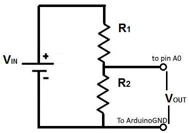
then that is where the problem may be. the output of the divider should be connected to A0 so they should be the same. look at the diagram below
-
I think the problem is fix now.
bad cable between ground from 20v divider and arduino ground.
now i'm getting the same value at pin a0here are the new logs
send: 6-6-3-0 s=255,c=3,t=11,pt=0,l=21,sg=0,st=ok:Battery Status Sensor
send: 6-6-3-0 s=255,c=3,t=12,pt=0,l=1,sg=0,st=ok:1
send: 6-6-3-0 s=0,c=0,t=6,pt=0,l=0,sg=0,st=ok:
send: 6-6-3-0 s=1,c=0,t=6,pt=0,l=0,sg=0,st=fail:
send: 6-6-3-0 s=3,c=0,t=38,pt=0,l=0,sg=0,st=fail:
send: 6-6-3-0 s=4,c=0,t=39,pt=0,l=0,sg=0,st=fail:
send: 6-6-3-0 s=5,c=0,t=39,pt=0,l=0,sg=0,st=ok:
sum count...715
mapped volts...14.0
send: 6-6-3-0 s=3,c=1,t=38,pt=7,l=5,sg=0,st=ok:14.0
Milliamps...-21
send: 6-6-3-0 s=4,c=1,t=39,pt=2,l=2,sg=0,st=ok:0
send: 6-6-3-0 s=5,c=1,t=39,pt=7,l=5,sg=0,st=ok:0.0
Requesting temperatures...
send: 6-6-3-0 s=0,c=1,t=0,pt=7,l=5,sg=0,st=ok:29.3
send: 6-6-3-0 s=1,c=1,t=0,pt=7,l=5,sg=0,st=ok:-127.0
sum count...710
mapped volts...13.9
send: 6-6-3-0 s=3,c=1,t=38,pt=7,l=5,sg=0,st=ok:13.9
Milliamps...52
send: 6-6-3-0 s=4,c=1,t=39,pt=7,l=5,sg=0,st=ok:0.1
send: 6-6-3-0 s=5,c=1,t=39,pt=2,l=2,sg=0,st=ok:0
Requesting temperatures...
sum count...713
mapped volts...13.9
send: 6-6-3-0 s=3,c=1,t=38,pt=7,l=5,sg=0,st=ok:13.9
Milliamps...-21
send: 6-6-3-0 s=4,c=1,t=39,pt=2,l=2,sg=0,st=ok:0
send: 6-6-3-0 s=5,c=1,t=39,pt=7,l=5,sg=0,st=ok:0.0
Requesting temperatures...
sum count...711
mapped volts...13.9
send: 6-6-3-0 s=3,c=1,t=38,pt=7,l=5,sg=0,st=ok:13.9
Milliamps...200
send: 6-6-3-0 s=4,c=1,t=39,pt=7,l=5,sg=0,st=ok:0.2
send: 6-6-3-0 s=5,c=1,t=39,pt=2,l=2,sg=0,st=ok:0
Requesting temperatures...
sum count...712
mapped volts...13.9
send: 6-6-3-0 s=3,c=1,t=38,pt=7,l=5,sg=0,st=ok:13.9
Milliamps...200
Requesting temperatures...
sum count...709
mapped volts...13.9
send: 6-6-3-0 s=3,c=1,t=38,pt=7,l=5,sg=0,st=ok:13.9
Milliamps...126
send: 6-6-3-0 s=4,c=1,t=39,pt=7,l=5,sg=0,st=ok:0.1
send: 6-6-3-0 s=5,c=1,t=39,pt=2,l=2,sg=0,st=ok:0
Requesting temperatures...
sum count...713
mapped volts...13.9
send: 6-6-3-0 s=3,c=1,t=38,pt=7,l=5,sg=0,st=ok:13.9
Milliamps...126
Requesting temperatures...still using the cpu fan 12v 0.25A pin A0 3.28V
Mapped volts 13.9 it's very near the 13.2V the multimeter gives at the battery.
This is the best results i had until now.Thanks boots33 for all your help.
-
Great to hear you have found the problem. If the voltages are not quite correct you can adjust the 20000 value up or down a bit as needed to fine tune the output result.
You can use these to check for the problem
for a 20v divider
20/1024 = .019531
to get the count that should be shown by serial print...: batteryvoltage / .019531
so with your reading 13.09 / .019531 = 670
That means you should see a count of 670 from the serial printto get the voltage that should be at pin A0...: count * .00488
670 * .00488 = 3.27v
to get the map result
20000/1024 = 19.531mv or .01953v
so 670 * .01953 = 13.1v
-
The best way to setup the acs712 is to put it where it is going to be mounted but have no current going through it. (you can just disconnect one power lead) it should show a reading close to zero.
If not push the button and hold till the led flashes (may take a while depending on how much delay you are using) once the led flashes you can let go of the button and the offset to zero the reading will be applied. This offset will also be saved in the arduino eeprom so it will be reloaded if the arduino is rebooted etc.
then the readings should be very close to zero.
you can now reconnect and it should give you the correct reading. -
Hallo
Mein Englisch ist nicht so gut.
Ich habe versucht das Projekt nach zu bauen. Den Button brauche ich (denke ich) nicht, dafür habe ich das script jedoch um 2 weitere current und voltage Sensoren erweitert. Das Ziel ist 3 mal Current und 3 mal Volt als Ergebnis zu bekommen. Ich habe 30A Sensoren und einen 30A Laderegler. Dazwischen sind jeweils 30A Sicherungen.
Leider kommt in Domoticz aber nur ein mal Volt und 2 mal Current an. Leider habe ich auch nicht wirklich viel Ahnung vom Programmieren. Könnte hier mal jemand über den Sketch gucken um zu sehen ob ich einen Fehler darin habe?/*Sketch for a MySensor node to monitor a 12v battery with a solar panel for charging * The node monitors battery voltage,current into and out of the battery, ambient temperature and battery temperature. * 2 x DS18b20 dallas temperature ic's their data pins connected to arduino digital pin 3 * 1 x ACS712 current sensor module connected to arduino analog pin A4 * 1 x 25v voltage sensor module connected to arduino analog pin A0 * 1 x nRF24L01+ 2.4ghz tranceiver connected as per the MySensors web site. * 1 x LED connected via a 330 ohm resistor to pin 6 * 1 x push button connected to pin 5 */ #include <MySensor.h> #include <SPI.h> #include <OneWire.h> #include <DallasTemperature.h> #define ONE_WIRE_BUS 3 // Ds18b20 data wire is connected to digital pin 3 on the Arduino #define ID_S_TEMPA 0 // First temp device #define ID_S_TEMPB 1 // second temp device #define ID_S_MULTIMETERV1 3 // Multimeter device for voltage measurement #define ID_S_MULTIMETERC1 4 // Multimeter device for positive current measurement #define ID_S_MULTIMETERC11 5 // Multimeter device for negative current measurement #define ID_S_MULTIMETERV2 3 // Multimeter device for voltage measurement #define ID_S_MULTIMETERC2 4 // Multimeter device for positive current measurement #define ID_S_MULTIMETERC12 5 // Multimeter device for negative current measurement #define ID_S_MULTIMETERV3 6 // Multimeter device for voltage measurement #define ID_S_MULTIMETERC3 7 // Multimeter device for positive current measurement #define ID_S_MULTIMETERC13 8 #define NUM_SAMPLES 10 // number of analog voltage samples to take per reading int ledPin = 6; // the pin for the LED int buttonPin = 5; // the input pin for offset pushbutton int buttonState = 0; // variable for reading the pin status unsigned long SLEEP_TIME = 30000; // Sleep time between reads (in milliseconds) int lastmilli1 = 25000; // set to an arbitary number outside of expected current sensor range to ensure a change when first run int lastmilli2 = 25000; // set to an arbitary number outside of expected current sensor range to ensure a change when first run int lastmilli3 = 25000; // set to an arbitary number outside of expected current sensor range to ensure a change when first run float sensitivity = 66 ; //change this to 185 for ACS712-5 or to 100 for ACS712-20A or to 66 for ACS712-30A int VQ = 0; //Placeholder for quiescent voltage calculations int ACSPin1 = A4; // Analog pin number the ACS712 data pin connects to int ACSPin2 = A5; // Analog pin number the ACS712 data pin connects to int ACSPin3 = A3; // Analog pin number the ACS712 data pin connects to float lastTemperature[2]; //Array to hold the last temp readings sent to gateway, only send new data if different int sum = 0; // sum of voltage samples taken unsigned char sample_count = 0; // current sample number int lastVoltage1 = 30000; // set to an arbitary number outside of expected voltage sensor range to ensure a change when first run int lastVoltage2 = 30000; // set to an arbitary number outside of expected voltage sensor range to ensure a change when first run int lastVoltage3 = 30000; // set to an arbitary number outside of expected voltage sensor range to ensure a change when first run int voltagePin1 = A0; // analog pin voltage sensor or voltage divider is connected to int voltagePin2 = A1; // analog pin voltage sensor or voltage divider is connected to int voltagePin3 = A2; // analog pin voltage sensor or voltage divider is connected to int voltSense1Max = 25000; // set to the maximum input voltage in millivolts of your voltage divider input int voltSense2Max = 25000; // set to the maximum input voltage in millivolts of your voltage divider input int voltSense3Max = 25000; // set to the maximum input voltage in millivolts of your voltage divider input OneWire oneWire(ONE_WIRE_BUS); // Setup a oneWire instance to communicate with any OneWire devices (not just Maxim/Dallas temperature ICs) DallasTemperature sensors(&oneWire); // Pass our oneWire reference to Dallas Temperature. MySensor gw; // ------ Initialize messages ------- MyMessage msg(0,V_TEMP); MyMessage msg_S_MULTIMETERv1(ID_S_MULTIMETERV1,V_VOLTAGE); MyMessage msg_S_MULTIMETERc1(ID_S_MULTIMETERC1,V_CURRENT); MyMessage msg_S_MULTIMETERc11(ID_S_MULTIMETERC11,V_CURRENT); MyMessage msg_S_MULTIMETERv2(ID_S_MULTIMETERV2,V_VOLTAGE); MyMessage msg_S_MULTIMETERc2(ID_S_MULTIMETERC2,V_CURRENT); MyMessage msg_S_MULTIMETERc12(ID_S_MULTIMETERC12,V_CURRENT); MyMessage msg_S_MULTIMETERv3(ID_S_MULTIMETERV3,V_VOLTAGE); MyMessage msg_S_MULTIMETERc3(ID_S_MULTIMETERC3,V_CURRENT); MyMessage msg_S_MULTIMETERc13(ID_S_MULTIMETERC13,V_CURRENT); void setup() { sensors.begin(); // Start up the onewire library gw.begin(); // Startup and initialize MySensors library. Set callback for incoming messages. gw.sendSketchInfo("Battery Status Sensor", "1"); // Send the sketch version information to the gateway and Controller // ------ Present all sensors to controller ------ gw.present(ID_S_TEMPA, S_TEMP); gw.present(ID_S_TEMPB, S_TEMP); gw.present(ID_S_MULTIMETERV1,V_VOLTAGE); gw.present(ID_S_MULTIMETERC1,V_CURRENT); gw.present(ID_S_MULTIMETERC11,V_CURRENT); gw.present(ID_S_MULTIMETERV2,V_VOLTAGE); gw.present(ID_S_MULTIMETERC2,V_CURRENT); gw.present(ID_S_MULTIMETERC12,V_CURRENT); gw.present(ID_S_MULTIMETERV3,V_VOLTAGE); gw.present(ID_S_MULTIMETERC3,V_CURRENT); gw.present(ID_S_MULTIMETERC13,V_CURRENT); pinMode(buttonPin, INPUT_PULLUP); // Set buttonPin as input and turn on internal pull up resistor pinMode(ledPin, OUTPUT); // Set ledPin as output digitalWrite(ledPin, LOW); // Make sure ledPin is off // ------ load offset for current sensor int validCheck = gw.loadState(0); if (validCheck == 120){ // check to see if valid data exists VQ = gw.loadState(1); // Load count offset into VQ // Serial.print(" positive VQ offset loaded..."); Serial.println(VQ); } else if (validCheck == 125) { VQ = -abs(gw.loadState(1)); // Serial.print(" negative VQ offset loaded..."); Serial.println(VQ); } else { // Serial.println("VQ offset not set"); } delay(500); } void loop() { buttonState = digitalRead(buttonPin); //Serial.print("buttonstate..."); Serial.println(buttonState); if (buttonState == LOW) { VQ = determineVQ(ACSPin1); //Returns the offset count needed to show zero with no load if (VQ >= 0 && VQ < 255) { //check for valid data. VQ is positive number gw.saveState(0, 120); // Store 120 value in eeprom position 0. use this to check for valid data at boot gw.saveState(1, VQ); // Store offset count in eeprom. in case of re-boot } else if (VQ < 0 && VQ > -255) { // VQ is a negative number. negatives cannot be stored in eeprom gw.saveState(0, 125); // Store 125 value in eeprom position 0. use this to check for valid data at boot gw.saveState(1, abs(VQ)); // convert VQ to positive and Store offset count in eeprom. in case of re-boot } } // ------------------ Start voltage 1 readings -------------------- sample_count = 0; sum = 0; while (sample_count < NUM_SAMPLES) { // take a number of voltage samples sum += analogRead(voltagePin1); sample_count++; delay(10); } //Serial.print("sum count..."); Serial.println((sum / NUM_SAMPLES)); // print the count result. will be between 0 and 1023 int voltage1I = map(sum/NUM_SAMPLES,0,1023,0,voltSense1Max); // map the reading and get our result in millivolts //Serial.print("mapped volts..."); Serial.println(voltageI / 1000.0, 1); // convert millivolts back to volts and print. the 1 at the end determines how many decimal places to show if ( voltage1I != lastVoltage1) { // check if we have a new value. only send data if it is different gw.send(msg_S_MULTIMETERv1.set(voltage1I / 1000.0, 1)); // voltagel is in millivolts so we divide by 1000 to convert back to volts and // send voltage message to gateway with 1 decimal place lastVoltage1 = voltage1I; // copy the current voltage reading for testing on the next loop } //--------------------Start Current 1 readings--------------------------------- int milli1 = readCurrent(ACSPin1); // take a reading from the ACS712 and send to the readcurrent function //Serial.print("Milliamps..."); Serial.println(milli); // print the value (in milliamps) returned if ( milli1 != lastmilli1) // check if value has changed { if ( milli1 > 0) // Battery is charging { gw.send(msg_S_MULTIMETERc1.set(milli1/1000.0, 1)); // Send new data to charging amp device gw.send(msg_S_MULTIMETERc11.set(0)); // set the dis-charging amp device to zero lastmilli1 = milli1; } else if (milli1 < 0) // Battery is discharging { gw.send(msg_S_MULTIMETERc1.set(0)); // set the charging amp device to zero gw.send(msg_S_MULTIMETERc11.set(abs(milli1)/1000.0, 1)); // use abs(milli) to Send a positive number to dis-charging amp device lastmilli1 = milli1; } else // No current flowing, set both to zero { gw.send(msg_S_MULTIMETERc1.set(0)); gw.send(msg_S_MULTIMETERc11.set(0)); lastmilli1 = milli1; } } //----------------------Teperature readings start------------------------ Serial.println(" Requesting temperatures..."); // Fetch temperatures from Dallas sensors sensors.requestTemperatures(); // call sensors.requestTemperatures() to issue a global temperature request to all devices on the bus // ------- query conversion time and sleep until conversion completed ------ int16_t conversionTime = sensors.millisToWaitForConversion(sensors.getResolution()); gw.sleep(conversionTime); for (int i=0; i<2; i++) { // Serial.print("Temperature for Device: ");Serial.print(i);Serial.print(" is: "); // Serial.println(sensors.getTempCByIndex(i)); // Why "byIndex"? // You can have more than one IC on the same bus. // 0 refers to the first IC on the wire float temperature = static_cast<float>(static_cast<int>((sensors.getTempCByIndex(i)) * 10.)) / 10.; // Fetch and round temperature to one decimal in celcius if (lastTemperature[i] != temperature) // check for a changed temperature reading { gw.send(msg.setSensor(i).set(temperature,1)); // Send in the new temperature lastTemperature[i]=temperature; // Save new temperatures for next compare } } // ------------------ Start 2 voltage readings -------------------- sample_count = 0; sum = 0; while (sample_count < NUM_SAMPLES) { // take a number of voltage samples sum += analogRead(voltagePin2); sample_count++; delay(10); } //Serial.print("sum count..."); Serial.println((sum / NUM_SAMPLES)); // print the count result. will be between 0 and 1023 int voltage2I = map(sum/NUM_SAMPLES,0,1023,0,voltSense2Max); // map the reading and get our result in millivolts //Serial.print("mapped volts..."); Serial.println(voltageI / 1000.0, 1); // convert millivolts back to volts and print. the 1 at the end determines how many decimal places to show if ( voltage2I != lastVoltage2) { // check if we have a new value. only send data if it is different gw.send(msg_S_MULTIMETERv2.set(voltage2I / 1000.0, 1)); // voltagel is in millivolts so we divide by 1000 to convert back to volts and // send voltage message to gateway with 1 decimal place lastVoltage2 = voltage2I; // copy the current voltage reading for testing on the next loop } //--------------------Start Current 2 readings--------------------------------- int milli2 = readCurrent(ACSPin2); // take a reading from the ACS712 and send to the readcurrent function //Serial.print("Milliamps..."); Serial.println(milli); // print the value (in milliamps) returned if ( milli2 != lastmilli2) // check if value has changed { if ( milli2 > 0) // Battery is charging { gw.send(msg_S_MULTIMETERc2.set(milli2/1000.0, 1)); // Send new data to charging amp device gw.send(msg_S_MULTIMETERc12.set(0)); // set the dis-charging amp device to zero lastmilli2 = milli2; } else if (milli1 < 0) // Battery is discharging { gw.send(msg_S_MULTIMETERc2.set(0)); // set the charging amp device to zero gw.send(msg_S_MULTIMETERc12.set(abs(milli2)/1000.0, 1)); // use abs(milli) to Send a positive number to dis-charging amp device lastmilli2 = milli2; } else // No current flowing, set both to zero { gw.send(msg_S_MULTIMETERc2.set(0)); gw.send(msg_S_MULTIMETERc12.set(0)); lastmilli2 = milli2; } } // ------------------ Start voltage 3 readings -------------------- sample_count = 0; sum = 0; while (sample_count < NUM_SAMPLES) { // take a number of voltage samples sum += analogRead(voltagePin3); sample_count++; delay(10); } //Serial.print("sum count..."); Serial.println((sum / NUM_SAMPLES)); // print the count result. will be between 0 and 1023 int voltage3I = map(sum/NUM_SAMPLES,0,1023,0,voltSense3Max); // map the reading and get our result in millivolts //Serial.print("mapped volts..."); Serial.println(voltageI / 1000.0, 1); // convert millivolts back to volts and print. the 1 at the end determines how many decimal places to show if ( voltage3I != lastVoltage3) { // check if we have a new value. only send data if it is different gw.send(msg_S_MULTIMETERv3.set(voltage3I / 1000.0, 1)); // voltagel is in millivolts so we divide by 1000 to convert back to volts and // send voltage message to gateway with 1 decimal place lastVoltage3 = voltage3I; // copy the current voltage reading for testing on the next loop } //--------------------Start Current 3 readings--------------------------------- int milli3 = readCurrent(ACSPin3); // take a reading from the ACS712 and send to the readcurrent function //Serial.print("Milliamps..."); Serial.println(milli); // print the value (in milliamps) returned if ( milli3 != lastmilli3) // check if value has changed { if ( milli3 > 0) // Battery is charging { gw.send(msg_S_MULTIMETERc3.set(milli3/1000.0, 1)); // Send new data to charging amp device gw.send(msg_S_MULTIMETERc13.set(0)); // set the dis-charging amp device to zero lastmilli3 = milli3; } else if (milli3 < 0) // Battery is discharging { gw.send(msg_S_MULTIMETERc3.set(0)); // set the charging amp device to zero gw.send(msg_S_MULTIMETERc13.set(abs(milli3)/1000.0, 1)); // use abs(milli) to Send a positive number to dis-charging amp device lastmilli3 = milli3; } else // No current flowing, set both to zero { gw.send(msg_S_MULTIMETERc3.set(0)); gw.send(msg_S_MULTIMETERc13.set(0)); lastmilli3 = milli3; } } gw.sleep(SLEEP_TIME); } /*-------------- Function to get the offset required for ACS712 to show zero with no current flowing -----------------*/ int determineVQ(int PIN) { digitalWrite(ledPin, HIGH); // Turn on LED to indicate offset being calculated delay(500); // Delay to hold LED on digitalWrite(ledPin, LOW); // Turn off LED delay(150); // Delay to let readings stabilise // Serial.print("estimating avg. quiscent voltage:"); long acsCount = 0; for (int i=0; i<5000; i++) //read 5000 samples to stabilise value { acsCount += analogRead(PIN); // read the count value between 0 and 1023 and add it to acsCount delay(1); } acsCount /= 5000; // acsCount now eaquals the average of the 5000 readings taken // Serial.print(map(acsCount, 0, 1023, 0, 5000));Serial.println(" mV"); //Print the avg in millivolts // Serial.print("acsCount:");Serial.println(acsCount); //Print the actual count value return int(acsCount - 512); // return the count difference. 512 is the count for 2.5v which is what the reading should be with no current flow } /*--------------- Function to read current flowing ------------------*/ int readCurrent(int PIN) { int count = 0; for (int i=0; i<5; i++) //read 5 analog count samples to stabilise value { count += analogRead(PIN) - VQ; //subtract the offset count VQ to improve accuracy delay(1); // Serial.print("raw count..."); Serial.println(count); } /* Notes on the conversion below * .00488 is the volt value per count of the arduino adc. The analog pin measures from 0 to 5 volt and then assigns the result to * a count from 0 to 1023, thats 1024 counts including zero. If we devide 5v by 1024 we get .oo488 volts for each count. * * The (count/5) just gets us the average of our 5 count samples. * * So after the first part of the equation (.00488 * (count/5) is complete we have converted our count reading into volts. * * The ACS712 can measure current flow in both directions so it outputs a voltage of 2.5v as it's center point (when no current is flowing). * To allow for this offset we must subtract the 2.5v to center our voltage reading. * * Thats what the next part does (.00488 * (count/5)) - 2.5) After this is complete we are left with either a negative or positive voltage * reading or a reading of zero for no current flow. * * NOTE: While the ACS712 is a 5v device it does not use the full 0 to 5v for it's output. The datasheet shows the 20A version has a sensitivity of * 100mv per amp, so if we multiply 100mv by 20 we get 2v. That means the 20A ACS712 has an output range from .5v to 4.5v. * * So to convert our reading in volts to a reading in amps we need to add the last part ((.00488 * (count/5)) - 2.5)/(sensitivity/1000). * The variable sensitivity is defined at the begining of the sketch and holds the ACS712 sensitvity amount, it is stored in millivolts. * That is 66mv for the 30amp, 100mv for the 20amp and 185mv for the 5amp. As sensitivity is in millivolts we need to devide it by 1000 * to convert it back to volts so we can use it in the equation. * * Now we have our Amps value stored in the float amps. Integers are much easier to work with when checking for zero so we multiply by 1000 * to convert it to milliamps and return it as an integer. */ //Serial.print("VQ = ..."); Serial.println(VQ); //Serial.print("current count..."); Serial.println(count/5); //Serial.print("map milliamps..."); Serial.println(map((count/5), 102, 922, -20000, 20000)); float amps = ((.00488 * (count/5)) - 2.5) / (sensitivity/1000); // Serial.print("float amps..."); Serial.println(amps, 1); return int (amps * 1000); // convert to milliamps and return as an integer } Insert Code HereEnglish:
Hello
My English is not that good.
I tried to build the project. The button I need (I think) not, but I have extended the script, however, by 2 more current and voltage sensors. The goal is to get 3 times Current and 3 times Volt as a result. I have 30A sensors and a 30A charger. In between are 30A fuses.
Unfortunately in Domoticz but only one time Volt and 2 times Current. Unfortunately I have not really much idea of the programming. Could someone here over the sketch look around to see if I have a mistake in it?do i -
Hallo
Mein Englisch ist nicht so gut.
Ich habe versucht das Projekt nach zu bauen. Den Button brauche ich (denke ich) nicht, dafür habe ich das script jedoch um 2 weitere current und voltage Sensoren erweitert. Das Ziel ist 3 mal Current und 3 mal Volt als Ergebnis zu bekommen. Ich habe 30A Sensoren und einen 30A Laderegler. Dazwischen sind jeweils 30A Sicherungen.
Leider kommt in Domoticz aber nur ein mal Volt und 2 mal Current an. Leider habe ich auch nicht wirklich viel Ahnung vom Programmieren. Könnte hier mal jemand über den Sketch gucken um zu sehen ob ich einen Fehler darin habe?/*Sketch for a MySensor node to monitor a 12v battery with a solar panel for charging * The node monitors battery voltage,current into and out of the battery, ambient temperature and battery temperature. * 2 x DS18b20 dallas temperature ic's their data pins connected to arduino digital pin 3 * 1 x ACS712 current sensor module connected to arduino analog pin A4 * 1 x 25v voltage sensor module connected to arduino analog pin A0 * 1 x nRF24L01+ 2.4ghz tranceiver connected as per the MySensors web site. * 1 x LED connected via a 330 ohm resistor to pin 6 * 1 x push button connected to pin 5 */ #include <MySensor.h> #include <SPI.h> #include <OneWire.h> #include <DallasTemperature.h> #define ONE_WIRE_BUS 3 // Ds18b20 data wire is connected to digital pin 3 on the Arduino #define ID_S_TEMPA 0 // First temp device #define ID_S_TEMPB 1 // second temp device #define ID_S_MULTIMETERV1 3 // Multimeter device for voltage measurement #define ID_S_MULTIMETERC1 4 // Multimeter device for positive current measurement #define ID_S_MULTIMETERC11 5 // Multimeter device for negative current measurement #define ID_S_MULTIMETERV2 3 // Multimeter device for voltage measurement #define ID_S_MULTIMETERC2 4 // Multimeter device for positive current measurement #define ID_S_MULTIMETERC12 5 // Multimeter device for negative current measurement #define ID_S_MULTIMETERV3 6 // Multimeter device for voltage measurement #define ID_S_MULTIMETERC3 7 // Multimeter device for positive current measurement #define ID_S_MULTIMETERC13 8 #define NUM_SAMPLES 10 // number of analog voltage samples to take per reading int ledPin = 6; // the pin for the LED int buttonPin = 5; // the input pin for offset pushbutton int buttonState = 0; // variable for reading the pin status unsigned long SLEEP_TIME = 30000; // Sleep time between reads (in milliseconds) int lastmilli1 = 25000; // set to an arbitary number outside of expected current sensor range to ensure a change when first run int lastmilli2 = 25000; // set to an arbitary number outside of expected current sensor range to ensure a change when first run int lastmilli3 = 25000; // set to an arbitary number outside of expected current sensor range to ensure a change when first run float sensitivity = 66 ; //change this to 185 for ACS712-5 or to 100 for ACS712-20A or to 66 for ACS712-30A int VQ = 0; //Placeholder for quiescent voltage calculations int ACSPin1 = A4; // Analog pin number the ACS712 data pin connects to int ACSPin2 = A5; // Analog pin number the ACS712 data pin connects to int ACSPin3 = A3; // Analog pin number the ACS712 data pin connects to float lastTemperature[2]; //Array to hold the last temp readings sent to gateway, only send new data if different int sum = 0; // sum of voltage samples taken unsigned char sample_count = 0; // current sample number int lastVoltage1 = 30000; // set to an arbitary number outside of expected voltage sensor range to ensure a change when first run int lastVoltage2 = 30000; // set to an arbitary number outside of expected voltage sensor range to ensure a change when first run int lastVoltage3 = 30000; // set to an arbitary number outside of expected voltage sensor range to ensure a change when first run int voltagePin1 = A0; // analog pin voltage sensor or voltage divider is connected to int voltagePin2 = A1; // analog pin voltage sensor or voltage divider is connected to int voltagePin3 = A2; // analog pin voltage sensor or voltage divider is connected to int voltSense1Max = 25000; // set to the maximum input voltage in millivolts of your voltage divider input int voltSense2Max = 25000; // set to the maximum input voltage in millivolts of your voltage divider input int voltSense3Max = 25000; // set to the maximum input voltage in millivolts of your voltage divider input OneWire oneWire(ONE_WIRE_BUS); // Setup a oneWire instance to communicate with any OneWire devices (not just Maxim/Dallas temperature ICs) DallasTemperature sensors(&oneWire); // Pass our oneWire reference to Dallas Temperature. MySensor gw; // ------ Initialize messages ------- MyMessage msg(0,V_TEMP); MyMessage msg_S_MULTIMETERv1(ID_S_MULTIMETERV1,V_VOLTAGE); MyMessage msg_S_MULTIMETERc1(ID_S_MULTIMETERC1,V_CURRENT); MyMessage msg_S_MULTIMETERc11(ID_S_MULTIMETERC11,V_CURRENT); MyMessage msg_S_MULTIMETERv2(ID_S_MULTIMETERV2,V_VOLTAGE); MyMessage msg_S_MULTIMETERc2(ID_S_MULTIMETERC2,V_CURRENT); MyMessage msg_S_MULTIMETERc12(ID_S_MULTIMETERC12,V_CURRENT); MyMessage msg_S_MULTIMETERv3(ID_S_MULTIMETERV3,V_VOLTAGE); MyMessage msg_S_MULTIMETERc3(ID_S_MULTIMETERC3,V_CURRENT); MyMessage msg_S_MULTIMETERc13(ID_S_MULTIMETERC13,V_CURRENT); void setup() { sensors.begin(); // Start up the onewire library gw.begin(); // Startup and initialize MySensors library. Set callback for incoming messages. gw.sendSketchInfo("Battery Status Sensor", "1"); // Send the sketch version information to the gateway and Controller // ------ Present all sensors to controller ------ gw.present(ID_S_TEMPA, S_TEMP); gw.present(ID_S_TEMPB, S_TEMP); gw.present(ID_S_MULTIMETERV1,V_VOLTAGE); gw.present(ID_S_MULTIMETERC1,V_CURRENT); gw.present(ID_S_MULTIMETERC11,V_CURRENT); gw.present(ID_S_MULTIMETERV2,V_VOLTAGE); gw.present(ID_S_MULTIMETERC2,V_CURRENT); gw.present(ID_S_MULTIMETERC12,V_CURRENT); gw.present(ID_S_MULTIMETERV3,V_VOLTAGE); gw.present(ID_S_MULTIMETERC3,V_CURRENT); gw.present(ID_S_MULTIMETERC13,V_CURRENT); pinMode(buttonPin, INPUT_PULLUP); // Set buttonPin as input and turn on internal pull up resistor pinMode(ledPin, OUTPUT); // Set ledPin as output digitalWrite(ledPin, LOW); // Make sure ledPin is off // ------ load offset for current sensor int validCheck = gw.loadState(0); if (validCheck == 120){ // check to see if valid data exists VQ = gw.loadState(1); // Load count offset into VQ // Serial.print(" positive VQ offset loaded..."); Serial.println(VQ); } else if (validCheck == 125) { VQ = -abs(gw.loadState(1)); // Serial.print(" negative VQ offset loaded..."); Serial.println(VQ); } else { // Serial.println("VQ offset not set"); } delay(500); } void loop() { buttonState = digitalRead(buttonPin); //Serial.print("buttonstate..."); Serial.println(buttonState); if (buttonState == LOW) { VQ = determineVQ(ACSPin1); //Returns the offset count needed to show zero with no load if (VQ >= 0 && VQ < 255) { //check for valid data. VQ is positive number gw.saveState(0, 120); // Store 120 value in eeprom position 0. use this to check for valid data at boot gw.saveState(1, VQ); // Store offset count in eeprom. in case of re-boot } else if (VQ < 0 && VQ > -255) { // VQ is a negative number. negatives cannot be stored in eeprom gw.saveState(0, 125); // Store 125 value in eeprom position 0. use this to check for valid data at boot gw.saveState(1, abs(VQ)); // convert VQ to positive and Store offset count in eeprom. in case of re-boot } } // ------------------ Start voltage 1 readings -------------------- sample_count = 0; sum = 0; while (sample_count < NUM_SAMPLES) { // take a number of voltage samples sum += analogRead(voltagePin1); sample_count++; delay(10); } //Serial.print("sum count..."); Serial.println((sum / NUM_SAMPLES)); // print the count result. will be between 0 and 1023 int voltage1I = map(sum/NUM_SAMPLES,0,1023,0,voltSense1Max); // map the reading and get our result in millivolts //Serial.print("mapped volts..."); Serial.println(voltageI / 1000.0, 1); // convert millivolts back to volts and print. the 1 at the end determines how many decimal places to show if ( voltage1I != lastVoltage1) { // check if we have a new value. only send data if it is different gw.send(msg_S_MULTIMETERv1.set(voltage1I / 1000.0, 1)); // voltagel is in millivolts so we divide by 1000 to convert back to volts and // send voltage message to gateway with 1 decimal place lastVoltage1 = voltage1I; // copy the current voltage reading for testing on the next loop } //--------------------Start Current 1 readings--------------------------------- int milli1 = readCurrent(ACSPin1); // take a reading from the ACS712 and send to the readcurrent function //Serial.print("Milliamps..."); Serial.println(milli); // print the value (in milliamps) returned if ( milli1 != lastmilli1) // check if value has changed { if ( milli1 > 0) // Battery is charging { gw.send(msg_S_MULTIMETERc1.set(milli1/1000.0, 1)); // Send new data to charging amp device gw.send(msg_S_MULTIMETERc11.set(0)); // set the dis-charging amp device to zero lastmilli1 = milli1; } else if (milli1 < 0) // Battery is discharging { gw.send(msg_S_MULTIMETERc1.set(0)); // set the charging amp device to zero gw.send(msg_S_MULTIMETERc11.set(abs(milli1)/1000.0, 1)); // use abs(milli) to Send a positive number to dis-charging amp device lastmilli1 = milli1; } else // No current flowing, set both to zero { gw.send(msg_S_MULTIMETERc1.set(0)); gw.send(msg_S_MULTIMETERc11.set(0)); lastmilli1 = milli1; } } //----------------------Teperature readings start------------------------ Serial.println(" Requesting temperatures..."); // Fetch temperatures from Dallas sensors sensors.requestTemperatures(); // call sensors.requestTemperatures() to issue a global temperature request to all devices on the bus // ------- query conversion time and sleep until conversion completed ------ int16_t conversionTime = sensors.millisToWaitForConversion(sensors.getResolution()); gw.sleep(conversionTime); for (int i=0; i<2; i++) { // Serial.print("Temperature for Device: ");Serial.print(i);Serial.print(" is: "); // Serial.println(sensors.getTempCByIndex(i)); // Why "byIndex"? // You can have more than one IC on the same bus. // 0 refers to the first IC on the wire float temperature = static_cast<float>(static_cast<int>((sensors.getTempCByIndex(i)) * 10.)) / 10.; // Fetch and round temperature to one decimal in celcius if (lastTemperature[i] != temperature) // check for a changed temperature reading { gw.send(msg.setSensor(i).set(temperature,1)); // Send in the new temperature lastTemperature[i]=temperature; // Save new temperatures for next compare } } // ------------------ Start 2 voltage readings -------------------- sample_count = 0; sum = 0; while (sample_count < NUM_SAMPLES) { // take a number of voltage samples sum += analogRead(voltagePin2); sample_count++; delay(10); } //Serial.print("sum count..."); Serial.println((sum / NUM_SAMPLES)); // print the count result. will be between 0 and 1023 int voltage2I = map(sum/NUM_SAMPLES,0,1023,0,voltSense2Max); // map the reading and get our result in millivolts //Serial.print("mapped volts..."); Serial.println(voltageI / 1000.0, 1); // convert millivolts back to volts and print. the 1 at the end determines how many decimal places to show if ( voltage2I != lastVoltage2) { // check if we have a new value. only send data if it is different gw.send(msg_S_MULTIMETERv2.set(voltage2I / 1000.0, 1)); // voltagel is in millivolts so we divide by 1000 to convert back to volts and // send voltage message to gateway with 1 decimal place lastVoltage2 = voltage2I; // copy the current voltage reading for testing on the next loop } //--------------------Start Current 2 readings--------------------------------- int milli2 = readCurrent(ACSPin2); // take a reading from the ACS712 and send to the readcurrent function //Serial.print("Milliamps..."); Serial.println(milli); // print the value (in milliamps) returned if ( milli2 != lastmilli2) // check if value has changed { if ( milli2 > 0) // Battery is charging { gw.send(msg_S_MULTIMETERc2.set(milli2/1000.0, 1)); // Send new data to charging amp device gw.send(msg_S_MULTIMETERc12.set(0)); // set the dis-charging amp device to zero lastmilli2 = milli2; } else if (milli1 < 0) // Battery is discharging { gw.send(msg_S_MULTIMETERc2.set(0)); // set the charging amp device to zero gw.send(msg_S_MULTIMETERc12.set(abs(milli2)/1000.0, 1)); // use abs(milli) to Send a positive number to dis-charging amp device lastmilli2 = milli2; } else // No current flowing, set both to zero { gw.send(msg_S_MULTIMETERc2.set(0)); gw.send(msg_S_MULTIMETERc12.set(0)); lastmilli2 = milli2; } } // ------------------ Start voltage 3 readings -------------------- sample_count = 0; sum = 0; while (sample_count < NUM_SAMPLES) { // take a number of voltage samples sum += analogRead(voltagePin3); sample_count++; delay(10); } //Serial.print("sum count..."); Serial.println((sum / NUM_SAMPLES)); // print the count result. will be between 0 and 1023 int voltage3I = map(sum/NUM_SAMPLES,0,1023,0,voltSense3Max); // map the reading and get our result in millivolts //Serial.print("mapped volts..."); Serial.println(voltageI / 1000.0, 1); // convert millivolts back to volts and print. the 1 at the end determines how many decimal places to show if ( voltage3I != lastVoltage3) { // check if we have a new value. only send data if it is different gw.send(msg_S_MULTIMETERv3.set(voltage3I / 1000.0, 1)); // voltagel is in millivolts so we divide by 1000 to convert back to volts and // send voltage message to gateway with 1 decimal place lastVoltage3 = voltage3I; // copy the current voltage reading for testing on the next loop } //--------------------Start Current 3 readings--------------------------------- int milli3 = readCurrent(ACSPin3); // take a reading from the ACS712 and send to the readcurrent function //Serial.print("Milliamps..."); Serial.println(milli); // print the value (in milliamps) returned if ( milli3 != lastmilli3) // check if value has changed { if ( milli3 > 0) // Battery is charging { gw.send(msg_S_MULTIMETERc3.set(milli3/1000.0, 1)); // Send new data to charging amp device gw.send(msg_S_MULTIMETERc13.set(0)); // set the dis-charging amp device to zero lastmilli3 = milli3; } else if (milli3 < 0) // Battery is discharging { gw.send(msg_S_MULTIMETERc3.set(0)); // set the charging amp device to zero gw.send(msg_S_MULTIMETERc13.set(abs(milli3)/1000.0, 1)); // use abs(milli) to Send a positive number to dis-charging amp device lastmilli3 = milli3; } else // No current flowing, set both to zero { gw.send(msg_S_MULTIMETERc3.set(0)); gw.send(msg_S_MULTIMETERc13.set(0)); lastmilli3 = milli3; } } gw.sleep(SLEEP_TIME); } /*-------------- Function to get the offset required for ACS712 to show zero with no current flowing -----------------*/ int determineVQ(int PIN) { digitalWrite(ledPin, HIGH); // Turn on LED to indicate offset being calculated delay(500); // Delay to hold LED on digitalWrite(ledPin, LOW); // Turn off LED delay(150); // Delay to let readings stabilise // Serial.print("estimating avg. quiscent voltage:"); long acsCount = 0; for (int i=0; i<5000; i++) //read 5000 samples to stabilise value { acsCount += analogRead(PIN); // read the count value between 0 and 1023 and add it to acsCount delay(1); } acsCount /= 5000; // acsCount now eaquals the average of the 5000 readings taken // Serial.print(map(acsCount, 0, 1023, 0, 5000));Serial.println(" mV"); //Print the avg in millivolts // Serial.print("acsCount:");Serial.println(acsCount); //Print the actual count value return int(acsCount - 512); // return the count difference. 512 is the count for 2.5v which is what the reading should be with no current flow } /*--------------- Function to read current flowing ------------------*/ int readCurrent(int PIN) { int count = 0; for (int i=0; i<5; i++) //read 5 analog count samples to stabilise value { count += analogRead(PIN) - VQ; //subtract the offset count VQ to improve accuracy delay(1); // Serial.print("raw count..."); Serial.println(count); } /* Notes on the conversion below * .00488 is the volt value per count of the arduino adc. The analog pin measures from 0 to 5 volt and then assigns the result to * a count from 0 to 1023, thats 1024 counts including zero. If we devide 5v by 1024 we get .oo488 volts for each count. * * The (count/5) just gets us the average of our 5 count samples. * * So after the first part of the equation (.00488 * (count/5) is complete we have converted our count reading into volts. * * The ACS712 can measure current flow in both directions so it outputs a voltage of 2.5v as it's center point (when no current is flowing). * To allow for this offset we must subtract the 2.5v to center our voltage reading. * * Thats what the next part does (.00488 * (count/5)) - 2.5) After this is complete we are left with either a negative or positive voltage * reading or a reading of zero for no current flow. * * NOTE: While the ACS712 is a 5v device it does not use the full 0 to 5v for it's output. The datasheet shows the 20A version has a sensitivity of * 100mv per amp, so if we multiply 100mv by 20 we get 2v. That means the 20A ACS712 has an output range from .5v to 4.5v. * * So to convert our reading in volts to a reading in amps we need to add the last part ((.00488 * (count/5)) - 2.5)/(sensitivity/1000). * The variable sensitivity is defined at the begining of the sketch and holds the ACS712 sensitvity amount, it is stored in millivolts. * That is 66mv for the 30amp, 100mv for the 20amp and 185mv for the 5amp. As sensitivity is in millivolts we need to devide it by 1000 * to convert it back to volts so we can use it in the equation. * * Now we have our Amps value stored in the float amps. Integers are much easier to work with when checking for zero so we multiply by 1000 * to convert it to milliamps and return it as an integer. */ //Serial.print("VQ = ..."); Serial.println(VQ); //Serial.print("current count..."); Serial.println(count/5); //Serial.print("map milliamps..."); Serial.println(map((count/5), 102, 922, -20000, 20000)); float amps = ((.00488 * (count/5)) - 2.5) / (sensitivity/1000); // Serial.print("float amps..."); Serial.println(amps, 1); return int (amps * 1000); // convert to milliamps and return as an integer } Insert Code HereEnglish:
Hello
My English is not that good.
I tried to build the project. The button I need (I think) not, but I have extended the script, however, by 2 more current and voltage sensors. The goal is to get 3 times Current and 3 times Volt as a result. I have 30A sensors and a 30A charger. In between are 30A fuses.
Unfortunately in Domoticz but only one time Volt and 2 times Current. Unfortunately I have not really much idea of the programming. Could someone here over the sketch look around to see if I have a mistake in it?do i
Hello! It looks like you're interested in this conversation, but you don't have an account yet.
Getting fed up of having to scroll through the same posts each visit? When you register for an account, you'll always come back to exactly where you were before, and choose to be notified of new replies (either via email, or push notification). You'll also be able to save bookmarks and upvote posts to show your appreciation to other community members.
With your input, this post could be even better 💗
Register Login