12v Solar battery monitor
-
Hi. i have been working on this solar code and have made the changes to work over mysensors 2.1.1
I'm now triyng to add a line code to monitor the voltage from the solar panels. Can anyone give me a help on this?
I want to now the voltage watts or kws produce over my pannels. The idea is to have domoticz monitoring all data produce over the solar pannel.
Thanks/*Sketch for a MySensor node to monitor a 12v battery with a solar panel for charging * The node monitors battery voltage,current into and out of the battery, ambient temperature and battery temperature. * 2 x DS18b20 dallas temperature ic's their data pins connected to arduino digital pin 3 * 1 x ACS712 current sensor module connected to arduino analog pin A4 * 1 x 25v voltage sensor module connected to arduino analog pin A0 * 1 x nRF24L01+ 2.4ghz tranceiver connected as per the MySensors web site. * 1 x LED connected via a 330 ohm resistor to pin 6 * 1 x push button connected to pin 5 */ // Enable debug prints to serial monitor #define MY_DEBUG // Enable and select radio type attached #define MY_RADIO_NRF24 //#define MY_RADIO_RFM69 // Enable repeater functionality for this node #define MY_REPEATER_FEATURE #include <MySensors.h> #include <SPI.h> #include <OneWire.h> #include <DallasTemperature.h> #define ONE_WIRE_BUS 3 // Ds18b20 data wire is connected to digital pin 3 on the Arduino #define ID_S_TEMP_A 0 // First temp device #define ID_S_TEMP_B 1 // Second temp device #define ID_S_MULTIMETERV 3 // Multimeter device for voltage measurement #define ID_S_MULTIMETERC 4 // Multimeter device for positive current measurement #define ID_S_MULTIMETERC1 5 // Multimeter device for negative current measurement #define NUM_SAMPLES 10 // number of analog voltage samples to take per reading int ledPin = 6; // the pin for the LED int buttonPin = 5; // the input pin for offset pushbutton int buttonState = 0; // variable for reading the pin status unsigned long SLEEP_TIME = 30000; // Sleep time between reads (in milliseconds) int lastmilli = 25000; // set to an arbitary number outside of expected current sensor range to ensure a change when first run float sensitivity = 66 ; // change this to 185 for ACS712-5 or to 100 for ACS712-20A or to 66 for ACS712-30A int VQ = 0; // Placeholder for quiescent voltage calculations int ACSPin = A4; // Analog pin number the ACS712 data pin connects to float lastTemperature[2]; // Array to hold the last temp readings sent to gateway, only send new data if different int sum = 0; // sum of voltage samples taken unsigned char sample_count = 0; // current sample number int lastVoltage = 30000; // set to an arbitary number outside of expected voltage sensor range to ensure a change when first run int voltagePin = A0; // analog pin voltage sensor or voltage divider is connected to int voltSenseMax = 25000; // set to the maximum input voltage in millivolts of your voltage divider input OneWire oneWire(ONE_WIRE_BUS); // Setup a oneWire instance to communicate with any OneWire devices (not just Maxim/Dallas temperature ICs) DallasTemperature sensors(&oneWire); // Pass our oneWire reference to Dallas Temperature. // ------ Initialize messages ------- // MyMessage msg(0,V_TEMP); MyMessage msg_S_MULTIMETERv(ID_S_MULTIMETERV,V_VOLTAGE); MyMessage msg_S_MULTIMETERc(ID_S_MULTIMETERC,V_CURRENT); MyMessage msg_S_MULTIMETERc1(ID_S_MULTIMETERC1,V_CURRENT); void presentation() { // Send the sketch version information to the gateway sendSketchInfo("Battery Status Sensor", "2.1.1"); // Register all sensors to gw (they will be created as child devices) present(ID_S_TEMP_A, S_TEMP); present(ID_S_TEMP_B, S_TEMP); present(ID_S_MULTIMETERV,V_VOLTAGE); present(ID_S_MULTIMETERC,V_CURRENT); present(ID_S_MULTIMETERC1,V_CURRENT); } void setup() { sensors.begin(); // Start up the onewire library pinMode(buttonPin, INPUT_PULLUP); // Set buttonPin as input and turn on internal pull up resistor pinMode(ledPin, OUTPUT); // Set ledPin as output digitalWrite(ledPin, LOW); // Make sure ledPin is off // ------ load offset for current sensor int validCheck = loadState(0); if (validCheck == 120) // check to see if valid data exists { VQ = loadState(1); // Load count offset into VQ //Serial.print(" positive VQ offset loaded..."); Serial.println(VQ); } else if (validCheck == 125) { VQ = -abs(loadState(1)); //Serial.print(" negative VQ offset loaded..."); Serial.println(VQ); } else { //Serial.println("VQ offset not set"); } delay(500); } void loop() { buttonState = digitalRead(buttonPin); //Serial.print("buttonstate..."); Serial.println(buttonState); if (buttonState == LOW) { VQ = determineVQ(ACSPin); // Returns the offset count needed to show zero with no load if (VQ >= 0 && VQ < 255) { // check for valid data. VQ is positive number saveState(0, 120); // Store 120 value in eeprom position 0. use this to check for valid data at boot saveState(1, VQ); // Store offset count in eeprom. in case of re-boot } else if (VQ < 0 && VQ > -255) // VQ is a negative number. negatives cannot be stored in eeprom { saveState(0, 125); // Store 125 value in eeprom position 0. use this to check for valid data at boot saveState(1, abs(VQ)); // convert VQ to positive and Store offset count in eeprom. in case of re-boot } } //-------------------------------------------- Start voltage readings ---------------------------------------------------- sample_count = 0; sum = 0; while (sample_count < NUM_SAMPLES) // take a number of voltage samples { sum += analogRead(voltagePin); sample_count++; delay(10); } //Serial.print("sum count..."); Serial.println((sum / NUM_SAMPLES)); // print the count result. will be between 0 and 1023 int voltageI = map(sum/NUM_SAMPLES,0,1023,0,voltSenseMax); // map the reading and get our result in millivolts //Serial.print("mapped volts..."); Serial.println(voltageI / 1000.0, 1); // convert millivolts back to volts and print. the 1 at the end determines how many decimal places to show if ( voltageI != lastVoltage) // check if we have a new value. only send data if it is different { send(msg_S_MULTIMETERv.set(voltageI / 1000.0, 1)); // voltagel is in millivolts so we divide by 1000 to convert back to volts and send voltage message to gateway with 1 decimal place lastVoltage = voltageI; // copy the current voltage reading for testing on the next loop } //---------------------------------------- Start Current readings --------------------------------------------------------- int milli = readCurrent(ACSPin); // take a reading from the ACS712 and send to the readcurrent function //Serial.print("Milliamps..."); Serial.println(milli); // print the value (in milliamps) returned if ( milli != lastmilli) // check if value has changed { if ( milli > 0) // Battery is charging { send(msg_S_MULTIMETERc.set(milli/1000.0, 1)); // Send new data to charging amp device send(msg_S_MULTIMETERc1.set(0)); // set the dis-charging amp device to zero lastmilli = milli; } else if (milli < 0) // Battery is discharging { send(msg_S_MULTIMETERc.set(0)); // set the charging amp device to zero send(msg_S_MULTIMETERc1.set(abs(milli)/1000.0, 1)); // use abs(milli) to Send a positive number to dis-charging amp device lastmilli = milli; } else // No current flowing, set both to zero { send(msg_S_MULTIMETERc.set(0)); send(msg_S_MULTIMETERc1.set(0)); lastmilli = milli; } } //--------------------------------------- Temperature readings start ------------------------------------------------------------ Serial.println(" Requesting temperatures..."); // Fetch temperatures from Dallas sensors sensors.requestTemperatures(); // call sensors.requestTemperatures() to issue a global temperature request to all devices on the bus // ------- query conversion time and sleep until conversion completed ------ int16_t conversionTime = sensors.millisToWaitForConversion(sensors.getResolution()); sleep(conversionTime); for (int i=0; i<2; i++) { //Serial.print("Temperature for Device: ");Serial.print(i);Serial.print(" is: "); //Serial.println(sensors.getTempCByIndex(i)); // Why "byIndex"? // You can have more than one IC on the same bus. // 0 refers to the first IC on the wire float temperature = static_cast<float>(static_cast<int>((sensors.getTempCByIndex(i)) * 10.)) / 10.; // Fetch and round temperature to one decimal in celcius if (lastTemperature[i] != temperature) // check for a changed temperature reading { send(msg.setSensor(i).set(temperature,1)); // Send in the new temperature lastTemperature[i]=temperature; // Save new temperatures for next compare } } sleep(SLEEP_TIME); } /*-------------- Function to get the offset required for ACS712 to show zero with no current flowing -----------------*/ int determineVQ(int PIN) { digitalWrite(ledPin, HIGH); // Turn on LED to indicate offset being calculated delay(500); // Delay to hold LED on digitalWrite(ledPin, LOW); // Turn off LED delay(150); // Delay to let readings stabilise //Serial.print("estimating avg. quiscent voltage:"); long acsCount = 0; for (int i=0; i<5000; i++) // read 5000 samples to stabilise value { acsCount += analogRead(PIN); // read the count value between 0 and 1023 and add it to acsCount delay(1); } acsCount /= 5000; // acsCount now eaquals the average of the 5000 readings taken //Serial.print(map(acsCount, 0, 1023, 0, 5000));Serial.println(" mV"); // Print the avg in millivolts //Serial.print("acsCount:");Serial.println(acsCount); // Print the actual count value return int(acsCount - 512); // return the count difference. 512 is the count for 2.5v which is what the reading should be with no current flow } /*--------------- Function to read current flowing ------------------*/ int readCurrent(int PIN) { int count = 0; for (int i=0; i<5; i++) // read 5 analog count samples to stabilise value { count += analogRead(PIN) - VQ; // subtract the offset count VQ to improve accuracy delay(1); //Serial.print("raw count..."); Serial.println(count); } /* Notes on the conversion below * .00488 is the volt value per count of the arduino adc. The analog pin measures from 0 to 5 volt and then assigns the result to * a count from 0 to 1023, thats 1024 counts including zero. If we devide 5v by 1024 we get .oo488 volts for each count. * * The (count/5) just gets us the average of our 5 count samples. * * So after the first part of the equation (.00488 * (count/5) is complete we have converted our count reading into volts. * * The ACS712 can measure current flow in both directions so it outputs a voltage of 2.5v as it's center point (when no current is flowing). * To allow for this offset we must subtract the 2.5v to center our voltage reading. * * Thats what the next part does (.00488 * (count/5)) - 2.5) After this is complete we are left with either a negative or positive voltage * reading or a reading of zero for no current flow. * * NOTE: While the ACS712 is a 5v device it does not use the full 0 to 5v for it's output. The datasheet shows the 20A version has a sensitivity of * 100mv per amp, so if we multiply 100mv by 20 we get 2v. That means the 20A ACS712 has an output range from .5v to 4.5v. * * So to convert our reading in volts to a reading in amps we need to add the last part ((.00488 * (count/5)) - 2.5)/(sensitivity/1000). * The variable sensitivity is defined at the begining of the sketch and holds the ACS712 sensitvity amount, it is stored in millivolts. * That is 66mv for the 30amp, 100mv for the 20amp and 185mv for the 5amp. As sensitivity is in millivolts we need to devide it by 1000 * to convert it back to volts so we can use it in the equation. * * Now we have our Amps value stored in the float amps. Integers are much easier to work with when checking for zero so we multiply by 1000 * to convert it to milliamps and return it as an integer. */ //Serial.print("VQ = ..."); Serial.println(VQ); //Serial.print("current count..."); Serial.println(count/5); //Serial.print("map milliamps..."); Serial.println(map((count/5), 102, 922, -20000, 20000)); float amps = ((.00488 * (count/5)) - 2.5) / (sensitivity/1000); //Serial.print("float amps..."); Serial.println(amps, 1); return int (amps * 1000); // convert to milliamps and return as an integer }``` -
I'm working again on this system but i'm having some troubles... The code has you caan see i have already adapted it to version 2.1.1 Now on the hardware i'm building i have this:
- 1 solar panel 10w connected to the LM2596 that converts the 12v to 5.5v that goes to the LiPo Enhanced Charger Module, here i have the 3,7v bat connected and the arduinos connected to the other power out.
My problem is that when i have the system online the values i'm getting are not right. For the battery voltage i get 5,5v when i believe i should be getting 3,7v or 4,1v maximum.
The charge and load are always on 0,2A or 0,0AI have the acs712 connected to the negative side off the battery and the Voltage sensor connected to the negative and positive side off the battery.
What i'm i doing rong here ????
-
I'm working again on this system but i'm having some troubles... The code has you caan see i have already adapted it to version 2.1.1 Now on the hardware i'm building i have this:
- 1 solar panel 10w connected to the LM2596 that converts the 12v to 5.5v that goes to the LiPo Enhanced Charger Module, here i have the 3,7v bat connected and the arduinos connected to the other power out.
My problem is that when i have the system online the values i'm getting are not right. For the battery voltage i get 5,5v when i believe i should be getting 3,7v or 4,1v maximum.
The charge and load are always on 0,2A or 0,0AI have the acs712 connected to the negative side off the battery and the Voltage sensor connected to the negative and positive side off the battery.
What i'm i doing rong here ????
@mrc-core From your code it looks like you are using a 30A acs712 and you are still using the 25v sensor to measure the expected 4v. With only a 10w panel you might be better off with a 5A acs712 and also a voltage divider that maxes out at around 10v. This will give you a better resolution to work with right from the start.
How are you powering the arduino? Perhaps you can do a drawing of how your project is wired together. Remember the arduino needs to have a stable 5v supply to have any chance of giving a good result.
-
Hi. sorry for my late replay....
Here's the way i'm powering things up.
I don't have a solar charge since last summer we had a big fire on my island and all my arduino and sensors that were outside were all damage from the fire and hot temperatures. So to fiz this problem i'm using the LM2596 to reduce the 12V from the solar panels to 5.5V so that the lipo charger can work. Above the 5v this charger will get damage.Some data from this charger:
LED: Red = Charging, Green = Complete
Input Voltage: 4.5 to 5.5V
Battery Max Charge Voltage: 4.2V - charges a 1S Lithium Ion Polymer BatteryThis outputs a 4.2V on the load and batt connections.
My arduino and sensors are connected to the load pins from the lipo charger as you can see on the picture.
Thanks for your replay and help.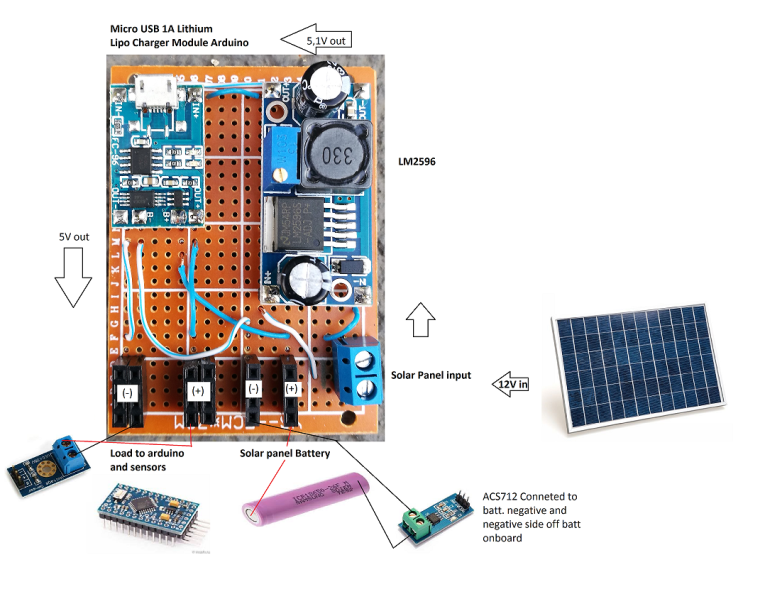
-
Hi. sorry for my late replay....
Here's the way i'm powering things up.
I don't have a solar charge since last summer we had a big fire on my island and all my arduino and sensors that were outside were all damage from the fire and hot temperatures. So to fiz this problem i'm using the LM2596 to reduce the 12V from the solar panels to 5.5V so that the lipo charger can work. Above the 5v this charger will get damage.Some data from this charger:
LED: Red = Charging, Green = Complete
Input Voltage: 4.5 to 5.5V
Battery Max Charge Voltage: 4.2V - charges a 1S Lithium Ion Polymer BatteryThis outputs a 4.2V on the load and batt connections.
My arduino and sensors are connected to the load pins from the lipo charger as you can see on the picture.
Thanks for your replay and help.@mrc-core The original circuit/sketch was designed for a 5v arduino and was measuring a 12v system . From your drawing it looks like you will be using a 3v arduino so at the very least you will need to change the voltage divider to give you a better resolution. As to the acs712 it is a 5v device so most likely will not even work on 3v so you may need to source some other device for current measurement. Again you would want a low current device if you are to have any chance of measuring the few milliamps you would be seeing. perhaps a google search for acs712 on 3v will produce a result.
-
@mrc-core The original circuit/sketch was designed for a 5v arduino and was measuring a 12v system . From your drawing it looks like you will be using a 3v arduino so at the very least you will need to change the voltage divider to give you a better resolution. As to the acs712 it is a 5v device so most likely will not even work on 3v so you may need to source some other device for current measurement. Again you would want a low current device if you are to have any chance of measuring the few milliamps you would be seeing. perhaps a google search for acs712 on 3v will produce a result.
@Boots33 I'm going to change the arduino mini for an arduino nano to have the 5V still have one in the house.
Acs712 have already buy 2 off them just in case if i have to go back to arduino mini.I was thinking on booting all my outside arduinos from this solar panel i have 2 more off them that i can connect.
-
@mrc-core The original circuit/sketch was designed for a 5v arduino and was measuring a 12v system . From your drawing it looks like you will be using a 3v arduino so at the very least you will need to change the voltage divider to give you a better resolution. As to the acs712 it is a 5v device so most likely will not even work on 3v so you may need to source some other device for current measurement. Again you would want a low current device if you are to have any chance of measuring the few milliamps you would be seeing. perhaps a google search for acs712 on 3v will produce a result.
-
@Boots33 I have change to an arduino nano but still get some strange values. I'm going to make some changes over this project and see again what ill get.
Thanks for all the help.
-
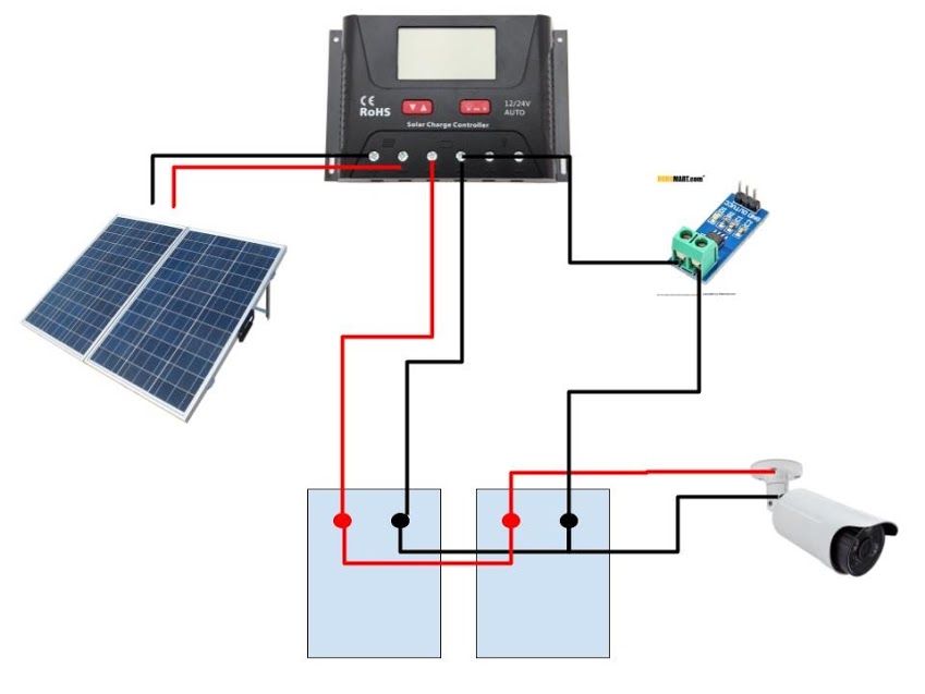
I just finished setting up this sensor to monitor my solar panels. The voltage sensors is reporting correct, but i'm not sure if the current sensor is right or wired correctly.
This is how it is currently wired.
Is this going to give me both charge and discharge?
Thanks!
-
I just finished setting up this sensor to monitor my solar panels. The voltage sensors is reporting correct, but i'm not sure if the current sensor is right or wired correctly.
This is how it is currently wired.
Is this going to give me both charge and discharge?
Thanks!
@unfadingpyro I can't see your wiring diagram.
-
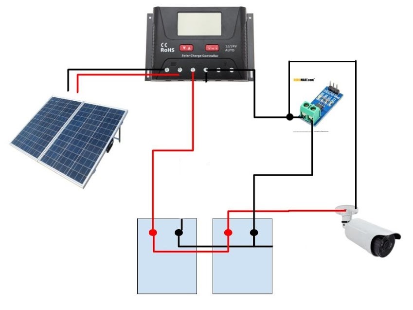
How about now?
-
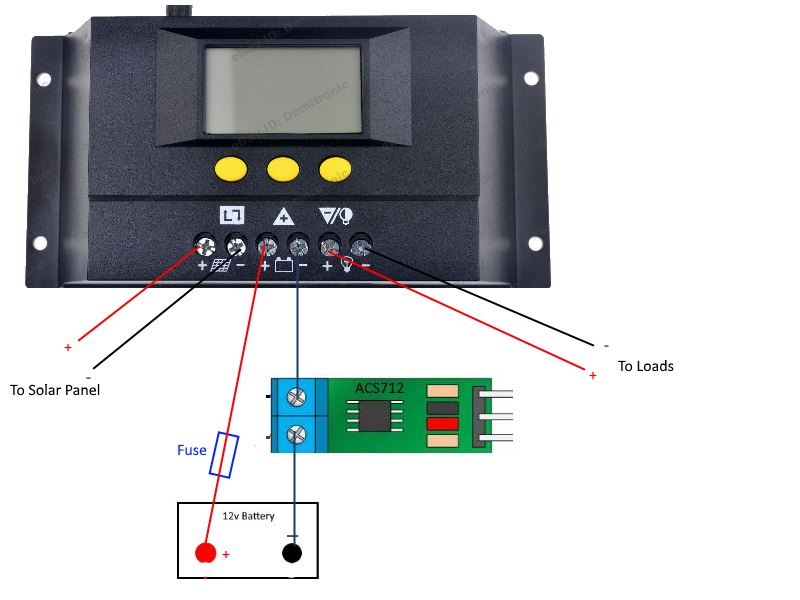
Yes i can see your wiring now and no you are not likely to get any sort of reading with that circuit. You have the 712 wired in parallel with the charge wire, it needs to be in series instead. The load needs to be connected to the same side that the charge wire is on. So a quick re-draw of your circuit would look like this.
Don't forget to add a fuse at the battery positive.
The original drawing from earlier in this thread would also be ok
-
Okay. I will rewire it this weekend. Thanks!
-
Get the sensor rewired yesterday and i am now getting the correct readings! Thanks again for the help.
-
Get the sensor rewired yesterday and i am now getting the correct readings! Thanks again for the help.
@unfadingpyro Great to hear you got it all working. Always a good feeling when a project comes together :)
-
Yes i can see your wiring now and no you are not likely to get any sort of reading with that circuit. You have the 712 wired in parallel with the charge wire, it needs to be in series instead. The load needs to be connected to the same side that the charge wire is on. So a quick re-draw of your circuit would look like this.
Don't forget to add a fuse at the battery positive.
The original drawing from earlier in this thread would also be ok
@Boots33 hi. Now, i'm working on this project for my final year project. I dont really used your overall project, i just used the concept which monitor the solar battery. I used your circuit diagram without using the transceiver and use my own code to run the project. In your opinion, is that make sense to you ?
-
@Boots33 hi. Now, i'm working on this project for my final year project. I dont really used your overall project, i just used the concept which monitor the solar battery. I used your circuit diagram without using the transceiver and use my own code to run the project. In your opinion, is that make sense to you ?
@nurul-amira Yes that should all work fine. That circuit has been running 24/7 for around 4 years now without any issues.
-
@nurul-amira Yes that should all work fine. That circuit has been running 24/7 for around 4 years now without any issues.
@Boots33 thank you for your time to reply me 😁.


Hello! It looks like you're interested in this conversation, but you don't have an account yet.
Getting fed up of having to scroll through the same posts each visit? When you register for an account, you'll always come back to exactly where you were before, and choose to be notified of new replies (either via email, or push notification). You'll also be able to save bookmarks and upvote posts to show your appreciation to other community members.
With your input, this post could be even better 💗
Register Login