Low power Distance Sensor - Hardware issues
-
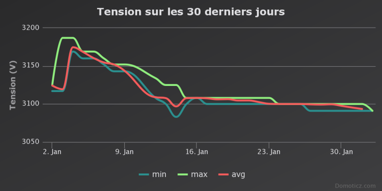
And here the latest battery graph displaying two things:
- The first phase with not that optimal battery consumption (until Jan, 14th)
- The second one with everything optimized (after Jan, 14th).
QQ.
-
Very nice project and thanks for sharing. I have a deer feeder in a corner of my yard, and it's always getting empty without me knowing. I'm planning on this exact same type of project to measure the level of corn in the feeder. Would love to see your final schematic and parts list (as it changed across the thread), but no worry if you don't have it as I'm sure I can figure it out.
Thanks again for sharing.
-
I think batteries and sonar distance sensor is not the best, it consumes too much power, since you must measure too often. A better solution if possible is to only get a interrupt with a switch when water tank is empty, then Arduino can sleep forever, or maybe you want to let it wake up once a day to provide a live puls. with a sonar you must check often and spend precious battery for distance measuring. Also there is no need of a DC-DC converter when using the switch, since the DC-DC converter also drains your batteries
Can you use something like this instead?
http://www.ebay.com/sch/sis.html?_nkw=New+Hot+Sale+Small+Liquid+Water+Level+Sensor+Horizontal+Float+Switch+WB&_id=301886450361&&_trksid=p2060353.m2749.l2658 -
Very nice project and thanks for sharing. I have a deer feeder in a corner of my yard, and it's always getting empty without me knowing. I'm planning on this exact same type of project to measure the level of corn in the feeder. Would love to see your final schematic and parts list (as it changed across the thread), but no worry if you don't have it as I'm sure I can figure it out.
Thanks again for sharing.
Thank you @stevebus. It's now live at its outdoor spot measuring the water in my well. It works perfectly :)
I'll post the photos and schemas once I get back from skiing ;)
-
I think batteries and sonar distance sensor is not the best, it consumes too much power, since you must measure too often. A better solution if possible is to only get a interrupt with a switch when water tank is empty, then Arduino can sleep forever, or maybe you want to let it wake up once a day to provide a live puls. with a sonar you must check often and spend precious battery for distance measuring. Also there is no need of a DC-DC converter when using the switch, since the DC-DC converter also drains your batteries
Can you use something like this instead?
http://www.ebay.com/sch/sis.html?_nkw=New+Hot+Sale+Small+Liquid+Water+Level+Sensor+Horizontal+Float+Switch+WB&_id=301886450361&&_trksid=p2060353.m2749.l2658@bjacobse , I do understand your concern ! That was my challenge for the past months. But the combination of digital output to trigger on/off the sensor, low update frequency (15 minutes) and a low power ultrasonic sensor makes it possible (ser posts above).
Qq.
-
Hello @qqlapraline
i want to build exactly this sensor like you do.
Can you help me with a wiring schema and a parts list?Thank you so much!
-
Here is the schematics (freshly made for you :))
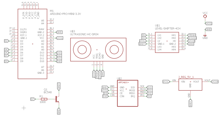
And here the part list:
- Arduino pro mini (3.3v with BOD disabled) or Sensebender Micro
- Ultrasonic sensor: ME007-ULS (available here)
- NRF24L01+ (I use the PA - LNA version for long range communication)
- NPN Transistor: BC548 (the B version if prefered)
- Base resistor: 1k
- 3.3V Step-up Voltage regulator: NCP1402 (available here)
- Logic Level Converter (available here): it says 3.3/5 but actually it's any to any voltage.
- Waterproof case (available here)
And finally here is my code (not cleaned, sorry).
0_1496348693347_DistanceSensebenderMicro.ino
And the Eagle SCH
0_1496348714531_Low power Distance Sensor.schAnd now, I realize that it may have been wise to upload that to openhardware.io :)
Regards,
QQ.
-
Thank you very much!
-
Here is the schematics (freshly made for you :))
And here the part list:
- Arduino pro mini (3.3v with BOD disabled) or Sensebender Micro
- Ultrasonic sensor: ME007-ULS (available here)
- NRF24L01+ (I use the PA - LNA version for long range communication)
- NPN Transistor: BC548 (the B version if prefered)
- Base resistor: 1k
- 3.3V Step-up Voltage regulator: NCP1402 (available here)
- Logic Level Converter (available here): it says 3.3/5 but actually it's any to any voltage.
- Waterproof case (available here)
And finally here is my code (not cleaned, sorry).
0_1496348693347_DistanceSensebenderMicro.ino
And the Eagle SCH
0_1496348714531_Low power Distance Sensor.schAnd now, I realize that it may have been wise to upload that to openhardware.io :)
Regards,
QQ.
-
@qqlapraline would you mind reupload your sketch?
-
Does it work fine ?
In case, you need it, here it goes again :)
0_1504557254355_DistanceSensebenderMicro.ino
Beware, it uses a former version of the MySensors library.QQ.
-
Does it work fine ?
In case, you need it, here it goes again :)
0_1504557254355_DistanceSensebenderMicro.ino
Beware, it uses a former version of the MySensors library.QQ.
@qqlapraline thanks! It works fine, thanks again!
-
I tried this with a similar setup but RFM95 for LoRaWan and without the transistor as I'm testing it directly on USB.
A pololu 5V stepup regulator does not even work directly on VCC - if I connect the HC-SR04, voltage drops from 5V
to 1.2V after the regulator.I then tried a different regulator from aliexpress, this setup works with the regulator on VCC, but if I try to control it through a
Pin, Voltage also drops and does not even power the regulator (it has a LED) :( -
From my experience, the transistor (or mosfet) is key to allow enough current to the DC-DC booster. Otherwise, it will not provide the appropriate voltage because max current getting out of a digital pin from Arduino is around 40 mA.
QQ.
-
I have a working setup now, however, it seems that I lose current through the trigger pin.
If I disconnect it, it drops.@qqlapraline what I don't get is: Do you really have GND on the high side of the LVL converter connected to GND as in your schematic?
Since the GND sides on the converter are connected, this closes the loop for the regulator, thus it would be turned on all the time?
Same for the HC-SR04Thanks!
@chbla well, yes. As the level adapter AND the booster are triggered only when needed (during the measure time), I don't see where it closes the loop.
By maybe I misunderstand something. Where do you loose some current ? The trigger pin from the HC-SR04 ?QQ.
-
What I mean is, those should be connected to GNDT not GND as in your diagram - right?
GND is permanent ground.I noticed I'm losing current through the trigger pin, the cause is apparently that if disconnected, the system is only on VCC.
Since the trigger bin is set to LOW in my previous sketch, it loses current there.But I found out that if I set the trigger pin to HIGH before sleeping, it's fine. My sketch uses 78ua while sleeping. Using a MOSFET at the moment
to switch. -
What I mean is, those should be connected to GNDT not GND as in your diagram - right?
GND is permanent ground.I noticed I'm losing current through the trigger pin, the cause is apparently that if disconnected, the system is only on VCC.
Since the trigger bin is set to LOW in my previous sketch, it loses current there.But I found out that if I set the trigger pin to HIGH before sleeping, it's fine. My sketch uses 78ua while sleeping. Using a MOSFET at the moment
to switch.@chbla, you are right. As mentionned on the schema, it should be connected to GNDT (the triggered GND). And now I do understand your point.
-
@chbla, you are right. As mentionned on the schema, it should be connected to GNDT (the triggered GND). And now I do understand your point.
@qqlapraline good to hear! :) Thanks for the confirmation
-
I need help :( - I have soldered the whole thing to a prototyping board, and now the Pro Mini keeps resetting.
Does anyone see a problem in the following schematic? (sorry for the drawing, I'm a bit limited here).
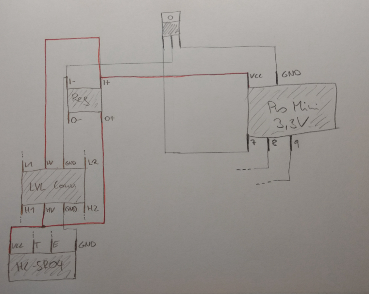
As mentioned I'm using a MOSFET, switched on/off via Pin 7.
Mosfet: https://de.aliexpress.com/item/10PCS-IRLB8721-TO220-IRLB8721PBF-TO-220-free-shipping/32714364118.html?spm=a2g0s.9042311.0.0.FjZdIJ
Vreg: https://de.aliexpress.com/item/2pcs-DC-DC-Power-Supply-Converter-Step-Up-Boost-Module-1A-3V-to-5V/32598574742.html?spm=a2g0s.9042311.0.0.IFPbYZ
Lvl Converter: https://de.aliexpress.com/item/Free-shipping-1pcs-4-channel-IIC-I2C-Logic-Level-Converter-Bi-Directional-Module-5V-to-3/32670479389.html?spm=a2g0s.9042311.0.0.OAwsE9It was working fine on the breadboard, but I have verified all the connections.
Right now it seems to reset all the time (2nd LED blinking on the arduino).
The regulator switches on and off with 1hz, the voltage between I+ and I- changes between 1.0V and 2.4V
If I connect GND to the regulator directly, bridging the Mosfet, it works.Any idea?