💬 Battery Powered Sensors
-
Search the forum. Booster VS not booster - its always a tradeoff.
Some people go further and skip booster and lower BOD on the arduino instead.
I would say 1.9V is pretty good... I have had my longest temp sensor now since the beginning (Almost 3 years) and changed 2xAA once. If you are using sleep and measure once you will get away with a long lasting sensor. -
At 0.95V per cell, an alkaline battery has delivered about 99% of its total capacity. Look at a discharge curve like this:
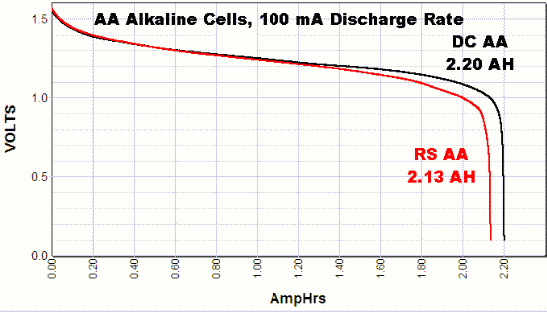
So if the booster has more than 1% overhead, using a booster to power nrf24 and atmega328 will give worse battery performance than running directly off 2 alkaline batteries.
-
Thats for the response guys. So tried connecting directly to the battery. I cut the trace on the pcb, then soldered a wire directly from the vIn to the positive leg of the 4.7u cap that leads to the radio. No joy though. Still same problem.
To the point about disabling bod, i have done that already, my issue with that setup though is that my dht22 seems to give inconsistent measurements when operating. It would give readings a degree apart every 5 minutes when the temperature would have remained a lot more stable. I assumed this to be due to the 2x batteries running at just a tad below 3v, while the dht22 is rated at 3.3v. Hence i thought the stepup would fix this problem.
@FatBeard - I use this setup, run the radio from the battery and arduino and dht22 from booster without problems. It should work. About the readings... as gohan said... the dht22 is known for... not that good quality
-
@FatBeard - I use this setup, run the radio from the battery and arduino and dht22 from booster without problems. It should work. About the readings... as gohan said... the dht22 is known for... not that good quality
I've actually ordered some bme280s which I'm waiting on, I think they will work down to low voltages too. So hopefully that will sort this issue by not needing the step up.
I would like to still to be able to figure out this problem though. I tried removing the dht22 completely to see if it was contributing to the problem, no luck. I've tried various capacitors over the ground and vout to no avail.
How would I go about analysing noise on the circuit?
-
@FatBeard - I use this setup, run the radio from the battery and arduino and dht22 from booster without problems. It should work. About the readings... as gohan said... the dht22 is known for... not that good quality
-
@sundberg84 I'll also take a look at your pcb. I was trying to achieve a pcb like that. A generic one to use with various sensors. I Was hoping to do it myself for the sake of learning. But I may have change tact.
@FatBeard - I would start by changing the Nrf24l01+ - there are some really bad ones out there.
Second I would rewire everyhing from/to the radio. After that I would rewire everything else and maybe change the arduino. As you said, removing all sensors and try debug in "bare minimun" (Power, Arudino and Radio) is a good idea. You can create a fake motion sensor sketch for example sending 1/0 with a 10 sec delay in between just to test the setup (without sensor attached). -
I'm using an approach read some thread bottom. Direct 2XAA to the Atmega barebone @8Mhz with BOD disabled and step up (not very efficient) to port the voltage of the batteries to a 3.3v for the DHT22. I'm reading the voltage with "secret voltmeter" example posted (https://provideyourown.com/2012/secret-arduino-voltmeter-measure-battery-voltage/ )
The Atmega sleep for 10 minutes, take reading and if different sends to the gateway (as your sketches). I want shutdown the booster, as it is not very efficient. I did have a debate on arduino forum: https://forum.arduino.cc/index.php?topic=488315.0
Basically, a part that I don't absolutely "cut the ground" with a NPN, otherwise I could have issues with different potential grounds etc etc, I don't know anymore if my design is secure and can works.
For all friday, saturday and sunday my node was power on without issues, but I don't want my house burning for a short circuit from batteries...
This is base fritzing draw:

And this is the real pictures of node:

And final this is the not-so-efficient booster: https://www.amazon.it/gp/product/B06XHJCHX6/ref=oh_aui_detailpage_o00_s00?ie=UTF8&psc=1 and regulated exit to 3.3v.
(Voltage goes down from friday to today from 2.74 to 2.63).
Am I wrong with my connections? Thank you to all....
-
I'm using an approach read some thread bottom. Direct 2XAA to the Atmega barebone @8Mhz with BOD disabled and step up (not very efficient) to port the voltage of the batteries to a 3.3v for the DHT22. I'm reading the voltage with "secret voltmeter" example posted (https://provideyourown.com/2012/secret-arduino-voltmeter-measure-battery-voltage/ )
The Atmega sleep for 10 minutes, take reading and if different sends to the gateway (as your sketches). I want shutdown the booster, as it is not very efficient. I did have a debate on arduino forum: https://forum.arduino.cc/index.php?topic=488315.0
Basically, a part that I don't absolutely "cut the ground" with a NPN, otherwise I could have issues with different potential grounds etc etc, I don't know anymore if my design is secure and can works.
For all friday, saturday and sunday my node was power on without issues, but I don't want my house burning for a short circuit from batteries...
This is base fritzing draw:
And this is the real pictures of node:
And final this is the not-so-efficient booster: https://www.amazon.it/gp/product/B06XHJCHX6/ref=oh_aui_detailpage_o00_s00?ie=UTF8&psc=1 and regulated exit to 3.3v.
(Voltage goes down from friday to today from 2.74 to 2.63).
Am I wrong with my connections? Thank you to all....
@sineverba I gave up trying to cross connect power controls directly and went for bistable telecoms relays, 100mW fire 30ms max latched stay open until you reverse signals from + & - pins. Works a treat, powered only for duration of latch....pity the sensor it controlled was shit, but hey ho....small steps
-
@sineverba I gave up trying to cross connect power controls directly and went for bistable telecoms relays, 100mW fire 30ms max latched stay open until you reverse signals from + & - pins. Works a treat, powered only for duration of latch....pity the sensor it controlled was shit, but hey ho....small steps
A bistable could cost more than entire node :D
But it could be an idea... instead of NPN. But remain my doubt.... for the moment, with node powered in this mode..... Am I in danger of burn battery / node / house? :(
-
If I were you I'd go for an I2C sensor that could also work at low voltage, this way you could also power the sensor via a digital pin and turn it off before entering the sleep function to save extra power.
-
A bistable could cost more than entire node :D
But it could be an idea... instead of NPN. But remain my doubt.... for the moment, with node powered in this mode..... Am I in danger of burn battery / node / house? :(
@sineverba I think the small latching Axicom 3v signal relay I used was around 2 euro, but they were sold in packs of 10, so expensive if no use for the other 9 :) The objective was low current low voltage short power duration, I found that the enable pin for the booster used more power when system was sleeping... switching the 5v booster by relay ensured no current leakage, 2 pins from the Arduino to control it, 30mA for 30ms to open, same to close it, as and when required to power the 5v ultrasonic... Arduino had it's own battery pack and booster but spends most of it's time in deep sleep so power consumption is peanuts.
-
@sineverba I think the small latching Axicom 3v signal relay I used was around 2 euro, but they were sold in packs of 10, so expensive if no use for the other 9 :) The objective was low current low voltage short power duration, I found that the enable pin for the booster used more power when system was sleeping... switching the 5v booster by relay ensured no current leakage, 2 pins from the Arduino to control it, 30mA for 30ms to open, same to close it, as and when required to power the 5v ultrasonic... Arduino had it's own battery pack and booster but spends most of it's time in deep sleep so power consumption is peanuts.
@zboblamont
Do you want post your schema // picture of your node? Thank you in advance :) -
@zboblamont
Do you want post your schema // picture of your node? Thank you in advance :)@sineverba None are finished, as waiting on the replacement ultrasonic to arrive. I posted photos of the original booster and JSN board at https://forum.mysensors.org/topic/4810/distance-sensor/43
when seeking opinions on potential noise issues. The tiny relay is also shown there.
The external nodes will all be Whisper Nodes (essentially a customised pro-mini), 2 have RTCs on board to take ultrasonic readings on two tanks, the rest respond to events. -
Atmega on breadboard, 8MHZ, no Xtal, BOD disabled.
I have a question and an issue.
This is exactly the breadboard (missing only the NRF, connected direct to the battery and not to the stepup and NRF has the 4.7mF capacitor and works very well on every other node).

This is my sketch > https://pastebin.com/raw/6Kxm238q
-
Can I remove one of the two 104 capacitors? Or I need both? Atmega feeded directly from battery, I remember.
-
With this setup, the node *doesn't trasmit and if I connect the serial (via FTDI232) Atmega floods it with strange characters and doesn't stop (I did try all the bauds, but default is 115200). The leds on FTDI232 blinks continuosly, 1 blink 1 strange chars printed on monitor serial.
2a) If I remove totally the ground between rails or remove totally the booster (so, for breviti, I don't give anymore power to the DHT22) the node trasmits very well (of course only the voltage) and serial works
2b) If I feed the node with 3.3v (e.g. from the FTDI232) the node transmits and serial is all ok.
At the end, seems that DHT 22 (rated for max 6V) doesn't want the 4.92V OR Atmega crash with this voltage.
PS I have the stepup to 5V 'case I did wrong the order..... :)
Thank you to all!
-
-
Atmega on breadboard, 8MHZ, no Xtal, BOD disabled.
I have a question and an issue.
This is exactly the breadboard (missing only the NRF, connected direct to the battery and not to the stepup and NRF has the 4.7mF capacitor and works very well on every other node).
This is my sketch > https://pastebin.com/raw/6Kxm238q
-
Can I remove one of the two 104 capacitors? Or I need both? Atmega feeded directly from battery, I remember.
-
With this setup, the node *doesn't trasmit and if I connect the serial (via FTDI232) Atmega floods it with strange characters and doesn't stop (I did try all the bauds, but default is 115200). The leds on FTDI232 blinks continuosly, 1 blink 1 strange chars printed on monitor serial.
2a) If I remove totally the ground between rails or remove totally the booster (so, for breviti, I don't give anymore power to the DHT22) the node trasmits very well (of course only the voltage) and serial works
2b) If I feed the node with 3.3v (e.g. from the FTDI232) the node transmits and serial is all ok.
At the end, seems that DHT 22 (rated for max 6V) doesn't want the 4.92V OR Atmega crash with this voltage.
PS I have the stepup to 5V 'case I did wrong the order..... :)
Thank you to all!
@sineverba your wiring looks quite odd. Especially compared to https://learn.adafruit.com/dht-humidity-sensing-on-raspberry-pi-with-gdocs-logging/overview
Where did you find the wiring guide? -
-
@sineverba your wiring looks quite odd. Especially compared to https://learn.adafruit.com/dht-humidity-sensing-on-raspberry-pi-with-gdocs-logging/overview
Where did you find the wiring guide?@mfalkvidd do u mean the DHT? I can assire you that resistor is between data and VCC ;-) maybe semms strange for need of arrangement on frtzing....... in effect at 3,3 it works and it works in another noce (at 3,3) i would understand because at 5v it doesnt works and serial is flooded ...... I could also post a picture of real breadboard :-)
Thank you!