💬 Building a Raspberry Pi Gateway
-
@marceloaqno
Ok I can you that file, but where is the best place to set Power Level and channel ?@gohan There isn't exactly the best place to set things, it really depends on your preferences.
-
-
@hawk_2050 same for you guys who helped, thank you for all the feedback.
@jerseyguy1996 I don't see anything wrong with your config.Try to add a small delay() after the first send() and before the sendBattery().
@annegerben This looks like a wire problem. I updated the guide, check the wire section again.
@marceloaqno I am trying to get a Pi 3 working with MySensors 2.1.1 and nrf24l01 and using your updated wire guide, but all I get as output is the following:
mysgw: Starting gateway...
mysgw: Protocol version - 2.1.1
mysgw: MCO:BGN:INIT GW,CP=RNNG--Q,VER=2.1.1
mysgw: TSF:LRT:OK
mysgw: TSM:INIT
mysgw: TSF:WUR:MS=0
mysgw: !TSM:INIT:TSP FAIL
mysgw: TSM:FAIL:CNT=1
mysgw: TSM:FAIL:PDT
[The output repeats itself, increasing the CNT every time, while at the same time one of the cores on the Pi 3 is running at full CPU utilization.]By reading earlier comments I assume this is a wiring problem. One possible cause is inconsistency between
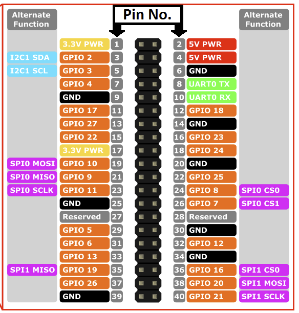
and
where the first picture indicates that pin 24 and pin 26 should be used, while the second indicates pins 22 and 24 should be used. However, I have tried both options but I still get the same output (I used different nrf24's for the different setups, in case the nrf24 got burned from the first setup).
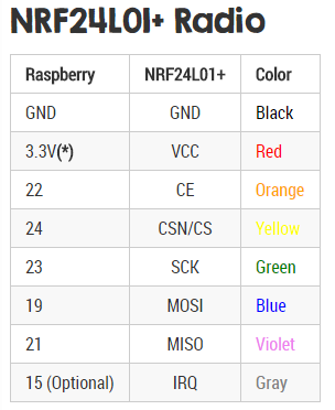
I have VCC from nrf24 connected to pin 17 on the Pi 3 and GND connect to pin 25.
Any suggestions on what to try next?
[The Pi 3 is running Raspbian with Pixel. For information, I already have a running Arduino with MySensors MQTT GW and a simple node with MySensors and DHT22. From this I know that by nrf24 chips works when being fed with 3.3V.] -
I have connected my nrf24 like the secon table you posted and it is working but I am using an "adapter" for nrf24 with a socket and has voltage regulator + capacitors, so if you don't have any cap on the radio module, I'd suggest you put one on (try from a 4.7 uF up to 47 and see if anything changes)
-
After updating domoticz to beta version I finally have the MQTT working with controller and I can see the sensor node seding in data: my question now is how to I debug the gateway if it is running as a service on the RPI without messing things up?
@gohan said in 💬 Building a Raspberry Pi Gateway:
After updating domoticz to beta version I finally have the MQTT working with controller and I can see the sensor node seding in data: my question now is how to I debug the gateway if it is running as a service on the RPI without messing things up?
I have my gateway on a headless pi 3, no monitor, GUI or keyboard. (I don't care for the nest of wires connection to the pi.) I also use MQTT which is very reliable.
An easy way to see the full MQTT traffic is to not start (or kill if it starts on boot) the MQTT server in the background, and start it in the console you can monitor. This won't impact Domotics one bit. In my case I do this by invoking "mosquitto -d" in the terminal
A simple way to monitor MQTT once its up and running is to look at the Domotics Log on the Setup menu.
Another way to watch it is to, in a terminal window such as running ssh from your computer, use MQTT "sub" in your terminal to see the MQTT traffic both ways to and from Domotics. If this isn't familiar, you need to learn it, (read the MQTT docs) and it's quite simple. Example might be "ssh pi@rpi.local" or "ssh <IP address>" from a computer on the local network, assuming the user is named pi and the pi is named "rpi"
Your MQTT topic must match what is in the sensor node sketch, the gateway sketch, and the domotics MQTT config. In my case I use "mosquitto_sub -d -v -t domoticz" and everything starts showing in real time in the terminal window.
MQTT is a bit more fiddly to set up but it's nice that different environments can push sensor data into the same MQTT server, in my case MySensors and ESP Easy.
Tim
-
@marceloaqno I am trying to get a Pi 3 working with MySensors 2.1.1 and nrf24l01 and using your updated wire guide, but all I get as output is the following:
mysgw: Starting gateway...
mysgw: Protocol version - 2.1.1
mysgw: MCO:BGN:INIT GW,CP=RNNG--Q,VER=2.1.1
mysgw: TSF:LRT:OK
mysgw: TSM:INIT
mysgw: TSF:WUR:MS=0
mysgw: !TSM:INIT:TSP FAIL
mysgw: TSM:FAIL:CNT=1
mysgw: TSM:FAIL:PDT
[The output repeats itself, increasing the CNT every time, while at the same time one of the cores on the Pi 3 is running at full CPU utilization.]By reading earlier comments I assume this is a wiring problem. One possible cause is inconsistency between
and
where the first picture indicates that pin 24 and pin 26 should be used, while the second indicates pins 22 and 24 should be used. However, I have tried both options but I still get the same output (I used different nrf24's for the different setups, in case the nrf24 got burned from the first setup).
I have VCC from nrf24 connected to pin 17 on the Pi 3 and GND connect to pin 25.
Any suggestions on what to try next?
[The Pi 3 is running Raspbian with Pixel. For information, I already have a running Arduino with MySensors MQTT GW and a simple node with MySensors and DHT22. From this I know that by nrf24 chips works when being fed with 3.3V.]@marlin said in 💬 Building a Raspberry Pi Gateway:
where the first picture indicates that pin 24 and pin 26 should be used, while the second indicates pins 22 and 24 should be used.
Be careful because the wiring page shows two pinout diagrams, one for the Pi 1, another for the Pi 2&3, but which is which is not inside the graphic itself. Please don't ask how I know. ;-)
Tim
-
@gohan said in 💬 Building a Raspberry Pi Gateway:
After updating domoticz to beta version I finally have the MQTT working with controller and I can see the sensor node seding in data: my question now is how to I debug the gateway if it is running as a service on the RPI without messing things up?
I have my gateway on a headless pi 3, no monitor, GUI or keyboard. (I don't care for the nest of wires connection to the pi.) I also use MQTT which is very reliable.
An easy way to see the full MQTT traffic is to not start (or kill if it starts on boot) the MQTT server in the background, and start it in the console you can monitor. This won't impact Domotics one bit. In my case I do this by invoking "mosquitto -d" in the terminal
A simple way to monitor MQTT once its up and running is to look at the Domotics Log on the Setup menu.
Another way to watch it is to, in a terminal window such as running ssh from your computer, use MQTT "sub" in your terminal to see the MQTT traffic both ways to and from Domotics. If this isn't familiar, you need to learn it, (read the MQTT docs) and it's quite simple. Example might be "ssh pi@rpi.local" or "ssh <IP address>" from a computer on the local network, assuming the user is named pi and the pi is named "rpi"
Your MQTT topic must match what is in the sensor node sketch, the gateway sketch, and the domotics MQTT config. In my case I use "mosquitto_sub -d -v -t domoticz" and everything starts showing in real time in the terminal window.
MQTT is a bit more fiddly to set up but it's nice that different environments can push sensor data into the same MQTT server, in my case MySensors and ESP Easy.
Tim
@Grubstake
I am using mqtt fx from pc and subscribing to topic # so I get the full traffic of what is going on, but I haven't had time lately to compare if you get same log details as the myscontroller connected to ethernet gateway or starting the gateway on rpi with debug flag -
@marceloaqno I am trying to get a Pi 3 working with MySensors 2.1.1 and nrf24l01 and using your updated wire guide, but all I get as output is the following:
mysgw: Starting gateway...
mysgw: Protocol version - 2.1.1
mysgw: MCO:BGN:INIT GW,CP=RNNG--Q,VER=2.1.1
mysgw: TSF:LRT:OK
mysgw: TSM:INIT
mysgw: TSF:WUR:MS=0
mysgw: !TSM:INIT:TSP FAIL
mysgw: TSM:FAIL:CNT=1
mysgw: TSM:FAIL:PDT
[The output repeats itself, increasing the CNT every time, while at the same time one of the cores on the Pi 3 is running at full CPU utilization.]By reading earlier comments I assume this is a wiring problem. One possible cause is inconsistency between
and
where the first picture indicates that pin 24 and pin 26 should be used, while the second indicates pins 22 and 24 should be used. However, I have tried both options but I still get the same output (I used different nrf24's for the different setups, in case the nrf24 got burned from the first setup).
I have VCC from nrf24 connected to pin 17 on the Pi 3 and GND connect to pin 25.
Any suggestions on what to try next?
[The Pi 3 is running Raspbian with Pixel. For information, I already have a running Arduino with MySensors MQTT GW and a simple node with MySensors and DHT22. From this I know that by nrf24 chips works when being fed with 3.3V.]@marlin Got the same issue, Did you solve yours and if so how?
-
@marlin Got the same issue, Did you solve yours and if so how?
@keldandorin Yes. See the response by @gohan. I used a "adapter" with a voltage regulator on it etc. Though, at the moment I don't recall the model number.
-
@marlin Got the same issue, Did you solve yours and if so how?
@keldandorin just add a capacitor between vcc and gnd on the radio module as I suggested above.
-
I am trying to connect NRF24L01+ and Raspberry Pi 2 (Model B+). I am confuse about pin 22/24 too. In the diagram it shows "SPI0 CS0" and "SPI0 CS1" but these two pins aren't exist in NRF24L01+. How should I connect the pin? I connect Pi2 pin 24 to CS and Pi2 pin 26 to CE (Not sure it is correct)? Here is the message from
mysgw:[root@alarmpi bin]# ./mysgw -d mysgw: Starting gateway... mysgw: Protocol version - 2.1.1 mysgw: MCO:BGN:INIT GW,CP=RNNG---,VER=2.1.1 mysgw: TSM:INIT mysgw: TSF:WUR:MS=0 mysgw: !TSM:INIT:TSP FAIL mysgw: TSM:FAIL:CNT=1 mysgw: TSM:FAIL:PDT mysgw: TSM:FAIL:RE-INIT mysgw: TSM:INIT mysgw: !TSM:INIT:TSP FAIL mysgw: TSM:FAIL:CNT=2 mysgw: TSM:FAIL:PDT mysgw: TSM:FAIL:RE-INIT mysgw: TSM:INIT mysgw: !TSM:INIT:TSP FAIL mysgw: TSM:FAIL:CNT=3 mysgw: TSM:FAIL:PDT -
I am trying to connect NRF24L01+ and Raspberry Pi 2 (Model B+). I am confuse about pin 22/24 too. In the diagram it shows "SPI0 CS0" and "SPI0 CS1" but these two pins aren't exist in NRF24L01+. How should I connect the pin? I connect Pi2 pin 24 to CS and Pi2 pin 26 to CE (Not sure it is correct)? Here is the message from
mysgw:[root@alarmpi bin]# ./mysgw -d mysgw: Starting gateway... mysgw: Protocol version - 2.1.1 mysgw: MCO:BGN:INIT GW,CP=RNNG---,VER=2.1.1 mysgw: TSM:INIT mysgw: TSF:WUR:MS=0 mysgw: !TSM:INIT:TSP FAIL mysgw: TSM:FAIL:CNT=1 mysgw: TSM:FAIL:PDT mysgw: TSM:FAIL:RE-INIT mysgw: TSM:INIT mysgw: !TSM:INIT:TSP FAIL mysgw: TSM:FAIL:CNT=2 mysgw: TSM:FAIL:PDT mysgw: TSM:FAIL:RE-INIT mysgw: TSM:INIT mysgw: !TSM:INIT:TSP FAIL mysgw: TSM:FAIL:CNT=3 mysgw: TSM:FAIL:PDT@ccy Look at the chart below "NRF24L01+ Radio". That shows the PIN numbers on the Pi and the pin labels on the radio to interconnect. Pay no attention to the labels on the RPi generic pinout diagram except the PIN numbers. The RPi SPIO labels are not what you are looking for. And be sure to use the chart for the correct RPi model.
-
@Grubstake: Thanks. I have tried to follow "NRF24L01+ Radio" pin out connection. I have double / triple check my wiring is correct. But I still get the same fail message in mysgw debug mode:
[root@alarmpi bin]# ./mysgw -d mysgw: Starting gateway... mysgw: Protocol version - 2.1.1 mysgw: MCO:BGN:INIT GW,CP=RNNG---,VER=2.1.1 mysgw: TSM:INIT mysgw: TSF:WUR:MS=0 mysgw: !TSM:INIT:TSP FAIL mysgw: TSM:FAIL:CNT=1 mysgw: TSM:FAIL:PDT mysgw: TSM:FAIL:RE-INIT mysgw: TSM:INIT mysgw: !TSM:INIT:TSP FAIL mysgw: TSM:FAIL:CNT=2 mysgw: TSM:FAIL:PDT mysgw: TSM:FAIL:RE-INIT mysgw: TSM:INIT mysgw: !TSM:INIT:TSP FAIL mysgw: TSM:FAIL:CNT=3 mysgw: TSM:FAIL:PDT mysgw: Received SIGINTHere is my
/boot/config.txt:gpu_mem=64 initramfs initramfs-linux.img followkernel dtparam=spi=onand the spi dev:
# ls /dev/spidev0.*
/dev/spidev0.0  /dev/spidev0.1
I am using ArchLinuxARM:
# uname -a
Linux alarmpi 4.9.13-3-ARCH #1 SMP Fri Mar 3 18:45:16 MST 2017 armv7l GNU/Linux
I only wiring 7 pins (1-7) on
NRF24l01+.Raspberry Pi 2 hardware information:
# cat /proc/cpuinfo
processor       : 0
model name      : ARMv7 Processor rev 5 (v7l)
BogoMIPS        : 38.40
Features        : half thumb fastmult vfp edsp neon vfpv3 tls vfpv4 idiva idivt vfpd32 lpae evtstrm
CPU implementer : 0x41
CPU architecture: 7
CPU variant     : 0x0
CPU part        : 0xc07
CPU revision    : 5

processor       : 1
model name      : ARMv7 Processor rev 5 (v7l)
BogoMIPS        : 38.40
Features        : half thumb fastmult vfp edsp neon vfpv3 tls vfpv4 idiva idivt vfpd32 lpae evtstrm
CPU implementer : 0x41
CPU architecture: 7
CPU variant     : 0x0
CPU part        : 0xc07
CPU revision    : 5

processor       : 2
model name      : ARMv7 Processor rev 5 (v7l)
BogoMIPS        : 38.40
Features        : half thumb fastmult vfp edsp neon vfpv3 tls vfpv4 idiva idivt vfpd32 lpae evtstrm
CPU implementer : 0x41
CPU architecture: 7
CPU variant     : 0x0
CPU part        : 0xc07
CPU revision    : 5

processor       : 3
model name      : ARMv7 Processor rev 5 (v7l)
BogoMIPS        : 38.40
Features        : half thumb fastmult vfp edsp neon vfpv3 tls vfpv4 idiva idivt vfpd32 lpae evtstrm
CPU implementer : 0x41
CPU architecture: 7
CPU variant     : 0x0
CPU part        : 0xc07
CPU revision    : 5

Hardware        : BCM2835
Revision        : a21041
Serial          : 00000000475d18a4

# cat /sys/firmware/devicetree/base/model
Raspberry Pi 2 Model B Rev 1.1
Output from MySensors
configure:# ./configure [SECTION] Detecting target machine. ./configure: line 111: warning: command substitution: ignored null byte in input [OK] machine detected: SoC=unknown, Type=unknown, CPU=armv7l. [SECTION] Checking GPIO Sysfs. [OK] /sys/class/gpio/export found [SECTION] Detecting SPI driver. [OK] SPI driver detected:SPIDEV. [SECTION] Detecting init system. [OK] init system detected: systemd. [SECTION] Saving configuration. [SECTION] Cleaning previous builds. [OK] Finished.I finally find out my raspberry pi board isn't detected properly in
configure. I change thefunction detect_machine:function detect_machine { ... case $hardware in ... BCM2835) soc="BCM2835" if [[ $machine == "Raspberry"* ]]; then local rev=($(detect_rpi_revision)) if [[ $rev == "a02082" || $rev == "a22082" ]]; then tp="RPi3" else tp="Rpi2" fi fi ;; ...make
mysgwagain, and I get this finally:# ./mysgw -d mysgw: Starting gateway... mysgw: Protocol version - 2.1.1 mysgw: MCO:BGN:INIT GW,CP=RNNG---,VER=2.1.1 mysgw: TSF:LRT:OK mysgw: TSM:INIT mysgw: TSF:WUR:MS=0 mysgw: TSM:INIT:TSP OK mysgw: TSM:INIT:GW MODE mysgw: TSM:READY:ID=0,PAR=0,DIS=0 mysgw: MCO:REG:NOT NEEDED mysgw: Listening for connections on 0.0.0.0:5003 mysgw: MCO:BGN:STP mysgw: MCO:BGN:INIT OK,TSP=1 -
I can run
mysgw. But what can I use it for? I want to make it control my light with 2.4G RF. But I don't know what to do next. Please advice Thank you. -
@ccy
You need to provide some more details about your hw and general setup, what have you done so far, log messages, etc.