💬 Water Meter Pulse Sensor
-
I think i have fix my problem. I have been playing with the code and the sensor and notice that the power led and data led on the sensor were always on no mater the digital pin i was trying to use.
This also happened with the analog pin A0.
In one last attempt i decided to use the digital pin 3 with the resistor soldered on the board for sensors like dallas and dht11 or dht22.Now the first thing i had noticed was the data led was not on and now it only comes on when i passe a magnet under my sensor... it does not count any pulsecount if i passe the magnet over the sensor only under it.
Counted the times i had passed the magnet under the sensor and my gateway received te exact number 30 times = 0.030 volume and now the volume is stop at this number no more ghost encrease numbers.
Tomorrow morning i'm going to mount the sensor over the water meter to see if this finaly works.
The only problem i'm getting now is some NACK over the transmissions... like this:
6604747 TSF:MSG:SEND,1-1-0-0,s=1,c=1,t=25,pt=5,l=4,sg=0,ft=3,st=OK:30
volume:0.030
604794 !TSF:MSG:SEND,1-1-0-0,s=1,c=1,t=35,pt=7,l=5,sg=0,ft=0,st=NACK:0.030
pulsecount:30
634781 !TSF:MSG:SEND,1-1-0-0,s=1,c=1,t=25,pt=5,l=4,sg=0,ft=1,st=NACK:30
volume:0.030
634828 !TSF:MSG:SEND,1-1-0-0,s=1,c=1,t=35,pt=7,l=5,sg=0,ft=2,st=NACK:0.030 -
@mrc-core The NACK may be bad transmission. I typically connect a 5 cm piece of wire to the antenna of the send/receive module to increase the reception of data
@bart59 and @mfalkvidd Thanks for all the help. Today i toke the sensor to the water meter and for my luck my water meter is too old 1997 and no mater the position i put the hall sensor it just doesn't get any pulse at all :( at this time i really don't now what to use to get the data from my water meter...
I have already tried also the TCRT5000 and also does not work. Here's an image from my water meter
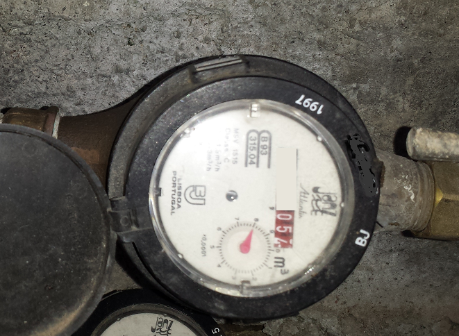
The TCRT5000 when i put over the glass the green led stays always on but when i remove it from the glass and point it to the black part of my meter the green led goes off the sensor is working ok but the glass from my meter does not help at all.
Any sugestions off other sensors i can try or use ?
-
@bart59 and @mfalkvidd Thanks for all the help. Today i toke the sensor to the water meter and for my luck my water meter is too old 1997 and no mater the position i put the hall sensor it just doesn't get any pulse at all :( at this time i really don't now what to use to get the data from my water meter...
I have already tried also the TCRT5000 and also does not work. Here's an image from my water meter
The TCRT5000 when i put over the glass the green led stays always on but when i remove it from the glass and point it to the black part of my meter the green led goes off the sensor is working ok but the glass from my meter does not help at all.
Any sugestions off other sensors i can try or use ?
@mrc-core You are right. This is the wrong type of water meter. I have been using 2 other brands watermeters: the Honeywell C7195x2001B (see http://ecc.emea.honeywell.com/downloads/EN2R9029.PDF) and the Caleffi series 316 (http://www.arbo.it/images/techsheets/316405.pdf). You local central heating installation guy may have them as they are used in boiler systems of central heating for the warm water supply. They are also sold on eBay. Both work more or less the same and can be operated on 5V. The number of pulses per liter are much higher (something like 500 pulses per liter), so they are more accurate. You will need to modify your code to work with this. Below the code of my sensor (which also measures multiple temperatures at the same Arduino chip):
/**
 * The MySensors Arduino library handles the wireless radio link and protocol
 * between your home built sensors/actuators and HA controller of choice.
 * The sensors forms a self healing radio network with optional repeaters. Each
 * repeater and gateway builds a routing tables in EEPROM which keeps track of the
 * network topology allowing messages to be routed to nodes.
 *
 * Created by Henrik Ekblad <henrik.ekblad@mysensors.org>
 * Copyright (C) 2013-2015 Sensnology AB
 * Full contributor list: https://github.com/mysensors/Arduino/graphs/contributors
 *
 * Documentation: http://www.mysensors.org
 * Support Forum: http://forum.mysensors.org
 *
 * This program is free software; you can redistribute it and/or
 * modify it under the terms of the GNU General Public License
 * version 2 as published by the Free Software Foundation.
 *
 * (c) 2017 Bart M - last edits: 15 May 2017
 *
 * Note: using timer0 to generate a second interrupt for our 1 ms counters. timer0 is still also  used for delay()
 *
 * Functions WTW Flow and Temperature
 *
 * WTW flow
 *  - Flow of shower cold water
 *  - Flow of boiler cold water entry
 *
 * Temperature
 * - Temperature of outgoing water (Dallas with cable)
 * - Temperature of shower head (Dallas)
 *
 * Flow meter using Honeywell C7195A2001B which has a hall sensor that pulses at 7 Hz per liter/min
 * we count only upgoing pulses, so in our case we get:
 *   7 pulses per second at 1 l/min
 *   420 pulses per liter
 *   420000 pulses per m3
 * Flow meter Caleffi 316 which has a hall sensor that pulses at 8.8 Hz per liter/min (according to specs)
 * In reality the frequency is about 30% lower in my case, so we have to correct this with a factor of 1.3.
 *   8.8 pulses per second at 1 l/min
 *   528 pulses per liter
 *   528000 pulses per m3
 *   528000/1.3 = 406154
 *
 * If we use 250 m3 per year we come to 105 x 10^6 pulses/year
 *`this is stored in an unsigned long that can hold 4295 x 10^6 -> volume overflow after 41 years
 *
 *****************************************************************************************************  */

// BOARD: PRO MINI 5V V/ 16Mhz ATMEGA328 16Mhz

// type of flow meter
#define CALEFFI
// #define HONEYWELL

// Enable debug prints to serial monitor
#define MY_DEBUG 1

// Enable and select radio type attached
#define MY_RADIO_NRF24
// No repeater

// node ID's
#define MY_NODE_ID 27             // start naming my own nodes at number (set in comments if you want automatic)
#define FLOW_ID 1                 // flow meter 1 (start here if more)
#define NFLOWS 2                  // number of flow meters
#define TEMP_ID 3                 // Temperature (start here if there are more linked)

#include <SPI.h>
#include <MySensors.h>
#include <DallasTemperature.h>
#include <OneWire.h>

// PIN connections where the flow meters are connected. We have 2 flow meters, so our array has 2 entries
uint8_t FlowPins[NFLOWS] = {2, 3};
#define TEMP_PIN 4                // temp sensor connected to pin4

#ifdef CALEFFI
// #define PULSE_FACTOR 528000        // Number of blinks per m3 of your meter Caleffi (from data sheet)
#define PULSE_FACTOR 406154        // Nummber of blinks per m3 of your meter Caleffi (measured in my installation)
#else
#define PULSE_FACTOR 420000        // Nummber of blinks per m3 of your meter Honeywell
#endif

// configs
#define MAXFLOWERROR 50             // maximum number of l/min that we accept

// delay times
#define CHECK_FREQUENCY 1000         // time in milliseconds between loop (where we check the sensor) - 1000ms
#define MIN_SEND_FREQ 10             // Minimum time between send (in multiplies of CHECK_FREQUENCY). We don't want to spam the gateway (10 seconds)
#define MIN_FLOW_SEND_FREQ 20        // Minimum time between send (in multiplies of CHECK_FREQUENCY). We don't want to spam the gateway (30 seconds)
#define MAX_SEND_FREQ 600            // Maximum time between send (in multiplies of CHECK_FREQUENCY). We need to show we are alive (600 sec/10 min)

// one wire config
#define ONE_WIRE_BUS TEMP_PIN
#define MAX_ATTACHED_DS18B20 8

// Motion message types
MyMessage volumeMsg(FLOW_ID,V_VOLUME);
MyMessage flowMsg(FLOW_ID,V_FLOW);
MyMessage lastCounterMsg(FLOW_ID,V_VAR1);
MyMessage tempmsg(TEMP_ID, V_TEMP);

OneWire oneWire(ONE_WIRE_BUS); // Setup a oneWire instance to communicate with any OneWire devices (not just Maxim/Dallas temperature ICs)
DallasTemperature sensors(&oneWire); // Pass the oneWire reference to Dallas Temperature.
float lastTemperature[MAX_ATTACHED_DS18B20];
volatile unsigned int numSensors = 0;

double ppl = ((double)PULSE_FACTOR / 1000.0);    // Pulses per liter
boolean pcReceived[NFLOWS];                      // received volume from prior reboot
double oldflow[NFLOWS];                          // keep prior flow (only send on change)
unsigned long oldflow_cnt[NFLOWS];               // only send when changed


// updated in ISR
volatile unsigned int mcnt = CHECK_FREQUENCY;   // decremented in ISR at 1000Hz. Cycles at one per second to update send counters
volatile unsigned int tempsendcnt[MAX_ATTACHED_DS18B20];
volatile unsigned int maxtempsendcnt[MAX_ATTACHED_DS18B20];
volatile unsigned int flowsendcnt[NFLOWS];
volatile unsigned int maxflowsendcnt[NFLOWS];
volatile bool flow_status[NFLOWS];              // status of flow (on or off cycle)
volatile unsigned long flow_cnt[NFLOWS];        // counter volume for each flow sensor
volatile unsigned int intervalcnt[NFLOWS];      // keep track of number of milliseconds since we had previous flow info

void before() {
  for (uint8_t i=0; i<NFLOWS; i++) {
    pinMode(FlowPins[i], INPUT);
  }
  // Startup up the OneWire library
  sensors.begin();
  for (uint8_t i=0; i<NFLOWS; i++) {
    oldflow[i] = 0;
    flow_status[i] = false;
    flow_cnt[i] = 0;
    oldflow_cnt[i] = 0;
    pcReceived[i] = false;
    flowsendcnt[i] = MIN_FLOW_SEND_FREQ;
    maxflowsendcnt[i] = MAX_SEND_FREQ;
    intervalcnt[i] = 0;
  }
  for (uint8_t i=0; i<MAX_ATTACHED_DS18B20; i++) {
     lastTemperature[i]=0;
     tempsendcnt[i] = 0;
     maxtempsendcnt[i] = MAX_SEND_FREQ;
  }
}

void setup() {
   Serial.println("setup()");
   // Timer0 is already used for millis() - we'll just interrupt somewhere
   // in the middle and call the TIMER0_COMPA_vect interrupt
   OCR0A = 0xAF;
   TIMSK0 |= _BV(OCIE0A);
   sensors.setWaitForConversion(true);
   // Fetch last known pulse count value from gw
   for (uint8_t i=0; i<NFLOWS; i++) {
     request(FLOW_ID+i, V_VAR1);
   }
}

void presentation()  {
  // Send the sketch version information to the gateway and Controller
  sendSketchInfo("WTW flow sensor", "1.2");

  // Register all sensors to gw (they will be created as child devices)
  numSensors = sensors.getDeviceCount();
  Serial.print("# temp sensors: ");
  Serial.println(numSensors);
  DeviceAddress add;
  for (uint8_t i=0; i<numSensors && i<MAX_ATTACHED_DS18B20; i++) {
     present(TEMP_ID+i, S_TEMP);
     Serial.print(i);
     Serial.print("=");
     sensors.getAddress(add, i);
     printAddress(add);
     Serial.println();
  }
  for (uint8_t i=0; i<NFLOWS; i++) {
    present(FLOW_ID+i, S_WATER);
  }
}

// function to print a device address of a Dallas temp sensor
void printAddress(DeviceAddress deviceAddress) {
  for (uint8_t i = 0; i < 8; i++) {
    // zero pad the address if necessary
    if (deviceAddress[i] < 16) Serial.print("0");
    Serial.print(deviceAddress[i], HEX);
  }
}


void loop() {
  // we come here every 1000 ms (defined in CHECK_FREQUENCY)

  // now handle temperature
  if (numSensors>0) {
    sensors.requestTemperatures();
    for (uint8_t i=0; i<numSensors && i<MAX_ATTACHED_DS18B20; i++) {
      // Fetch and round temperature to one decimal
      float temperature = static_cast<float>(static_cast<int> (sensors.getTempCByIndex(i) * 10.)) / 10.;

      // Only send data if temperature has changed and no error
      if (((lastTemperature[i] != temperature && tempsendcnt[i]==0) || maxtempsendcnt[i]==0) && temperature != -127.00 && temperature != 85.00) {
        // Send in the new temperature
        send(tempmsg.setSensor(TEMP_ID+i).set(temperature,1));
        // Save new temperature for next compare
        lastTemperature[i]=temperature;
        tempsendcnt[i] = MIN_SEND_FREQ;
        maxtempsendcnt[i] = MAX_SEND_FREQ;
      }
    }
    for (uint8_t i=0; i<NFLOWS; i++) {
       if ((flowsendcnt[i]==0 && (oldflow_cnt[i] != flow_cnt[i])) || (flowsendcnt[i]==0 && oldflow[i] != 0) || maxflowsendcnt[i]==0) {
          if (!pcReceived[i]) {   //Last Pulsecount not yet received from controller, request it again
             Serial.print("Re-request var1 for sensor ");
             Serial.println(FLOW_ID+i);
             request(FLOW_ID+i, V_VAR1);
             wait(2*CHECK_FREQUENCY); // wait at least 1000 ms for gateway (cannot be sleep or smartSleep)
             return;
          }
          flowsendcnt[i] = MIN_FLOW_SEND_FREQ;
          maxflowsendcnt[i] = MAX_SEND_FREQ;
          double volume = ((double)flow_cnt[i]/((double)PULSE_FACTOR));
          double flow = (((double) (flow_cnt[i]-oldflow_cnt[i])) * ((double) 60000.0 / ((double) intervalcnt[i]))) / ppl;  // flow in liter/min

          Serial.print("Flow meter:");
          Serial.println(FLOW_ID+i);
          Serial.print("pulsecount:");
          Serial.println(flow_cnt[i]);
          Serial.print("volume:");
          Serial.println(volume, 3);
          Serial.print("l/min:");
          Serial.println(flow);
          intervalcnt[i] = 0;
          oldflow[i] = flow;
          oldflow_cnt[i] = flow_cnt[i];
          send(lastCounterMsg.setSensor(FLOW_ID+i).set(flow_cnt[i]));     // Send  pulsecount value to gw in VAR1
          send(volumeMsg.setSensor(FLOW_ID+i).set(volume, 3));            // Send volume (set function 2nd argument is resolution)
          if (flow<MAXFLOWERROR) send(flowMsg.setSensor(FLOW_ID+i).set(flow, 2));                // Send flow value to gw
       }
    }
  }

  // Serial.print(end_loop-start_loop);
  wait(CHECK_FREQUENCY);
}

// Receive data from gateway
void receive(const MyMessage &message) {
  for (uint8_t i=0; i<NFLOWS; i++) {
     if (message.type==V_VAR1 && message.sensor==FLOW_ID+i) {
        unsigned long gwPulseCount=message.getULong();
        flow_cnt[i] += gwPulseCount;
        oldflow_cnt[i] += gwPulseCount;
        oldflow[i] = 0;
        Serial.print("Received last pulse count for ");
        Serial.print(FLOW_ID+i);
        Serial.print(" from gw:");
        Serial.println(gwPulseCount);
        pcReceived[i] = true;
     }
  }
}


// Interrupt on timer0 - called as part of timer0 - already running at 1ms intervals
SIGNAL(TIMER0_COMPA_vect) {
  if (mcnt>0) mcnt--;
  for (uint8_t i=0; i<NFLOWS; i++) {
     if (mcnt==0) {
        if (flowsendcnt[i]>0) flowsendcnt[i]--;
        if (maxflowsendcnt[i]>0) maxflowsendcnt[i]--;
     }
     intervalcnt[i]++;
     bool val = digitalRead(FlowPins[i]);
     if (val != flow_status[i]) {
        flow_status[i] = val;
        if (!val) flow_cnt[i]++;      // we increment counter on down flank
     }
  }
  if (mcnt==0) {
     mcnt = CHECK_FREQUENCY;
     for (uint8_t i=0; i<numSensors && i<MAX_ATTACHED_DS18B20; i++) {
        if (tempsendcnt[i]>0) tempsendcnt[i]--;
        if (maxtempsendcnt[i]>0) maxtempsendcnt[i]--;
     }
  }
}
Good luck
Bart
-
@bart59 and @mfalkvidd Thanks for all the help. Today i toke the sensor to the water meter and for my luck my water meter is too old 1997 and no mater the position i put the hall sensor it just doesn't get any pulse at all :( at this time i really don't now what to use to get the data from my water meter...
I have already tried also the TCRT5000 and also does not work. Here's an image from my water meter
The TCRT5000 when i put over the glass the green led stays always on but when i remove it from the glass and point it to the black part of my meter the green led goes off the sensor is working ok but the glass from my meter does not help at all.
Any sugestions off other sensors i can try or use ?
@mrc-core If I do a search for "B93 315.04 lisboa" I get MSV Janz company turn up, but I don't understand Portugese. It is probably a magnetic drive even at 1997 fabrication, but perhaps some searching will yield clues or contact the manufacturer?
-
@mrc-core If I do a search for "B93 315.04 lisboa" I get MSV Janz company turn up, but I don't understand Portugese. It is probably a magnetic drive even at 1997 fabrication, but perhaps some searching will yield clues or contact the manufacturer?
@zboblamont I have already read that pdf there they say this:
"The design of the Magnetic Transmission reduces the number of components
Operating in the water, increasing the reliability of the meter."They also say this in the pdf:
"Any of these models can be supplied ready to receive the
Pulse transmission (see tele-count catalog). Ex .: MSV 1520t"In this last information i made a search for MSV 1520t were i found again another pdf that talks about my water meter.
Here's the link: http://resopre.pt/conteudo.php?fam=CONTADORES,CONT_DOMESTICOS&pag=AGUA_RESOPRE.PT&detail=693You can see 5 water meters on that link all off them say's Magnetic Transmission "Transmissão magnética" but has you can see none off them look like mine. Has i can understand mine is the more basic off them all i do belive that i have the first generation off this water meters.
I have done one last test yesterday leaving a water tap open and passed the hall sensor all over the water meter from side to side and top to bottom and never got any impulse digital led light turning on.
The led did turned on when i put my finger in the top off the sensor or in cables near the pins of the sensor. -
@zboblamont I have already read that pdf there they say this:
"The design of the Magnetic Transmission reduces the number of components
Operating in the water, increasing the reliability of the meter."They also say this in the pdf:
"Any of these models can be supplied ready to receive the
Pulse transmission (see tele-count catalog). Ex .: MSV 1520t"In this last information i made a search for MSV 1520t were i found again another pdf that talks about my water meter.
Here's the link: http://resopre.pt/conteudo.php?fam=CONTADORES,CONT_DOMESTICOS&pag=AGUA_RESOPRE.PT&detail=693You can see 5 water meters on that link all off them say's Magnetic Transmission "Transmissão magnética" but has you can see none off them look like mine. Has i can understand mine is the more basic off them all i do belive that i have the first generation off this water meters.
I have done one last test yesterday leaving a water tap open and passed the hall sensor all over the water meter from side to side and top to bottom and never got any impulse digital led light turning on.
The led did turned on when i put my finger in the top off the sensor or in cables near the pins of the sensor.@mrc-core Well, I did suggest contacting the manufacturer with the information on your meter, they are better able to advise or may even sell a sensor head to retrofit. Usually these manufacturers are very helpful, and at least you speak the language.
I know that some manufacturers insist on factory building the sensor arrangement inside the meter (Zenner?) but you may be lucky.
The magnetic drive is more to avoid mechanical connection between the metering section and the water flow, so no axle or sealing ring to leak !
I have a plastic Elster, it has the same magnetic coupling as yours, but I was unable to sense any changing magnetic field when I checked it, but I had already ordered the specific read head for it so was not unduly concerned, and it should arrive in next few days. This sensor pulses when a small metal arc on the small dial passes beneath the sensor every 1 litre. It was around 30 euro from memory, so not a mad price. -
Hello,
i have got water meter with pulse output. So I have just arduino and RFM69W. Sleep mode false/true works well with standard bootloader. Optiboot with sleep mode false works also well. But I would like to run it on battery optiboot with true sleep mode which doens work correctly. Sensor doesnt receiceve last pulse count from gw.
Any idea how to fix it?0 MCO:BGN:INIT NODE,CP=RRNNA--,VER=2.1.1
4 TSM:INIT
4 TSF:WUR:MS=0
8 TSM:INIT:TSP OK
10 TSM:INIT:STATID=3
12 TSF:SID:OK,ID=3
14 TSM:FPAR
145 TSF:MSG:SEND,3-3-255-255,s=255,c=3,t=7,pt=0,l=0,sg=0,ft=0,st=OK:
743 TSF:MSG:READ,0-0-3,s=255,c=3,t=8,pt=1,l=1,sg=0:0
747 TSF:MSG:FPAR OK,ID=0,D=1
2152 TSM:FPAR:OK
2152 TSM:ID
2154 TSM:ID:OK
2156 TSM:UPL
2164 TSF:MSG:SEND,3-3-0-0,s=255,c=3,t=24,pt=1,l=1,sg=0,ft=0,st=OK:1
2179 TSF:MSG:READ,0-0-3,s=255,c=3,t=25,pt=1,l=1,sg=0:1
2185 TSF:MSG:PONG RECV,HP=1
2189 TSM:UPL:OK
2191 TSM:READY:ID=3,PAR=0,DIS=1
2201 TSF:MSG:SEND,3-3-0-0,s=255,c=3,t=15,pt=6,l=2,sg=0,ft=0,st=OK:0100
2254 TSF:MSG:READ,0-0-3,s=255,c=3,t=15,pt=6,l=2,sg=0:0100
2269 TSF:MSG:SEND,3-3-0-0,s=255,c=0,t=17,pt=0,l=5,sg=0,ft=0,st=OK:2.1.1
2283 TSF:MSG:SEND,3-3-0-0,s=255,c=3,t=6,pt=1,l=1,sg=0,ft=0,st=OK:0
2336 TSF:MSG:READ,0-0-3,s=255,c=3,t=6,pt=0,l=1,sg=0:M
2351 TSF:MSG:SEND,3-3-0-0,s=255,c=3,t=11,pt=0,l=11,sg=0,ft=0,st=OK:Water Meter
2367 TSF:MSG:SEND,3-3-0-0,s=255,c=3,t=12,pt=0,l=3,sg=0,ft=0,st=OK:1.1
2381 TSF:MSG:SEND,3-3-0-0,s=3,c=0,t=21,pt=0,l=0,sg=0,ft=0,st=OK:
2387 MCO:REG:REQ
2398 TSF:MSG:SEND,3-3-0-0,s=255,c=3,t=26,pt=1,l=1,sg=0,ft=0,st=OK:2
2451 TSF:MSG:READ,0-0-3,s=255,c=3,t=27,pt=1,l=1,sg=0:1
2457 MCO:PIM:NODE REG=1
2461 MCO:BGN:STP
2469 TSF:MSG:SEND,3-3-0-0,s=3,c=2,t=24,pt=0,l=0,sg=0,ft=0,st=OK:
2476 MCO:BGN:INIT OK,TSP=12486 TSF:MSG:SEND,3-3-0-0,s=3,c=2,t=24,pt=0,l=0,sg=0,ft=0,st=OK:
2500 TSF:MSG:SEND,3-3-0-0,s=3,c=2,t=24,pt=0,l=0,sg=0,ft=0,st=OK:
2514 TSF:MSG:SEND,3-3-0-0,s=3,c=2,t=24,pt=0,l=0,sg=0,ft=0,st=OK:
2527 TSF:MSG:SEND,3-3-0-0,s=3,c=2,t=24,pt=0,l=0,sg=0,ft=0,st=OK:
2541 TSF:MSG:SEND,3-3-0-0,s=3,c=2,t=24,pt=0,l=0,sg=0,ft=0,st=OK:
2555 TSF:MSG:SEND,3-3-0-0,s=3,c=2,t=24,pt=0,l=0,sg=0,ft=0,st=OK:
2570 TSF:MSG:SEND,3-3-0-0,s=3,c=2,t=24,pt=0,l=0,sg=0,ft=0,st=OK:
2707 !TSF:MSG:SEND,3-3-0-0,s=3,c=2,t=24,pt=0,l=0,sg=0,ft=0,st=NACK: -
When its about 2 metres far from gateway its received. Afterthat can be moved 10 metres away and it works. But after reset has to be moved close to gateway again.
I run also power meter pulse sensor. This has got different issue. It falls asleep before receiving pulse count from gw. -
When its about 2 metres far from gateway its received. Afterthat can be moved 10 metres away and it works. But after reset has to be moved close to gateway again.
I run also power meter pulse sensor. This has got different issue. It falls asleep before receiving pulse count from gw.@ladislav Sounds like a radio problem. Are you using a capacitor on the radio power supply pins? A capacitor on all radios in your network. I have a an Ethernet gateway in our basement and a node in our attic that is two floors above it and it works fine using a NRF24 for all radios and the radio power is on the default setting and it communicates fine.
-
I having problem to place the tcrt5000 on the correct place. Can anyone please show where to put it? Is it over the black (that spins every 0.5 l)?
I have this type of water meter
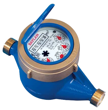
@smilvert I am afraid your water meter does not work. On many other watermeters the black spinning wheel is somewhat bigger and has a small mirror attached. The light from the IR LED is reflected by the mirror and the IR sensor picks up the reflection as a pulse every rotation (in your case 0.5 L). I suggest you buy another water meter that has a sensor build in and provides you with a direct signal. In my home I have separate water meters for each water consumer (such shower, hot water, kitchen, etc.).
I am using a Honeywell C7195A2001B which has a hall sensor that pulses at 7 Hz per liter/min, so you will get 420 pulses per liter. These meters are typically used in boiler or central heating systems that also can provide hot water for your shower. You need to modify the source code a bit to handle the high pulse frequency, but the nice thing is that the measurement is very accurate.
regards
Bart
-
I having problem to place the tcrt5000 on the correct place. Can anyone please show where to put it? Is it over the black (that spins every 0.5 l)?
I have this type of water meter
-
@smilvert You could try a magnometer. I successfully used one on my gas meter that didn't have a magnet in it. Look up "gas meter using a magnometer" in this forum. The code is much different than using the standard water meter sketch.
@smilvert @dpcr
I really doubt this type of water meter having a magnet to sense. Gas meters often are prepared to use a special reed swich to be mounted somewhere outside on the enclosure, and the magnet comes pretty close to the enclosure to be sensed.I somewhere found a different solution approach using a modified TCRT5000 board with green LED and a specific lightsensor (see here for details, german).
The idea behind it is to use complementary (green) light to one of the red pointer wheels to improve contrast when the small pointer passes.
I recently did some first test wrt. to this, but different to the mentioned solution, I used the original LED/sensor places to connect these two parts (and also changed the resistors values). Unfortunately, I wasn't able to test it "at the right place" until now. As far as I can see, the TCRT5000 inside just also consist of two seperate parts inside a housing. So you may try to do it like that: just pull of the plastic housing, change the LED (see TCRT datasheet which one) with a green one, focus LED and sensor a little more than normal and see, if you get reasonable results whith the trimming resistor.
Glad for feedback, if this works...
Controller: FHEM; MySensors: 2.3.1, RS485,nRF24,RFM69, serial Gateways
-
@smilvert @dpcr
I really doubt this type of water meter having a magnet to sense. Gas meters often are prepared to use a special reed swich to be mounted somewhere outside on the enclosure, and the magnet comes pretty close to the enclosure to be sensed.I somewhere found a different solution approach using a modified TCRT5000 board with green LED and a specific lightsensor (see here for details, german).
The idea behind it is to use complementary (green) light to one of the red pointer wheels to improve contrast when the small pointer passes.
I recently did some first test wrt. to this, but different to the mentioned solution, I used the original LED/sensor places to connect these two parts (and also changed the resistors values). Unfortunately, I wasn't able to test it "at the right place" until now. As far as I can see, the TCRT5000 inside just also consist of two seperate parts inside a housing. So you may try to do it like that: just pull of the plastic housing, change the LED (see TCRT datasheet which one) with a green one, focus LED and sensor a little more than normal and see, if you get reasonable results whith the trimming resistor.
Glad for feedback, if this works...
-
@rejoe2 A magnetometer doesn't need a magnet to work, my gas meter doesn't have a magnet and it works fine. Most all smartphones have magnetometers in them to sense direction. However your solution looks to work as well and probably with less code.
@dpcr Thanks for clarification.
Today there was a new post that may be of interest wrt. to the "green" LED sensing modification: https://forum.fhem.de/index.php?action=post;quote=702342;topic=71341.0;last_msg=702342
This one seems to be close to a "professional" solution also wrt. to the other parts used (but most likely not on a TCRT5000-Base)... -
I have a question and need some advise,
is it possible to expand the sketch to two meters.
In my case I want to combine a this Water Meter with a Gas Meter.
Can both meters use an interrupt, each?@rpunkt welcome to the MySensors community!
it depends on which microcontroller you use, and what type of interrupt.
Atmega328 can use pin 2 and 3 at the same time by merging the sketches. More/other pins can be used but that will require some code changes.
-
I having problem to place the tcrt5000 on the correct place. Can anyone please show where to put it? Is it over the black (that spins every 0.5 l)?
I have this type of water meter
@smilvert
I also have same meter as the picture. Yesterday I installed my sensor
I took a TCRT5000 IR sensor, https://www.mysensors.org/store/water
A cap from a soda bottle, cut it so it fits above left red wheel(X0,0001) which means one lap i 1 liter
It works but it counts little bit wrong, I have change theif (interval<500000L)to
if (interval<2500000L)but anyway it counts about 3 times to much. I will check it later today
-
@smilvert
I also have same meter as the picture. Yesterday I installed my sensor
I took a TCRT5000 IR sensor, https://www.mysensors.org/store/water
A cap from a soda bottle, cut it so it fits above left red wheel(X0,0001) which means one lap i 1 liter
It works but it counts little bit wrong, I have change theif (interval<500000L)to
if (interval<2500000L)but anyway it counts about 3 times to much. I will check it later today
@flopp
This didn't worked so well, I got a lot of errors everytime nRF was sending data, then I got one pulse.
Anyone know how to protect the digital input to NOT fall when nRF sends?
Wait, when I was writing this text :) I just remember that nRF is using Pin 2, is that correct?
I will try to use pin 3 instead, as interrupt pin