💬 Building a wired RS485 sensor network
-
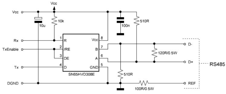
The 510 ohm pull up and pull down resistors are usually mounted on the master side. Theoretically it
would be best to install it in the middle of your bus line. The 120 ohm termination resistor must always
be used on distances greater than 1 meter and/or baud rates higher than 9600. It’s best to install it as a
norm as noise and reflections will cause havoc on your communication once implemented in the field.
The termination resistors should be mounted at both ends of the bus line. Please note that adding bias
resistors will load the driver IC output. With the indicated values the max number of units on the bus
line is limited to eight 12kΩ, sixteen 24kΩ, or thirty-two 48kΩ units.
For further protection transient suppressors can be installed across the differential lines, from the Vcc to
D+ and from GND to D-.!
-
Google for simple Modbus Master dcouments (arduino forum)
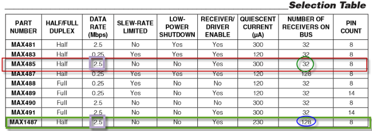
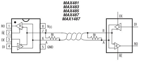
The MAX485 is not the best RS485 chip because of it's own internal impedance.
The chip in the diagram can be change by MAX485, MAX...
https://datasheets.maximintegrated.com/en/ds/MAX1487-MAX491.pdf
-
Hi, I'm building my home automation system and I have UTP cables cat5e in walls going to my wall switches. I have four cables, 5 nodes on one cable, 2 nodes on the second cable, and one node on 3rd and one 4th cable. 9 nodes. I know that the RS485 should be connected in parallel on single twisted pair but i cant change cables now cause my walls are painted etc.. So I have few problems, nodes stops working, i need to reset them few times, after few days the network stops to work and i start to search for an answers here. I changed numbers of SOH from 1 to 3 in 274 line of MyTransportRS485.cpp and now I think the network working better. I have 120ohm resistor in every node. You think that I should remove them ? Nodes are max 10 meters from the gateway so the cable lengths aren't so long.
-
@nofox
If you have got one free pair of wires in cat5e cable, it is easy to convert your "star" topology to pure 485 bus topology with terminal resistors on both ends only. -
@nofox it's what gohan stated, the 120ohm resistors should only put on the first and last node of you network. And you can only use a "bus" network topology for RS485.You should use the other wires of you Ethernet cable to accomplish this like kimot wrote.
-
Ok, so i switched my RS485 network to "bus". I desolder all of 120ohm resistors and have them only on both ends of the bus. RS485 to Ethernet gateway is in the middle of the wire. There are still some problems.. When I switching on the power and reading debug from gate I see that only 4 from 9 nodes are presenting. I need to reset other nodes manually to get them properly presented to the gateway. What am I doing wrong ? I need help I think.. Maybe its caused by the fact that all nodes powering on at the same time and there are many collisions on the RS485 bus ?? Maybe I should add some different delay() to setup part of my sketches to give, a time for every single node to present to the gateway ? Someone have successful working rs485 mysensors network here ?
This is code for one of my nodes with buttons, relays and temperature sensor:
#define MY_NODE_ID 8

// Enable debug prints to serial monitor
#define MY_DEBUG

// Enable RS485 transport layer
#define MY_RS485

// Define this to enables DE-pin management on defined pin
#define MY_RS485_DE_PIN 2

// Set RS485 baud rate to use
#define MY_RS485_BAUD_RATE 9600

#include <SPI.h>
#include <MySensors.h>
#include <Bounce2.h>
#include <DallasTemperature.h>
#include <OneWire.h>
#include <OneButton.h>

// define actions for OneButton function
typedef enum {
  ACTION_OFF_1,  // set relay "OFF".
  ACTION_ON_1,   // set relay "ON"
  ACTION_OFF_2,
  ACTION_ON_2
}
MyActions;

MyActions nextAction_1 = ACTION_OFF_1;
MyActions nextAction_2 = ACTION_OFF_2;

// define Arduino I/O pins for relays
#define RELAY_1  3 // Arduino Digital I/O pin number for first relay
#define RELAY_2  5 // Arduino Digital I/O pin number for first relay
#define RELAY_ON 1  // GPIO value to write to turn on attached relay
#define RELAY_OFF 0 // GPIO value to write to turn off attached relay

// configure parameters for 1Wire temp sensor
#define COMPARE_TEMP 1
#define ONE_WIRE_BUS 6
#define MAX_ATTACHED_DS18B20 16

// define CHILD IDs for relays and virtual multiaction click/doubleclick/longpress buttons
#define CHILD_ID_11 11 // child id for first relay and first button single click
#define CHILD_ID_12 12 // child id for second relay and second button single click
// #define CHILD_ID_13 13 // child id for first button single click (in this version not active because single click is attached directly to relay state)
#define CHILD_ID_14 14 // child id for first button double click
#define CHILD_ID_15 15 // child id for first button long press
// #define CHILD_ID_16 16 // child id for second button single click (in this version not active because single click is attached directly to relay state)
#define CHILD_ID_17 17 // child id for second button double click
#define CHILD_ID_18 18 // child id for second button long press

// define variables for temperature (and other) 1Wire Sensors
long previousMillis = 0;
long sensorInterval = 60000; // interval for temperature measurement
long HI_interval = 1000;
OneWire oneWire(ONE_WIRE_BUS);
DallasTemperature sensors(&oneWire);

float lastTemperature[MAX_ATTACHED_DS18B20];
int numSensors=0;
bool recivedConfig = false;
bool metric = true;

// define Arduino Digital I/O pins for OneButton function
OneButton BUTTON_1(7, true); // Arduino Digital I/O pin number for first physical button
OneButton BUTTON_2(10, true); // Arduino Digital I/O pin number for second physical button

bool V1_BUTTON_1; // set variable for virtual one click button 1
bool V2_BUTTON_1; // set variable for virtual double click button 1
bool V3_BUTTON_1; // set variable for virtual long press button 1

bool V1_BUTTON_2; // set variable for virtual one click button 2
bool V2_BUTTON_2; // set variable for virtual one click button 2
bool V3_BUTTON_2; // set variable for virtual one click button 2


bool state1; // variable for RELAY_1 states
bool state2; // variable for RELAY_2 states

void before()
{

 sensors.begin();

}

//define messages for diferent type of sensors CHILD_IDs used
MyMessage msg0(0,V_TEMP); // temperature sensor message
MyMessage msg11(CHILD_ID_11, V_LIGHT); // first relay & single click message
MyMessage msg12(CHILD_ID_12, V_LIGHT); // second relay & single click message

// MyMessage msg13(CHILD_ID_13, V_LIGHT); // button 1 Single click
MyMessage msg14(CHILD_ID_14, V_LIGHT); // button 1 Double click
MyMessage msg15(CHILD_ID_15, V_LIGHT); // button 1 Long press

// MyMessage msg16(CHILD_ID_16, V_LIGHT); // button 2 Single click
MyMessage msg17(CHILD_ID_17, V_LIGHT); // button 2 Dobule click
MyMessage msg18(CHILD_ID_18, V_LIGHT); // button 2 Long press

void setup()
{

digitalWrite(RELAY_1, RELAY_OFF); // Set first relay state and pin mode
 pinMode(RELAY_1, OUTPUT);

state1 = loadState(CHILD_ID_11);  // Set relay to last known state (using eeprom storage)
 digitalWrite(RELAY_1, state1?RELAY_ON:RELAY_OFF);

digitalWrite(RELAY_2, RELAY_OFF); // Set second relay state and pin mode
 pinMode(RELAY_2, OUTPUT);

state2 = loadState(CHILD_ID_12);  // Set relay to last known state (using eeprom storage)
 digitalWrite(RELAY_2, state2?RELAY_ON:RELAY_OFF);


// sending states of relays after node bootup
send(msg11.set(state1));
send(msg12.set(state2));

// attaching physical BUTTON_1 to OneButton function actions
BUTTON_1.attachClick(singleclick_BUTTON_1);
BUTTON_1.attachDoubleClick(doubleclick_BUTTON_1);
BUTTON_1.attachLongPressStop(longpress_BUTTON_1);
// attaching physical BUTTON_2 to OneButton function actions
BUTTON_2.attachClick(singleclick_BUTTON_2);
BUTTON_2.attachDoubleClick(doubleclick_BUTTON_2);
BUTTON_2.attachLongPressStop(longpress_BUTTON_2);
// setup for temperature sensor
sensors.setWaitForConversion(false);

}

void presentation()
{
    sendSketchInfo("pokoiczek_puszka_1", "1.0");

    numSensors = sensors.getDeviceCount();

  // Present all sensors to controller
  for (int i=0; i<numSensors && i<MAX_ATTACHED_DS18B20; i++) {
     present(i, S_TEMP);
  }

    present(CHILD_ID_11, S_LIGHT);
    present(CHILD_ID_12, S_LIGHT);

    // present(CHILD_ID_13, S_LIGHT);
    present(CHILD_ID_14, S_LIGHT);
    present(CHILD_ID_15, S_LIGHT);

    // present(CHILD_ID_16, S_LIGHT);
    present(CHILD_ID_17, S_LIGHT);
    present(CHILD_ID_18, S_LIGHT);

}


void loop()
{

  temperatureCheck(); // tmperature check function

  // states for nextAction of OneButton function
  if(state1 == HIGH)
    {
      nextAction_1 = ACTION_OFF_1;
    }
    else
    {
      nextAction_1 = ACTION_ON_1;
    }

  BUTTON_1.tick();  // reading state of first physical button

  if(state2 == HIGH)
    {
      nextAction_2 = ACTION_OFF_2;
    }
    else
    {
      nextAction_2 = ACTION_ON_2;
    }

  BUTTON_2.tick(); // // reading state of second physical button

}

void singleclick_BUTTON_1()
 {
  if (nextAction_1 == ACTION_OFF_1 )
    {
      nextAction_1 = ACTION_ON_1;
      send(msg11.set(HIGH?false:true), true);
    }
  else
    {
    nextAction_1 = ACTION_OFF_1;
    send(msg11.set(LOW?false:true), true);
    }
  // send(msg13.set(LOW ? 1 : 0));
  // send(msg13.set(HIGH ? 1 : 0));
 }

void doubleclick_BUTTON_1()
{
   send(msg14.set(LOW ? 1 : 0));
   send(msg14.set(HIGH ? 1 : 0));
}

void longpress_BUTTON_1()
{
   send(msg15.set(LOW ? 1 : 0));
   send(msg15.set(HIGH ? 1 : 0));
}

void singleclick_BUTTON_2()
{

   if (nextAction_2 == ACTION_OFF_2 )
    {
      nextAction_2 = ACTION_ON_2;
      send(msg12.set(HIGH?false:true), true);
    }
  else
    {
    nextAction_2 = ACTION_OFF_2;
    send(msg12.set(LOW?false:true), true);
    }

  // send(msg16.set(LOW ? 1 : 0));
  // send(msg16.set(HIGH ? 1 : 0));
}

void doubleclick_BUTTON_2()
{
   send(msg17.set(LOW ? 1 : 0));
   send(msg17.set(HIGH ? 1 : 0));
}

void longpress_BUTTON_2()
{
   send(msg18.set(LOW ? 1 : 0));
   send(msg18.set(HIGH ? 1 : 0));
}

void temperatureCheck()
{
 unsigned long currentMillis = millis();
 if(currentMillis - previousMillis > sensorInterval)
  {
    previousMillis = currentMillis;

  // Fetch temperatures from Dallas sensors
  sensors.requestTemperatures();
  // query conversion time and sleep until conversion completed
  int16_t conversionTime = sensors.millisToWaitForConversion(sensors.getResolution());
  // sleep() call can be replaced by wait() call if node need to process incoming messages (or if node is repeater)
  wait(conversionTime);
  // Read temperatures and send them to controller
  for (int i=0; i<numSensors && i<MAX_ATTACHED_DS18B20; i++) {
    // Fetch and round temperature to one decimal
    float temperature = static_cast<float>(static_cast<int>((getControllerConfig().isMetric?sensors.getTempCByIndex(i):sensors.getTempFByIndex(i)) * 10.)) / 10.;
    // Only send data if temperature has changed and no error
    #if COMPARE_TEMP == 1
    if (lastTemperature[i] != temperature && temperature != -127.00 && temperature != 85.00) {
    #else
    if (temperature != -127.00 && temperature != 85.00) {
    #endif
      // Send in the new temperature
      send(msg0.setSensor(i).set(temperature,1));
      // Save new temperatures for next compare
      lastTemperature[i]=temperature;
    }
  }

}

}

void receive(const MyMessage &message)
{
  if (message.type == V_STATUS && message.sensor == 11) {
    // Change relay state
    state1 = message.getBool();
    digitalWrite(RELAY_1, state1?RELAY_ON:RELAY_OFF);
    // Store state in eeprom
    saveState(CHILD_ID_11, state1);

   // send(msg11.set(state1));

     // Write some debug info
    Serial.print("Incoming change for sensor:");
    Serial.print(message.sensor);
    Serial.print(", New status: ");
    Serial.println(message.getBool());
  }
  else if (message.type == V_STATUS && message.sensor == 12) {

    state2 = message.getBool();
    digitalWrite(RELAY_2, state2?RELAY_ON:RELAY_OFF);

    saveState(CHILD_ID_12, state2);

   // send(msg12.set(state2));

    // Write some debug info
    Serial.print("Incoming change for sensor:");
    Serial.print(message.sensor);
    Serial.print(", New status: ");
    Serial.println(message.getBool());
  }
}
I'm using OneButton library to get different actions when i'm clicking once, twice and holding buttons.
-
Nofox,
- The 510 ohm pull up and pull down resistors (between A (D+) and 5V / between B (D-) and ground) are usually mounted on the master side (which is your gateway). Theoretically it would be best to install it in the middle of your bus line.
- check if your power supply has enough power to feed all your nodes
- check that all the ground lines of your boards are connected with each other.
MySensors 2.3.2; contr:Domoticz; layer: RS485, nRF24; gw: Ethernet, Serial
-
Nofox,
- The 510 ohm pull up and pull down resistors (between A (D+) and 5V / between B (D-) and ground) are usually mounted on the master side (which is your gateway). Theoretically it would be best to install it in the middle of your bus line.
- check if your power supply has enough power to feed all your nodes
- check that all the ground lines of your boards are connected with each other.
@ArduiSens Thanks for your reply! I have found few post here on MYS Forum about biasing rs485 line with pull up and pull down resistors and I will try to do this tomorrow. I'm using standard rs485 module from aliexpress on the gateway side. There are pullups and pulldowns there but they are two 10k resistors, I will change them to 510 as you mentioned.
All of my wired sensors, gateway and RPi are powered form 10A buffered power supply. I've checked voltage on every node. I have 5.25V on power supply pins in the middle of the line and 5.21 on both ends of line. I'm using one twisted pair for Vcc and one for GND. The bus is about 15 meter long form one end to another.
As I mentioned above all of nodes are supplied from one power supply so the grounds are all connected. -
Hello again. I've soldered this two pull-ups resistors like @ArduiSens wrote before. Now I think the network works much much better but after 24 hours of using something hangs and i can't turn of the light with buttons and with OpenHab also. I think the gateway freezing because after I reset only gateway all starts to work normal when i'm pressing wall switches. I need to reboot controller because after gateway reset OpenHab won't communicate with the gateway... Please take a look at my gateway sketch:
// Enable debug prints to serial monitor #define MY_DEBUG // Enable and select radio type attached // #define MY_RADIO_NRF24 // #define MY_RADIO_RFM69 #define MY_NODE_ID 0 // Enable RS485 transport layer #define MY_RS485 // Define this to enables DE-pin management on defined pin #define MY_RS485_DE_PIN 2 // Set RS485 baud rate to use #define MY_RS485_BAUD_RATE 9600 // #define MY_GATEWAY_MQTT_CLIENT // Enable gateway ethernet module type #define MY_GATEWAY_W5100 // W5100 Ethernet module SPI enable (optional if using a shield/module that manages SPI_EN signal) // #define MY_W5100_SPI_EN 4 // Enable Soft SPI for NRF radio (note different radio wiring is required) // The W5100 ethernet module seems to have a hard time co-operate with // radio on the same spi bus. #if !defined(MY_W5100_SPI_EN) && !defined(ARDUINO_ARCH_SAMD) #define MY_SOFTSPI #define MY_SOFT_SPI_SCK_PIN 14 #define MY_SOFT_SPI_MISO_PIN 16 #define MY_SOFT_SPI_MOSI_PIN 15 #endif // When W5100 is connected we have to move CE/CSN pins for NRF radio // #ifndef MY_RF24_CE_PIN // #define MY_RF24_CE_PIN 5 // #endif // #ifndef MY_RF24_CS_PIN // #define MY_RF24_CS_PIN 6 // #endif // Enable to UDP // #define MY_USE_UDP #define MY_IP_ADDRESS 192,168,0,66 // If this is disabled, DHCP is used to retrieve address // Renewal period if using DHCP //#define MY_IP_RENEWAL_INTERVAL 60000 // The port to keep open on node server mode / or port to contact in client mode #define MY_PORT 5003 // Controller ip address. Enables client mode (default is "server" mode). // Also enable this if MY_USE_UDP is used and you want sensor data sent somewhere. //#define MY_CONTROLLER_IP_ADDRESS 192, 168, 0, 70 // The MAC address can be anything you want but should be unique on your network. // Newer boards have a MAC address printed on the underside of the PCB, which you can (optionally) use. // Note that most of the Ardunio examples use "DEAD BEEF FEED" for the MAC address. #define MY_MAC_ADDRESS 0xDE, 0xAD, 0xBE, 0xEF, 0xFE, 0xED // Set this node's subscribe and publish topic prefix // #define MY_MQTT_PUBLISH_TOPIC_PREFIX "mygateway1-out" // #define MY_MQTT_SUBSCRIBE_TOPIC_PREFIX "mygateway1-in" // Set MQTT client id // #define MY_MQTT_CLIENT_ID "mysensors-1" // Enable these if your MQTT broker requires usenrame/password //#define MY_MQTT_USER "username" //#define MY_MQTT_PASSWORD "password" // Enable inclusion mode // #define MY_INCLUSION_MODE_FEATURE // Enable Inclusion mode button on gateway //#define MY_INCLUSION_BUTTON_FEATURE // Set inclusion mode duration (in seconds) // #define MY_INCLUSION_MODE_DURATION 60 // Digital pin used for inclusion mode button //#define MY_INCLUSION_MODE_BUTTON_PIN 3 // Set blinking period #define MY_DEFAULT_LED_BLINK_PERIOD 300 // Flash leds on rx/tx/err // Uncomment to override default HW configurations //#define MY_DEFAULT_ERR_LED_PIN 7 // Error led pin //#define MY_DEFAULT_RX_LED_PIN 8 // Receive led pin //#define MY_DEFAULT_TX_LED_PIN 9 // Transmit led pin #if defined(MY_USE_UDP) #include <EthernetUdp.h> #endif #include <Ethernet.h> #include <MySensors.h> void setup() { } void loop() { } -
@gohan I'm using soft SPI ? Where ? I taught that there are
#if !defined(MY_W5100_SPI_EN) && !defined(ARDUINO_ARCH_SAMD)
#define MY_SOFTSPI
#define MY_SOFT_SPI_SCK_PIN 14
#define MY_SOFT_SPI_MISO_PIN 16
#define MY_SOFT_SPI_MOSI_PIN 15
#endif
so when #define MY_W5100_SPI_EN 4 is commented I'm using hardware SPI ? What should i change than ? Comment the whole #if .... part ??
-
Forget it, I was on mobile and couldn't see well the code. Do you have IDE, boards definitions up to date? Did you try latest version of mysensors in development branch?
@gohan I have IDE 1.6.11 and boards definition 1.6.11 because on newer boards definition I've got boot loop on gateway. I'm using 2.1.1 MySensors library. Maybe I should mention that I can ping my gateway without any problems, only rs485 part seems not responding..
-
Hello again. After a week of thinking and hard work i finally got RS485 network working very close to what I want. I've done everything like it was mentioned here before. Fully bus-like network, termination only on both ends of line and pull-up and pull-down on the gateway. I also change MySensors library to newest 2.1 beta branch. All nodes working very good for last month but some times one node hanging and I can't control it via OpenHab or built in switch. I don't know what cause this behavior. I turn on watchdog timers in every nodes and theoretically when node hangs, watchdog should reboot arduino after 8 seconds. Practically it won't reboot my node.. It seems like the node don't really hangs but the communication stops.. Is it possible that one node can loose connection while other nodes on the same bus/wires working like a charm ?