RGBW setup
-
Hello,
My problem is with my RGBWW LED strip, that all LED are ON, node receives commands, but doesn't do anything when receives it.
I have bought this RGBWW LED strip.
It has 5 inputs: 12V; RED; GREEN; BLUE; and WARM WHITE input. So here are 3 inputs for (RGB) collors and 1 for White color.
I try to build a node from @LastSamurai manuals and I use his shematics from
MySensors RGBW Controller.
I did one change, instead of using IRLML2502 Mosfet, I use IRLZ44N Mosfet.I converted exsisting code to 2.0.0 version.
/**
Based on the MySensors Project: http://www.mysensors.org

This sketch controls a (analog)RGBW strip by listening to new color values from a (domoticz) controller and then fading to the new color.

Version 1.0 - Changed pins and gw definition
Version 0.9 - Oliver Hilsky

TODO
safe/request values after restart/loss of connection
*/

#define MY_DEBUG
#define MY_RADIO_NRF24
#define MY_NODE_ID 6

// Load mysensors library
#include <MySensors.h>
// Load Serial Peripheral Interface library
#include <SPI.h>

#define SN   "RGBW Fensterwand"
#define SV   "v1.0 29042016"

// Arduino pin attached to driver pins
#define RED_PIN 3
#define WHITE_PIN 9	// this is not a pwm pin! change it if you want pwm
#define GREEN_PIN 5
#define BLUE_PIN 6
#define NUM_CHANNELS 4 // how many channels, RGBW=4 RGB=3...

#define SENSOR_ID 1

// Smooth stepping between the values
#define STEP 1
#define INTERVAL 10
const int pwmIntervals = 255;
float R; // equation for dimming curve

// change the pins to free up the pwm pin for led control
#define MY_RF24_CE_PIN 4    // Radio specific settings for RF24
#define MY_RF24_CS_PIN 10 // Radio specific settings for RF24 (you'll find similar config for RFM69)

// Stores the current color settings
byte channels[4] = {RED_PIN, GREEN_PIN, BLUE_PIN, WHITE_PIN};
byte values[4] = {100, 100, 100, 100};
byte target_values[4] = {100, 100, 100, 100};


// stores dimming level
byte dimming = 100;
byte target_dimming = 100;

// tracks if the strip should be on of off
boolean isOn = true;

// time tracking for updates
unsigned long lastupdate = millis();

void presentation()
{
  // Present sketch (name, version)
  sendSketchInfo(SN, SV);

  // Register sensors (id, type, description, ack back)
  present(SENSOR_ID, S_RGBW_LIGHT, "RGBW test light", true);

  // request current values from gateway/controller
  //request(SENSOR_ID, S_RGBW_LIGHT);
}


void setup()
{
  // Set all channels to output (pin number, type)
  for (int i = 0; i < NUM_CHANNELS; i++) {
    pinMode(channels[i], OUTPUT);
  }

  // set up dimming
  R = (pwmIntervals * log10(2))/(log10(255));

  // init lights
  updateLights();

  // debug
  if (isOn) {
    Serial.println("RGBW is running...");
  }

  Serial.println("Waiting for messages...");
}

void loop()
{
  // and set the new light colors
  if (millis() > lastupdate + INTERVAL) {
    updateLights();
    lastupdate = millis();
  }
}

// callback function for incoming messages
void incomingMessage(const MyMessage &message) {

  Serial.print("Got a message - ");
  Serial.print("Messagetype is: ");
  Serial.println(message.type);

  // acknoledgment
  if (message.isAck())
  {
   	Serial.println("Got ack from gateway");
  }

  // new dim level
  else if (message.type == V_DIMMER) {
      Serial.println("Dimming to ");
      Serial.println(message.getString());
      target_dimming = message.getByte();
  }

  // on / off message
  else if (message.type == V_STATUS) {
    Serial.print("Turning light ");

    isOn = message.getInt();

    if (isOn) {
      Serial.println("on");
    } else {
      Serial.println("off");
    }
  }

  // new color value
  else if (message.type == V_RGBW) {
    const char * rgbvalues = message.getString();
    inputToRGBW(rgbvalues);
  }
}

// this gets called every INTERVAL milliseconds and updates the current pwm levels for all colors
void updateLights() {

  // update pin values -debug
  //Serial.println(greenval);
  //Serial.println(redval);
  //Serial.println(blueval);
  //Serial.println(whiteval);

  //Serial.println(target_greenval);
  //Serial.println(target_redval);
  //Serial.println(target_blueval);
  //Serial.println(target_whiteval);
  //Serial.println("+++++++++++++++");

  // for each color
  for (int v = 0; v < NUM_CHANNELS; v++) {

    if (values[v] < target_values[v]) {
      values[v] += STEP;
      if (values[v] > target_values[v]) {
        values[v] = target_values[v];
      }
    }

    if (values[v] > target_values[v]) {
      values[v] -= STEP;
      if (values[v] < target_values[v]) {
        values[v] = target_values[v];
      }
    }
  }

  // dimming
  if (dimming < target_dimming) {
    dimming += STEP;
    if (dimming > target_dimming) {
      dimming = target_dimming;
    }
  }
  if (dimming > target_dimming) {
    dimming -= STEP;
    if (dimming < target_dimming) {
      dimming = target_dimming;
    }
  }

  /*
  // debug - new values
  Serial.println(greenval);
  Serial.println(redval);
  Serial.println(blueval);
  Serial.println(whiteval);

  Serial.println(target_greenval);
  Serial.println(target_redval);
  Serial.println(target_blueval);
  Serial.println(target_whiteval);
  Serial.println("+++++++++++++++");
  */

  // set actual pin values
  for (int i = 0; i < NUM_CHANNELS; i++) {
    if (isOn) {
      // normal fading
      analogWrite(channels[i], dimming / 100.0 * values[i]);
      // non linear fading, idea from https://diarmuid.ie/blog/pwm-exponential-led-fading-on-arduino-or-other-platforms/
      //analogWrite(channels[i], pow (2, (values[i] / R)) - 1);
    } else {
      analogWrite(channels[i], 0);
    }
  }
}

// converts incoming color string to actual (int) values
// ATTENTION this currently does nearly no checks, so the format needs to be exactly like domoticz sends the strings
void inputToRGBW(const char * input) {
  Serial.print("Got color value of length: ");
  Serial.println(strlen(input));

  if (strlen(input) == 6) {
    Serial.println("new rgb value");
    target_values[0] = fromhex (& input [0]);
    target_values[1] = fromhex (& input [2]);
    target_values[2] = fromhex (& input [4]);
    target_values[3] = 0;
  } else if (strlen(input) == 9) {
    Serial.println("new rgbw value");
    target_values[0] = fromhex (& input [1]); // ignore # as first sign
    target_values[1] = fromhex (& input [3]);
    target_values[2] = fromhex (& input [5]);
    target_values[3] = fromhex (& input [7]);
  } else {
    Serial.println("Wrong length of input");
  }


  Serial.print("New color values: ");
  Serial.println(input);

  for (int i = 0; i < NUM_CHANNELS; i++) {
    Serial.print(target_values[i]);
    Serial.print(", ");
  }

  Serial.println("");
  Serial.print("Dimming: ");
  Serial.println(dimming);
}

// converts hex char to byte
byte fromhex (const char * str)
{
  char c = str [0] - '0';
  if (c > 9)
    c -= 7;
  int result = c;
  c = str [1] - '0';
  if (c > 9)
    c -= 7;
  return (result << 4) | c;
}
When I upload it - all LED's are on. I using NRF24L01+ radio, which connects with Domoticz and receives all comands successfully. I'am choosing color from domoticz color panel, color is transmitted to node, but no changes - no matter what chosen color, there always all LED's are on.
Node logs:
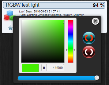
Starting sensor (RNNNA-, 2.0.0)
TSM:INIT
TSM:RADIO:OK
TSP:ASSIGNID:OK (ID=6)
TSM:FPAR
TSP:MSG:SEND 6-6-255-255 s=255,c=3,t=7,pt=0,l=0,sg=0,ft=0,st=bc:
TSM:FPAR
TSP:MSG:SEND 6-6-255-255 s=255,c=3,t=7,pt=0,l=0,sg=0,ft=0,st=bc:
TSM:FPAR
TSP:MSG:SEND 6-6-255-255 s=255,c=3,t=7,pt=0,l=0,sg=0,ft=0,st=bc:
TSM:FPAR
TSP:MSG:SEND 6-6-255-255 s=255,c=3,t=7,pt=0,l=0,sg=0,ft=0,st=bc:
!TSM:FPAR:FAIL
!TSM:FAILURE
TSM:PDT
TSM:INIT
TSM:RADIO:OK
TSP:ASSIGNID:OK (ID=6)
TSM:FPAR
TSP:MSG:SEND 6-6-255-255 s=255,c=3,t=7,pt=0,l=0,sg=0,ft=0,st=bc:
TSM:FPAR
TSP:MSG:SEND 6-6-255-255 s=255,c=3,t=7,pt=0,l=0,sg=0,ft=0,st=bc:
TSP:MSG:READ 0-0-6 s=255,c=3,t=8,pt=1,l=1,sg=0:0
TSP:MSG:FPAR RES (ID=0, dist=0)
TSP:MSG:PAR OK (ID=0, dist=1)
TSM:FPAR:OK
TSM:ID
TSM:CHKID:OK (ID=6)
TSM:UPL
TSP:PING:SEND (dest=0)
TSP:MSG:SEND 6-6-0-0 s=255,c=3,t=24,pt=1,l=1,sg=0,ft=0,st=ok:1
TSP:MSG:READ 0-0-6 s=255,c=3,t=25,pt=1,l=1,sg=0:1
TSP:MSG:PONG RECV (hops=1)
TSP:CHKUPL:OK
TSM:UPL:OK
TSM:READY
RGBW is running...
Waiting for messages...
TSP:MSG:SEND 6-6-0-0 s=255,c=3,t=15,pt=6,l=2,sg=0,ft=0,st=ok:0100
TSP:MSG:SEND 6-6-0-0 s=255,c=0,t=17,pt=0,l=5,sg=0,ft=0,st=ok:2.0.0
TSP:MSG:SEND 6-6-0-0 s=255,c=3,t=6,pt=1,l=1,sg=0,ft=0,st=ok:0
TSP:MSG:READ 0-0-6 s=255,c=3,t=15,pt=6,l=2,sg=0:0100
TSP:MSG:READ 0-0-6 s=255,c=3,t=6,pt=0,l=1,sg=0:M
TSP:MSG:SEND 6-6-0-0 s=255,c=3,t=11,pt=0,l=16,sg=0,ft=0,st=ok:RGBW Fensterwand
TSP:MSG:SEND 6-6-0-0 s=255,c=3,t=12,pt=0,l=13,sg=0,ft=0,st=ok:v1.0 29042016
TSP:MSG:SEND 6-6-0-0 s=1,c=0,t=27,pt=0,l=15,sg=0,ft=0,st=ok:RGBW test light
Request registration...
!TSP:MSG:SEND 6-6-0-0 s=255,c=3,t=26,pt=1,l=1,sg=0,ft=0,st=fail:2
TSP:MSG:READ 0-0-6 s=1,c=0,t=27,pt=0,l=15,sg=0:RGBW test light
TSP:MSG:SEND 6-6-0-0 s=255,c=3,t=26,pt=1,l=1,sg=0,ft=1,st=ok:2
TSP:MSG:READ 0-0-6 s=255,c=3,t=27,pt=1,l=1,sg=0:1
Node registration=1
Init complete, id=6, parent=0, distance=1, registration=1
TSP:MSG:READ 0-0-6 s=1,c=1,t=41,pt=0,l=6,sg=0:00FF24
TSP:MSG:READ 0-0-6 s=1,c=1,t=3,pt=0,l=2,sg=0:86
TSP:MSG:READ 0-0-6 s=1,c=1,t=41,pt=0,l=9,sg=0:#000000FF
TSP:MSG:READ 0-0-6 s=1,c=1,t=3,pt=0,l=2,sg=0:93
TSP:MSG:READ 0-0-6 s=1,c=1,t=41,pt=0,l=9,sg=0:#000000FF
TSP:MSG:READ 0-0-6 s=1,c=1,t=3,pt=0,l=3,sg=0:100
TSP:MSG:READ 0-0-6 s=1,c=1,t=41,pt=0,l=6,sg=0:E400FF
TSP:MSG:READ 0-0-6 s=1,c=1,t=3,pt=0,l=2,sg=0:58
TSP:MSG:READ 0-0-6 s=1,c=1,t=41,pt=0,l=9,sg=0:#000000FF
TSP:MSG:READ 0-0-6 s=1,c=1,t=3,pt=0,l=3,sg=0:100
TSP:MSG:READ 0-0-6 s=1,c=1,t=41,pt=0,l=6,sg=0:E400FF
TSP:MSG:READ 0-0-6 s=1,c=1,t=3,pt=0,l=1,sg=0:0
TSP:MSG:READ 0-0-6 s=1,c=1,t=41,pt=0,l=6,sg=0:E400FF
TSP:MSG:READ 0-0-6 s=1,c=1,t=3,pt=0,l=2,sg=0:94
TSP:MSG:READ 0-0-6 s=1,c=1,t=41,pt=0,l=6,sg=0:00FF7E
TSP:MSG:READ 0-0-6 s=1,c=1,t=3,pt=0,l=2,sg=0:94
TSP:MSG:READ 0-0-6 s=1,c=1,t=41,pt=0,l=6,sg=0:48FF00
TSP:MSG:READ 0-0-6 s=1,c=1,t=3,pt=0,l=2,sg=0:94
I try different code just for testing my connections from here, and code was working fine, colors whas changing like written.
So I rejected that problem is becose I use IRLZ44N instead of IRLML2502. Could someone verify that this is not becose of IRLZ44N?
Try different code from
here: RGBWDimmerDevice by tomas.kortell
...but was no difference. Node does not listening for commands.Maybe someone have some tips here, what I could change to get it working?
Other question: this LED strip gave 5 inputs (one of then are 12V), does it calls RGBW or RGBWW? By seller it is RGBWW and think it is becose it means Warm White, am I correct?
Thanks in advance!
-
Hello,
My problem is with my RGBWW LED strip, that all LED are ON, node receives commands, but doesn't do anything when receives it.
I have bought this RGBWW LED strip.
It has 5 inputs: 12V; RED; GREEN; BLUE; and WARM WHITE input. So here are 3 inputs for (RGB) collors and 1 for White color.
I try to build a node from @LastSamurai manuals and I use his shematics from
MySensors RGBW Controller.
I did one change, instead of using IRLML2502 Mosfet, I use IRLZ44N Mosfet.I converted exsisting code to 2.0.0 version.
/**
Based on the MySensors Project: http://www.mysensors.org

This sketch controls a (analog)RGBW strip by listening to new color values from a (domoticz) controller and then fading to the new color.

Version 1.0 - Changed pins and gw definition
Version 0.9 - Oliver Hilsky

TODO
safe/request values after restart/loss of connection
*/

#define MY_DEBUG
#define MY_RADIO_NRF24
#define MY_NODE_ID 6

// Load mysensors library
#include <MySensors.h>
// Load Serial Peripheral Interface library
#include <SPI.h>

#define SN   "RGBW Fensterwand"
#define SV   "v1.0 29042016"

// Arduino pin attached to driver pins
#define RED_PIN 3
#define WHITE_PIN 9	// this is not a pwm pin! change it if you want pwm
#define GREEN_PIN 5
#define BLUE_PIN 6
#define NUM_CHANNELS 4 // how many channels, RGBW=4 RGB=3...

#define SENSOR_ID 1

// Smooth stepping between the values
#define STEP 1
#define INTERVAL 10
const int pwmIntervals = 255;
float R; // equation for dimming curve

// change the pins to free up the pwm pin for led control
#define MY_RF24_CE_PIN 4    // Radio specific settings for RF24
#define MY_RF24_CS_PIN 10 // Radio specific settings for RF24 (you'll find similar config for RFM69)

// Stores the current color settings
byte channels[4] = {RED_PIN, GREEN_PIN, BLUE_PIN, WHITE_PIN};
byte values[4] = {100, 100, 100, 100};
byte target_values[4] = {100, 100, 100, 100};


// stores dimming level
byte dimming = 100;
byte target_dimming = 100;

// tracks if the strip should be on of off
boolean isOn = true;

// time tracking for updates
unsigned long lastupdate = millis();

void presentation()
{
  // Present sketch (name, version)
  sendSketchInfo(SN, SV);

  // Register sensors (id, type, description, ack back)
  present(SENSOR_ID, S_RGBW_LIGHT, "RGBW test light", true);

  // request current values from gateway/controller
  //request(SENSOR_ID, S_RGBW_LIGHT);
}


void setup()
{
  // Set all channels to output (pin number, type)
  for (int i = 0; i < NUM_CHANNELS; i++) {
    pinMode(channels[i], OUTPUT);
  }

  // set up dimming
  R = (pwmIntervals * log10(2))/(log10(255));

  // init lights
  updateLights();

  // debug
  if (isOn) {
    Serial.println("RGBW is running...");
  }

  Serial.println("Waiting for messages...");
}

void loop()
{
  // and set the new light colors
  if (millis() > lastupdate + INTERVAL) {
    updateLights();
    lastupdate = millis();
  }
}

// callback function for incoming messages
void incomingMessage(const MyMessage &message) {

  Serial.print("Got a message - ");
  Serial.print("Messagetype is: ");
  Serial.println(message.type);

  // acknoledgment
  if (message.isAck())
  {
   	Serial.println("Got ack from gateway");
  }

  // new dim level
  else if (message.type == V_DIMMER) {
      Serial.println("Dimming to ");
      Serial.println(message.getString());
      target_dimming = message.getByte();
  }

  // on / off message
  else if (message.type == V_STATUS) {
    Serial.print("Turning light ");

    isOn = message.getInt();

    if (isOn) {
      Serial.println("on");
    } else {
      Serial.println("off");
    }
  }

  // new color value
  else if (message.type == V_RGBW) {
    const char * rgbvalues = message.getString();
    inputToRGBW(rgbvalues);
  }
}

// this gets called every INTERVAL milliseconds and updates the current pwm levels for all colors
void updateLights() {

  // update pin values -debug
  //Serial.println(greenval);
  //Serial.println(redval);
  //Serial.println(blueval);
  //Serial.println(whiteval);

  //Serial.println(target_greenval);
  //Serial.println(target_redval);
  //Serial.println(target_blueval);
  //Serial.println(target_whiteval);
  //Serial.println("+++++++++++++++");

  // for each color
  for (int v = 0; v < NUM_CHANNELS; v++) {

    if (values[v] < target_values[v]) {
      values[v] += STEP;
      if (values[v] > target_values[v]) {
        values[v] = target_values[v];
      }
    }

    if (values[v] > target_values[v]) {
      values[v] -= STEP;
      if (values[v] < target_values[v]) {
        values[v] = target_values[v];
      }
    }
  }

  // dimming
  if (dimming < target_dimming) {
    dimming += STEP;
    if (dimming > target_dimming) {
      dimming = target_dimming;
    }
  }
  if (dimming > target_dimming) {
    dimming -= STEP;
    if (dimming < target_dimming) {
      dimming = target_dimming;
    }
  }

  /*
  // debug - new values
  Serial.println(greenval);
  Serial.println(redval);
  Serial.println(blueval);
  Serial.println(whiteval);

  Serial.println(target_greenval);
  Serial.println(target_redval);
  Serial.println(target_blueval);
  Serial.println(target_whiteval);
  Serial.println("+++++++++++++++");
  */

  // set actual pin values
  for (int i = 0; i < NUM_CHANNELS; i++) {
    if (isOn) {
      // normal fading
      analogWrite(channels[i], dimming / 100.0 * values[i]);
      // non linear fading, idea from https://diarmuid.ie/blog/pwm-exponential-led-fading-on-arduino-or-other-platforms/
      //analogWrite(channels[i], pow (2, (values[i] / R)) - 1);
    } else {
      analogWrite(channels[i], 0);
    }
  }
}

// converts incoming color string to actual (int) values
// ATTENTION this currently does nearly no checks, so the format needs to be exactly like domoticz sends the strings
void inputToRGBW(const char * input) {
  Serial.print("Got color value of length: ");
  Serial.println(strlen(input));

  if (strlen(input) == 6) {
    Serial.println("new rgb value");
    target_values[0] = fromhex (& input [0]);
    target_values[1] = fromhex (& input [2]);
    target_values[2] = fromhex (& input [4]);
    target_values[3] = 0;
  } else if (strlen(input) == 9) {
    Serial.println("new rgbw value");
    target_values[0] = fromhex (& input [1]); // ignore # as first sign
    target_values[1] = fromhex (& input [3]);
    target_values[2] = fromhex (& input [5]);
    target_values[3] = fromhex (& input [7]);
  } else {
    Serial.println("Wrong length of input");
  }


  Serial.print("New color values: ");
  Serial.println(input);

  for (int i = 0; i < NUM_CHANNELS; i++) {
    Serial.print(target_values[i]);
    Serial.print(", ");
  }

  Serial.println("");
  Serial.print("Dimming: ");
  Serial.println(dimming);
}

// converts hex char to byte
byte fromhex (const char * str)
{
  char c = str [0] - '0';
  if (c > 9)
    c -= 7;
  int result = c;
  c = str [1] - '0';
  if (c > 9)
    c -= 7;
  return (result << 4) | c;
}
When I upload it - all LED's are on. I using NRF24L01+ radio, which connects with Domoticz and receives all comands successfully. I'am choosing color from domoticz color panel, color is transmitted to node, but no changes - no matter what chosen color, there always all LED's are on.
Node logs:
Starting sensor (RNNNA-, 2.0.0)
TSM:INIT
TSM:RADIO:OK
TSP:ASSIGNID:OK (ID=6)
TSM:FPAR
TSP:MSG:SEND 6-6-255-255 s=255,c=3,t=7,pt=0,l=0,sg=0,ft=0,st=bc:
TSM:FPAR
TSP:MSG:SEND 6-6-255-255 s=255,c=3,t=7,pt=0,l=0,sg=0,ft=0,st=bc:
TSM:FPAR
TSP:MSG:SEND 6-6-255-255 s=255,c=3,t=7,pt=0,l=0,sg=0,ft=0,st=bc:
TSM:FPAR
TSP:MSG:SEND 6-6-255-255 s=255,c=3,t=7,pt=0,l=0,sg=0,ft=0,st=bc:
!TSM:FPAR:FAIL
!TSM:FAILURE
TSM:PDT
TSM:INIT
TSM:RADIO:OK
TSP:ASSIGNID:OK (ID=6)
TSM:FPAR
TSP:MSG:SEND 6-6-255-255 s=255,c=3,t=7,pt=0,l=0,sg=0,ft=0,st=bc:
TSM:FPAR
TSP:MSG:SEND 6-6-255-255 s=255,c=3,t=7,pt=0,l=0,sg=0,ft=0,st=bc:
TSP:MSG:READ 0-0-6 s=255,c=3,t=8,pt=1,l=1,sg=0:0
TSP:MSG:FPAR RES (ID=0, dist=0)
TSP:MSG:PAR OK (ID=0, dist=1)
TSM:FPAR:OK
TSM:ID
TSM:CHKID:OK (ID=6)
TSM:UPL
TSP:PING:SEND (dest=0)
TSP:MSG:SEND 6-6-0-0 s=255,c=3,t=24,pt=1,l=1,sg=0,ft=0,st=ok:1
TSP:MSG:READ 0-0-6 s=255,c=3,t=25,pt=1,l=1,sg=0:1
TSP:MSG:PONG RECV (hops=1)
TSP:CHKUPL:OK
TSM:UPL:OK
TSM:READY
RGBW is running...
Waiting for messages...
TSP:MSG:SEND 6-6-0-0 s=255,c=3,t=15,pt=6,l=2,sg=0,ft=0,st=ok:0100
TSP:MSG:SEND 6-6-0-0 s=255,c=0,t=17,pt=0,l=5,sg=0,ft=0,st=ok:2.0.0
TSP:MSG:SEND 6-6-0-0 s=255,c=3,t=6,pt=1,l=1,sg=0,ft=0,st=ok:0
TSP:MSG:READ 0-0-6 s=255,c=3,t=15,pt=6,l=2,sg=0:0100
TSP:MSG:READ 0-0-6 s=255,c=3,t=6,pt=0,l=1,sg=0:M
TSP:MSG:SEND 6-6-0-0 s=255,c=3,t=11,pt=0,l=16,sg=0,ft=0,st=ok:RGBW Fensterwand
TSP:MSG:SEND 6-6-0-0 s=255,c=3,t=12,pt=0,l=13,sg=0,ft=0,st=ok:v1.0 29042016
TSP:MSG:SEND 6-6-0-0 s=1,c=0,t=27,pt=0,l=15,sg=0,ft=0,st=ok:RGBW test light
Request registration...
!TSP:MSG:SEND 6-6-0-0 s=255,c=3,t=26,pt=1,l=1,sg=0,ft=0,st=fail:2
TSP:MSG:READ 0-0-6 s=1,c=0,t=27,pt=0,l=15,sg=0:RGBW test light
TSP:MSG:SEND 6-6-0-0 s=255,c=3,t=26,pt=1,l=1,sg=0,ft=1,st=ok:2
TSP:MSG:READ 0-0-6 s=255,c=3,t=27,pt=1,l=1,sg=0:1
Node registration=1
Init complete, id=6, parent=0, distance=1, registration=1
TSP:MSG:READ 0-0-6 s=1,c=1,t=41,pt=0,l=6,sg=0:00FF24
TSP:MSG:READ 0-0-6 s=1,c=1,t=3,pt=0,l=2,sg=0:86
TSP:MSG:READ 0-0-6 s=1,c=1,t=41,pt=0,l=9,sg=0:#000000FF
TSP:MSG:READ 0-0-6 s=1,c=1,t=3,pt=0,l=2,sg=0:93
TSP:MSG:READ 0-0-6 s=1,c=1,t=41,pt=0,l=9,sg=0:#000000FF
TSP:MSG:READ 0-0-6 s=1,c=1,t=3,pt=0,l=3,sg=0:100
TSP:MSG:READ 0-0-6 s=1,c=1,t=41,pt=0,l=6,sg=0:E400FF
TSP:MSG:READ 0-0-6 s=1,c=1,t=3,pt=0,l=2,sg=0:58
TSP:MSG:READ 0-0-6 s=1,c=1,t=41,pt=0,l=9,sg=0:#000000FF
TSP:MSG:READ 0-0-6 s=1,c=1,t=3,pt=0,l=3,sg=0:100
TSP:MSG:READ 0-0-6 s=1,c=1,t=41,pt=0,l=6,sg=0:E400FF
TSP:MSG:READ 0-0-6 s=1,c=1,t=3,pt=0,l=1,sg=0:0
TSP:MSG:READ 0-0-6 s=1,c=1,t=41,pt=0,l=6,sg=0:E400FF
TSP:MSG:READ 0-0-6 s=1,c=1,t=3,pt=0,l=2,sg=0:94
TSP:MSG:READ 0-0-6 s=1,c=1,t=41,pt=0,l=6,sg=0:00FF7E
TSP:MSG:READ 0-0-6 s=1,c=1,t=3,pt=0,l=2,sg=0:94
TSP:MSG:READ 0-0-6 s=1,c=1,t=41,pt=0,l=6,sg=0:48FF00
TSP:MSG:READ 0-0-6 s=1,c=1,t=3,pt=0,l=2,sg=0:94
I try different code just for testing my connections from here, and code was working fine, colors whas changing like written.
So I rejected that problem is becose I use IRLZ44N instead of IRLML2502. Could someone verify that this is not becose of IRLZ44N?
Try different code from
here: RGBWDimmerDevice by tomas.kortell
...but was no difference. Node does not listening for commands.Maybe someone have some tips here, what I could change to get it working?
Other question: this LED strip gave 5 inputs (one of then are 12V), does it calls RGBW or RGBWW? By seller it is RGBWW and think it is becose it means Warm White, am I correct?
Thanks in advance!
@jacikaas yes, WW is warm white. So the 5 "inputs" are
+12V
Red
Green
Blue
WhiteWhat happens if you connect the input of one of the mosfets to GND instead of the Arduino PWM pin? What happens if you connect the mosfet input to VCC instead?
Could you post a photo of your wiring?
I am using IRLZ44N for my kitchen light. I had to use a 3.3V->5V logic level shifter to get the mosfet to turn completely on, but you seem to have the opposite problem so that shouldn't be related.
If you uncomment all the nice serial debug statements, what does the output look like?
-
@jacikaas yes, WW is warm white. So the 5 "inputs" are
+12V
Red
Green
Blue
WhiteWhat happens if you connect the input of one of the mosfets to GND instead of the Arduino PWM pin? What happens if you connect the mosfet input to VCC instead?
Could you post a photo of your wiring?
I am using IRLZ44N for my kitchen light. I had to use a 3.3V->5V logic level shifter to get the mosfet to turn completely on, but you seem to have the opposite problem so that shouldn't be related.
If you uncomment all the nice serial debug statements, what does the output look like?
What happens if you connect the input of one of the mosfets to GND instead of the Arduino PWM pin?
I disconnect RED color MOSFET G (Gate) input from Arduino 3 input - then all red LED's turns off. When I connect it to GND - all red LED's are still turned of.
What happens if you connect the mosfet input to VCC instead?
When I connect to VCC - all red LED's turn on. And I thinks it shines brighter then connected to Arduino 3 PIN.
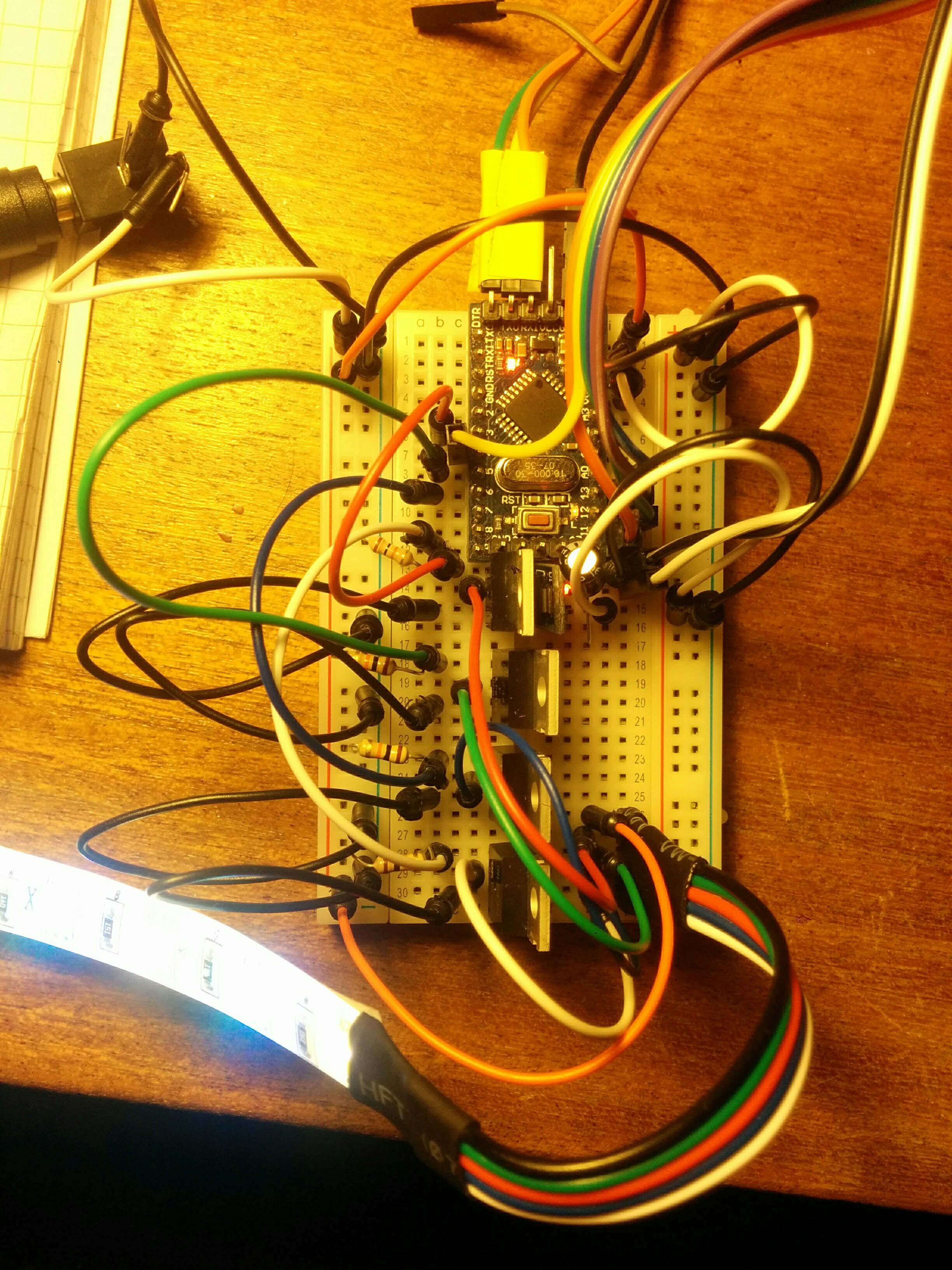
Could you post a photo of your wiring?
Of course. It's a bit messy on breadboard, but wiring made on same colors as RGBWW LED Strip. Here it is:
I am using IRLZ44N for my kitchen light. I had to use a 3.3V->5V logic level shifter to get the mosfet to turn completely on, but you seem to have the opposite problem so that shouldn't be related.
I'm using 5V Arduino Pro Mini, so I think it's ok with voltage?
If you uncomment all the nice serial debug statements, what does the output look like?
I uncomment serial debug statements, but variables in there isn't defined, and I'm not actualy know how I should describe them and where point them...
Voltage between Mosfet G and D terminals (for RED color) is 3.12V, when its connected to Arduino 3 PIN, other Mosfets voltage is lower and everyone is different. It seems like Arduino keeps opened PIN's.
-
What happens if you connect the input of one of the mosfets to GND instead of the Arduino PWM pin?
I disconnect RED color MOSFET G (Gate) input from Arduino 3 input - then all red LED's turns off. When I connect it to GND - all red LED's are still turned of.
What happens if you connect the mosfet input to VCC instead?
When I connect to VCC - all red LED's turn on. And I thinks it shines brighter then connected to Arduino 3 PIN.
Could you post a photo of your wiring?
Of course. It's a bit messy on breadboard, but wiring made on same colors as RGBWW LED Strip. Here it is:
I am using IRLZ44N for my kitchen light. I had to use a 3.3V->5V logic level shifter to get the mosfet to turn completely on, but you seem to have the opposite problem so that shouldn't be related.
I'm using 5V Arduino Pro Mini, so I think it's ok with voltage?
If you uncomment all the nice serial debug statements, what does the output look like?
I uncomment serial debug statements, but variables in there isn't defined, and I'm not actualy know how I should describe them and where point them...
Voltage between Mosfet G and D terminals (for RED color) is 3.12V, when its connected to Arduino 3 PIN, other Mosfets voltage is lower and everyone is different. It seems like Arduino keeps opened PIN's.
-
Hi, great to hear that someone else is using my project too. Perhaps we can get it to work for you too :)
First of all your mosfets should work too, I was using IRLZ44N mosfets too for my prototypes (although some people in the forum had problems with them I think).
All your leds turn on because the standard setting (when the node doesn't receive anything else) is to turn on every channel to 100 of 255.byte values[4] = {100, 100, 100, 100}; byte target_values[4] = {100, 100, 100, 100};Change that part if you don't want this behaviour.
The important part of your code for changing colors is the incomingMessage(const MyMessage &message) function. In your logs I am never seeing any serial output from that function. So I guess you never get any new messages with new values?! Try to find out why that method never gets called.
I haven't worked with mysensors 2.0 yet so it might be a problem with the conversion or just with your radio setup. With 1.5 and my node it works well (I have 5 nodes running atm). -
Hi, great to hear that someone else is using my project too. Perhaps we can get it to work for you too :)
First of all your mosfets should work too, I was using IRLZ44N mosfets too for my prototypes (although some people in the forum had problems with them I think).
All your leds turn on because the standard setting (when the node doesn't receive anything else) is to turn on every channel to 100 of 255.byte values[4] = {100, 100, 100, 100}; byte target_values[4] = {100, 100, 100, 100};Change that part if you don't want this behaviour.
The important part of your code for changing colors is the incomingMessage(const MyMessage &message) function. In your logs I am never seeing any serial output from that function. So I guess you never get any new messages with new values?! Try to find out why that method never gets called.
I haven't worked with mysensors 2.0 yet so it might be a problem with the conversion or just with your radio setup. With 1.5 and my node it works well (I have 5 nodes running atm).@LastSamurai : Great work. We had this working with Domoticz. Except only 1 color white did not respond after several color adjustments in Domoticz. PWM issue... We don't know. So currently I am using a Mi-Light controller. However with your post at my friends place we are going to try your solution. ;-) who wants to use mi-light if we can have MySensors. Just a question... With MiLight it is impossible to use White + RGB... WIth your code I think it should be possible to also use both LED simultaniously for a better color representation.. Don't know if it will melt the LED strip or fry the powersupply. Any suggestions??
-
@LastSamurai : Great work. We had this working with Domoticz. Except only 1 color white did not respond after several color adjustments in Domoticz. PWM issue... We don't know. So currently I am using a Mi-Light controller. However with your post at my friends place we are going to try your solution. ;-) who wants to use mi-light if we can have MySensors. Just a question... With MiLight it is impossible to use White + RGB... WIth your code I think it should be possible to also use both LED simultaniously for a better color representation.. Don't know if it will melt the LED strip or fry the powersupply. Any suggestions??
@sincze Thanks!
Concerning the pwm issue: you need to make sure that you use pins that support pwm (in an earlier version I used one pin that didn't; now I do but you have to move the radio to another pin).
You want to light up the white leds and the rgb leds at the same time? No problem for my node, it allows you to use every channel independently (see my post above, it's a 4 value array).The problem might be that you have to send the right message. Domoticz (the controller I am using) only send either rgb values or a white value, so only one of them gets light up. If you find a controller that sends different values it should work just fine though. You might have to change the inputToRGBW() method where my node interprets the message send from the controller).
I wish you good luck, if you need help just ask :)
-
Hi, great to hear that someone else is using my project too. Perhaps we can get it to work for you too :)
First of all your mosfets should work too, I was using IRLZ44N mosfets too for my prototypes (although some people in the forum had problems with them I think).
All your leds turn on because the standard setting (when the node doesn't receive anything else) is to turn on every channel to 100 of 255.byte values[4] = {100, 100, 100, 100}; byte target_values[4] = {100, 100, 100, 100};Change that part if you don't want this behaviour.
The important part of your code for changing colors is the incomingMessage(const MyMessage &message) function. In your logs I am never seeing any serial output from that function. So I guess you never get any new messages with new values?! Try to find out why that method never gets called.
I haven't worked with mysensors 2.0 yet so it might be a problem with the conversion or just with your radio setup. With 1.5 and my node it works well (I have 5 nodes running atm).@mfalkvidd @LastSamurai thanks a lot guys!
I remove pulldown resistors. I found code for RGB LED strip in here:
RGB_3DI adopt it for RGBW LED and add white LED's control:
/**
 * The MySensors Arduino library handles the wireless radio link and protocol
 * between your home built sensors/actuators and HA controller of choice.
 * The sensors forms a self healing radio network with optional repeaters. Each
 * repeater and gateway builds a routing tables in EEPROM which keeps track of the
 * network topology allowing messages to be routed to nodes.
 *
 * Created by Henrik Ekblad <henrik.ekblad@mysensors.org>
 * Copyright (C) 2013-2015 Sensnology AB
 * Full contributor list: https://github.com/mysensors/Arduino/graphs/contributors
 *
 * Documentation: http://www.mysensors.org
 * Support Forum: http://forum.mysensors.org
 *
 * This program is free software; you can redistribute it and/or
 * modify it under the terms of the GNU General Public License
 * version 2 as published by the Free Software Foundation.
 *
 *******************************
 *
 * REVISION HISTORY
 * Version 1.0 - Created by vil1driver
 *
 * DESCRIPTION
 * RGB led strip controled with three dimmers + one On/Off for run/stop rgb color cycle :p
 *
 */

#define SN   "RGB Led strip 3D"
#define SV   "v1"

// Enable debug prints to serial monitor
#define MY_DEBUG
#define MY_NODE_ID 6
// Enable and select radio type attached
#define MY_RADIO_NRF24
//#define MY_RADIO_RFM69

#define MY_RF24_CE_PIN 4    // Radio specific settings for RF24
#define MY_RF24_CS_PIN 10 // Radio specific settings for RF24 (you'll find similar config for RFM69)

#include <SPI.h>
#include <MySensors.h>

// Arduino pin attached to MOSFET Gate pin
#define RED_PIN 3
#define GREEN_PIN 5
#define BLUE_PIN 6
#define WHITE_PIN 9

// Define message name and type to send sensor info
MyMessage RedStatus(RED_PIN, V_DIMMER);
MyMessage GreenStatus(GREEN_PIN, V_DIMMER);
MyMessage BlueStatus(BLUE_PIN, V_DIMMER);
MyMessage WhiteStatus(WHITE_PIN, V_DIMMER);
MyMessage Status(1, V_DIMMER);
MyMessage rgbShowState(0, V_LIGHT);

// Serial.print translate sensor id to sensor name
char color[][9] = {"","","","RED","","GREEN","BLUE","","","WHITE"};

// Vars for rgbShow function
int redval = 0;
int greenval = 0;
int blueval = 0;
long time=0;
int isShow;

void setup()
{
  // Define pin mode (pin number, type)
  pinMode(RED_PIN, OUTPUT);
  pinMode(GREEN_PIN, OUTPUT);
  pinMode(BLUE_PIN, OUTPUT);
  pinMode(WHITE_PIN, OUTPUT);

  // Correct saved RGB value for first start
  saveState(RED_PIN, constrain((int8_t)loadState(RED_PIN), 0, 100));
  saveState(GREEN_PIN, constrain((int8_t)loadState(GREEN_PIN), 0, 100));
  saveState(BLUE_PIN, constrain((int8_t)loadState(BLUE_PIN), 0, 100));
  saveState(WHITE_PIN, constrain((int8_t)loadState(WHITE_PIN), 0, 100));

  // Get value from eeprom and write to output
  analogWrite(RED_PIN, 255 * loadState(RED_PIN) / 100);
  analogWrite(GREEN_PIN, 255 * loadState(GREEN_PIN) / 100);
  analogWrite(BLUE_PIN, 255 * loadState(BLUE_PIN) / 100);
  analogWrite(WHITE_PIN, 255 * loadState(WHITE_PIN) / 100);

  // Write some debug info
  Serial.print("Load from eeprom RED: ");
  Serial.print(loadState(RED_PIN));
  Serial.println("%");
  Serial.print("Load from eeprom GREEN: ");
  Serial.print(loadState(GREEN_PIN));
  Serial.println("%");
  Serial.print("Load from eeprom BLUE: ");
  Serial.print(loadState(BLUE_PIN));
  Serial.println("%");
  Serial.print("Load from eeprom WHITE: ");
  Serial.print(loadState(WHITE_PIN));
  Serial.println("%");

  // Send RGB value to controler (request ack back: true/false)
  Serial.println("Send eeprom value to controler");
  send( RedStatus.set(loadState(RED_PIN)), false );
  send( GreenStatus.set(loadState(GREEN_PIN)), false );
  send( BlueStatus.set(loadState(BLUE_PIN)), false );
  send( WhiteStatus.set(loadState(BLUE_PIN)), false );

  // Correct RGB show state for first start and load it (set to 'On' at first start)
  saveState(0, constrain((int8_t)loadState(0), 0, 1));
  isShow=loadState(0);

  // Send RGB show state to controler (request ack back: true/false)
  send( rgbShowState.set(isShow), false);

  if (isShow==1){Serial.println("RGB show running..."); }
  Serial.println("Ready to receive messages...");
}

void presentation()  {
  // Present sketch (name, version)
  sendSketchInfo(SN, SV);

  // Register sensors (id, type, description, ack back)
  present(RED_PIN, S_DIMMER, "present RED light", false);
  present(GREEN_PIN, S_DIMMER, "present GREEN light", false);
  present(BLUE_PIN, S_DIMMER, "present BLUE light", false);
  present(WHITE_PIN, S_DIMMER, "present WHITE light", false);
  present(0, S_LIGHT, "present Show button", false);
}

void loop()
{
  // Run RGB show if is set
  if (isShow==1)
  {
      rgbShow();
    analogWrite(RED_PIN, redval);
    analogWrite(GREEN_PIN, greenval);
    analogWrite(BLUE_PIN, blueval);
   }
}


void receive(const MyMessage &message)
{
  if (message.isAck())
  {
    Serial.println("Got ack from gateway");
  }
  if (message.type == V_LIGHT)
  {
    // Incoming on/off command sent from controller ("1" or "0")
    int lightState = message.getString()[0] == '1';

    // if receive RGB Show On commands, start the show
    if (message.sensor==0 && lightState==1){ rgbShowOn(); }
        // if receive RGB Show Off commands, stop the show
    else if (message.sensor==0 && lightState==0){ rgbShowOff(); }

    // if receive RGB switch On command
    else if (lightState==1)
    {
      // Write some debug info
            Serial.print("Incoming change for ");
            Serial.print(color[message.sensor]);
            Serial.println(": On");
            Serial.print("Load from eeprom: ");

      if ( loadState(message.sensor) == 0)
      {
        // Pick up last saved dimmer level from the eeprom
                analogWrite(message.sensor, 255 * loadState(10*message.sensor) / 100);
                // Save loaded value to current
                saveState(message.sensor, loadState(10*message.sensor));
                Serial.print(loadState(10*message.sensor));
                Serial.println("%");
                // Send value to controler
                Serial.println("Send value to controler");
                send(Status.setSensor(message.sensor).set(loadState(10*message.sensor)),false);
            }
            else
            {
                // Pick up last saved dimmer level from the eeprom
                analogWrite(message.sensor, 255 * loadState(message.sensor) / 100);
                Serial.print(loadState(message.sensor));
                Serial.println("%");
                // Send value to controler
                Serial.println("Send value to controler");
                send(Status.setSensor(message.sensor).set(loadState(message.sensor)),false);
            }
            // Stop the show if it's running
            if (isShow==1){ rgbShowStop(message.sensor); }
        }
    // if recieve switch Off command
    else if (lightState==0)
    {
      // Write output to 0 (Off)
            analogWrite(message.sensor, 0);
            // Save old value to eeprom if it'was not zero
            if ( loadState(message.sensor) != 0 )
            {
                saveState(10*message.sensor, constrain((int8_t)loadState(message.sensor), 0, 100));
            }
            // Save new value to eeprom
            saveState(message.sensor, 0);
            // Write some debug info
      Serial.print("Incoming change for ");
      Serial.print(color[message.sensor]);
      Serial.print(": ");
      Serial.println("Off");
            Serial.print("Store old value: ");
            Serial.print(loadState(10*message.sensor));
            Serial.println("%");
            // Send value to controler
            Serial.println("Send value to controler");
            send(Status.setSensor(message.sensor).set(loadState(message.sensor)),false);
      // Stop the show if it's running
      if (isShow==1){ rgbShowStop(message.sensor); }
    }
  }
  else if (message.type == V_DIMMER)
  {
      uint8_t incomingDimmerStatus = message.getByte();
      // limits range of sensor values to between 0 and 100
      incomingDimmerStatus = constrain((int8_t)incomingDimmerStatus, 0, 100);
      // Change Dimmer level
      analogWrite(message.sensor, 255 * incomingDimmerStatus / 100);
      //Save value to eeprom
      saveState(message.sensor, incomingDimmerStatus);
      // Write some debug info
      Serial.print("Incoming change for ");
      Serial.print(color[message.sensor]);
      Serial.print(": ");
      Serial.print(incomingDimmerStatus);
      Serial.println("%");
        // Send value to controler
        Serial.println("Send value to controler");
        send(Status.setSensor(message.sensor).set(loadState(message.sensor)),false);
      // Stop the show if it's running
      if (isShow==1){ rgbShowStop(message.sensor); }
    }
}

void rgbShow()
{
  time = millis();
  redval = 128+250*cos(2*PI/300000*time);
  greenval = 128+250*cos(2*PI/300000*time-222);
  blueval = 128+250*cos(2*PI/300000*time-111);
  // limits range of sensor values to between 0 and 255
  redval = constrain(redval, 0, 255);
  greenval = constrain(greenval, 0, 255);
  blueval = constrain(blueval, 0, 255);
}

void rgbShowOn()
{
  // define show On
  isShow=1;
  // Save state
  saveState(0, 1);
  // Write some debug info
  Serial.println("Show must go on");
}

void rgbShowOff()
{
  // define show Off
  isShow=0;
  // Save state
  saveState(0, 0);
  // Save RGB value to eeprom
  saveState(RED_PIN, 100 * redval / 255);
  saveState(GREEN_PIN, 100 * greenval / 255);
  saveState(BLUE_PIN, 100 * blueval / 255);
  // Write some debug info
  Serial.println("Stop the show");
  // Send actual RGB value and state to controler and request ack back (true/false)
  Serial.println("Send eeprom value to controler");
  send( RedStatus.set(loadState(RED_PIN)), false );
  send( GreenStatus.set(loadState(GREEN_PIN)), false );
  send( BlueStatus.set(loadState(BLUE_PIN)), false );
  send( rgbShowState.set(0), false);
}

void rgbShowStop(int sensor)
{
   // define show Off
   isShow=0;
   // Save state
   saveState(0, 0);
   // Write some debug info
   Serial.println("Stop the show");
   // Send actual RGB value and state to controler and request ack back (true/false)
   Serial.println("Send eeprom value to controler");
   if (sensor != RED_PIN)
   {
        saveState(RED_PIN, 100 * redval / 255);
        send( RedStatus.set(loadState(RED_PIN)), false );
    }
    if (sensor != GREEN_PIN)
    {
        saveState(GREEN_PIN, 100 * greenval / 255);
        send( GreenStatus.set(loadState(GREEN_PIN)), false );
    }
    if (sensor != BLUE_PIN)
    {
        saveState(BLUE_PIN, 100 * blueval / 255);
        send( BlueStatus.set(loadState(BLUE_PIN)), false );
    }
    send( rgbShowState.set(0), false);
}
This code works perfectly, so I could say my IRLZ44N is not broken. The biggest differences between codes is that with this one I need to control every color separately and it has "party" mode (show) :))) It's just nice to have. :)
Now I'm trying to add a physical button that could control white color on/off.@LastSamurai I will try to understand why I don't get new messages with Your code. I will inform when I will got something.
-
What version of Domoticz are you using? The original code relies on l6 and l9 message length to distinguish between RGB and RGBW, while recently Domoticz started to send l7 and l10 messages.
So I had a node that worked, but stopped working.
I changed 2 digits in the code and it works againAlso, in case of length 9/10 message, you don't need to parse RGBW values as Domoticz ALWAYS sends 000000FF in this case.
@Toyman Oh, do they? I am using the newest version from the beta channel: 3.5691. At least thats how I configured my instance. I don't know if the format changed (haven't checked recently), but my nodes are working just fine.
And yes that parsing is not needed that was just in case they changed it later. -
@Toyman Oh, do they? I am using the newest version from the beta channel: 3.5691. At least thats how I configured my instance. I don't know if the format changed (haven't checked recently), but my nodes are working just fine.
And yes that parsing is not needed that was just in case they changed it later.@LastSamurai yes. This is strange, I know, but that's what I observed in the node log.
I made a preliminary breadboard node, everything was working fine so I soldered it on a PCB, connected and… nothing happened. And then I noticed the change. As soon as I changed 6/9 to 7/10, the light was on :-) -
What version of Domoticz are you using? The original code relies on l6 and l9 message length to distinguish between RGB and RGBW, while recently Domoticz started to send l7 and l10 messages.
So I had a node that worked, but stopped working.
I changed 2 digits in the code and it works againAlso, in case of length 9/10 message, you don't need to parse RGBW values as Domoticz ALWAYS sends 000000FF in this case.
I'm using latest Beta version Domoticz V3.5727
In the logs, I can see that I receive 6 and 9 characters code:
Starting sensor (RNNNA-, 2.0.0)
TSM:INIT
TSM:RADIO:OK
TSP:ASSIGNID:OK (ID=6)
TSM:FPAR
TSP:MSG:SEND 6-6-255-255 s=255,c=3,t=7,pt=0,l=0,sg=0,ft=0,st=bc:
TSP:MSG:READ 0-0-6 s=255,c=3,t=8,pt=1,l=1,sg=0:0
TSP:MSG:FPAR RES (ID=0, dist=0)
TSP:MSG:PAR OK (ID=0, dist=1)
TSM:FPAR:OK
TSM:ID
TSM:CHKID:OK (ID=6)
TSM:UPL
TSP:PING:SEND (dest=0)
TSP:MSG:SEND 6-6-0-0 s=255,c=3,t=24,pt=1,l=1,sg=0,ft=0,st=ok:1
TSP:MSG:READ 0-0-6 s=255,c=3,t=25,pt=1,l=1,sg=0:1
TSP:MSG:PONG RECV (hops=1)
TSP:CHKUPL:OK
TSM:UPL:OK
TSM:READY
RGBW is running...
Waiting for messages...
TSP:MSG:SEND 6-6-0-0 s=255,c=3,t=15,pt=6,l=2,sg=0,ft=0,st=ok:0100
TSP:MSG:SEND 6-6-0-0 s=255,c=0,t=17,pt=0,l=5,sg=0,ft=0,st=ok:2.0.0
TSP:MSG:SEND 6-6-0-0 s=255,c=3,t=6,pt=1,l=1,sg=0,ft=0,st=ok:0
TSP:MSG:READ 0-0-6 s=255,c=3,t=15,pt=6,l=2,sg=0:0100
TSP:MSG:READ 0-0-6 s=255,c=3,t=6,pt=0,l=1,sg=0:M
TSP:MSG:SEND 6-6-0-0 s=255,c=3,t=11,pt=0,l=16,sg=0,ft=0,st=ok:RGBW Fensterwand
TSP:MSG:SEND 6-6-0-0 s=255,c=3,t=12,pt=0,l=13,sg=0,ft=0,st=ok:v1.0 29042016
TSP:MSG:SEND 6-6-0-0 s=1,c=0,t=27,pt=0,l=15,sg=0,ft=0,st=ok:RGBW test light
Request registration...
!TSP:MSG:SEND 6-6-0-0 s=255,c=3,t=26,pt=1,l=1,sg=0,ft=0,st=fail:2
TSP:MSG:READ 0-0-6 s=1,c=0,t=27,pt=0,l=15,sg=0:RGBW test light
TSP:MSG:SEND 6-6-0-0 s=255,c=3,t=26,pt=1,l=1,sg=0,ft=1,st=ok:2
TSP:MSG:READ 0-0-6 s=255,c=3,t=27,pt=1,l=1,sg=0:1
Node registration=1
Init complete, id=6, parent=0, distance=1, registration=1
TSP:MSG:READ 0-0-6 s=1,c=1,t=41,pt=0,l=6,sg=0:FF0000
TSP:MSG:ACK msg
TSP:MSG:SEND 6-6-0-0 s=1,c=1,t=41,pt=0,l=6,sg=0,ft=0,st=ok:FF0000
TSP:MSG:READ 0-0-6 s=1,c=1,t=3,pt=0,l=2,sg=0:85
TSP:MSG:ACK msg
TSP:MSG:SEND 6-6-0-0 s=1,c=1,t=3,pt=0,l=2,sg=0,ft=0,st=ok:85
TSP:MSG:READ 0-0-6 s=1,c=1,t=41,pt=0,l=6,sg=0:FF0000
TSP:MSG:ACK msg
TSP:MSG:SEND 6-6-0-0 s=1,c=1,t=41,pt=0,l=6,sg=0,ft=0,st=ok:FF0000
TSP:MSG:READ 0-0-6 s=1,c=1,t=3,pt=0,l=2,sg=0:44
TSP:MSG:ACK msg
TSP:MSG:SEND 6-6-0-0 s=1,c=1,t=3,pt=0,l=2,sg=0,ft=0,st=ok:44
TSP:MSG:READ 0-0-6 s=1,c=1,t=41,pt=0,l=9,sg=0:#000000FF
TSP:MSG:ACK msg
TSP:MSG:SEND 6-6-0-0 s=1,c=1,t=41,pt=0,l=9,sg=0,ft=0,st=ok:#000000FF
TSP:MSG:READ 0-0-6 s=1,c=1,t=3,pt=0,l=3,sg=0:100
TSP:MSG:ACK msg
TSP:MSG:SEND 6-6-0-0 s=1,c=1,t=3,pt=0,l=3,sg=0,ft=0,st=ok:100
TSP:MSG:READ 0-0-6 s=1,c=1,t=41,pt=0,l=9,sg=0:#000000FF
TSP:MSG:ACK msg
TSP:MSG:SEND 6-6-0-0 s=1,c=1,t=41,pt=0,l=9,sg=0,ft=0,st=ok:#000000FF
TSP:MSG:READ 0-0-6 s=1,c=1,t=3,pt=0,l=3,sg=0:100
TSP:MSG:ACK msg
TSP:MSG:SEND 6-6-0-0 s=1,c=1,t=3,pt=0,l=3,sg=0,ft=0,st=ok:100
TSP:MSG:READ 0-0-6 s=1,c=1,t=41,pt=0,l=6,sg=0:4800FF
TSP:MSG:ACK msg
TSP:MSG:SEND 6-6-0-0 s=1,c=1,t=41,pt=0,l=6,sg=0,ft=0,st=ok:4800FF
TSP:MSG:READ 0-0-6 s=1,c=1,t=3,pt=0,l=2,sg=0:76
TSP:MSG:ACK msg
TSP:MSG:SEND 6-6-0-0 s=1,c=1,t=3,pt=0,l=2,sg=0,ft=0,st=ok:76
TSP:MSG:READ 0-0-6 s=1,c=1,t=41,pt=0,l=6,sg=0:FF0083
TSP:MSG:ACK msg
TSP:MSG:SEND 6-6-0-0 s=1,c=1,t=41,pt=0,l=6,sg=0,ft=0,st=ok:FF0083
TSP:MSG:READ 0-0-6 s=1,c=1,t=3,pt=0,l=2,sg=0:76
TSP:MSG:ACK msg
TSP:MSG:SEND 6-6-0-0 s=1,c=1,t=3,pt=0,l=2,sg=0,ft=0,st=ok:76
TSP:MSG:READ 0-0-6 s=1,c=1,t=41,pt=0,l=6,sg=0:FF0083
TSP:MSG:ACK msg
TSP:MSG:SEND 6-6-0-0 s=1,c=1,t=41,pt=0,l=6,sg=0,ft=0,st=ok:FF0083
TSP:MSG:READ 0-0-6 s=1,c=1,t=3,pt=0,l=3,sg=0:100
TSP:MSG:ACK msg
TSP:MSG:SEND 6-6-0-0 s=1,c=1,t=3,pt=0,l=3,sg=0,ft=0,st=ok:100
TSP:MSG:READ 0-0-6 s=1,c=1,t=41,pt=0,l=6,sg=0:4800FF
TSP:MSG:ACK msg
TSP:MSG:SEND 6-6-0-0 s=1,c=1,t=41,pt=0,l=6,sg=0,ft=0,st=ok:4800FF
TSP:MSG:READ 0-0-6 s=1,c=1,t=3,pt=0,l=3,sg=0:100
TSP:MSG:ACK msg
TSP:MSG:SEND 6-6-0-0 s=1,c=1,t=3,pt=0,l=3,sg=0,ft=0,st=ok:100
TSP:MSG:READ 0-0-6 s=1,c=1,t=41,pt=0,l=6,sg=0:00C5FF
TSP:MSG:ACK msg
TSP:MSG:SEND 6-6-0-0 s=1,c=1,t=41,pt=0,l=6,sg=0,ft=0,st=ok:00C5FF
TSP:MSG:READ 0-0-6 s=1,c=1,t=3,pt=0,l=3,sg=0:100
TSP:MSG:ACK msg
TSP:MSG:SEND 6-6-0-0 s=1,c=1,t=3,pt=0,l=3,sg=0,ft=0,st=ok:100
TSP:MSG:READ 0-0-6 s=1,c=1,t=41,pt=0,l=6,sg=0:00C5FF
TSP:MSG:ACK msg
TSP:MSG:SEND 6-6-0-0 s=1,c=1,t=41,pt=0,l=6,sg=0,ft=0,st=ok:00C5FF
TSP:MSG:READ 0-0-6 s=1,c=1,t=3,pt=0,l=2,sg=0:72
TSP:MSG:ACK msg
TSP:MSG:SEND 6-6-0-0 s=1,c=1,t=3,pt=0,l=2,sg=0,ft=0,st=ok:72
TSP:MSG:READ 0-0-6 s=1,c=1,t=41,pt=0,l=9,sg=0:#000000FF
TSP:MSG:ACK msg
TSP:MSG:SEND 6-6-0-0 s=1,c=1,t=41,pt=0,l=9,sg=0,ft=0,st=ok:#000000FF
TSP:MSG:READ 0-0-6 s=1,c=1,t=3,pt=0,l=2,sg=0:97
TSP:MSG:ACK msg
TSP:MSG:SEND 6-6-0-0 s=1,c=1,t=3,pt=0,l=2,sg=0,ft=0,st=ok:97
TSP:MSG:READ 0-0-6 s=1,c=1,t=41,pt=0,l=9,sg=0:#000000FF
TSP:MSG:ACK msg
TSP:MSG:SEND 6-6-0-0 s=1,c=1,t=41,pt=0,l=9,sg=0,ft=0,st=ok:#000000FF
TSP:MSG:READ 0-0-6 s=1,c=1,t=3,pt=0,l=3,sg=0:100
TSP:MSG:ACK msg
TSP:MSG:SEND 6-6-0-0 s=1,c=1,t=3,pt=0,l=3,sg=0,ft=0,st=ok:100
So I'm a bit confused, my version is newest, so why I'm still getting 6 and 9 lenght code.
I'm still on it, trying to understand...
-
I did just update to that version too and I (too) still see the 6 and 9 character long codes. Perhaps @Toyman is using some different configurations?
Anyways this is easy to fix in your sketch ;) -
Hi
Is any chance to create this PCB with connection with radio RFM69HW or other pcb controller RGBW with this radio ? Thanks for help.