Minimal design thoughts
-
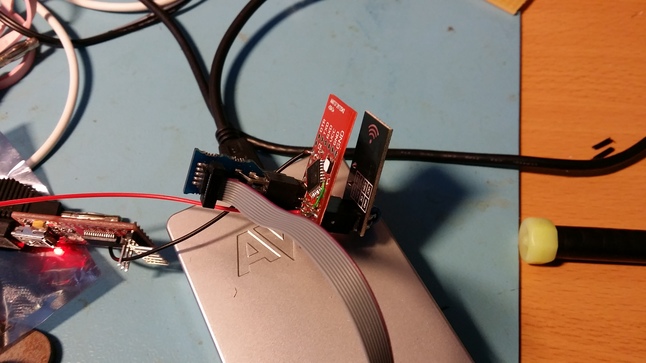
And today, radio connection verified, and Si7021 communication is up and running..
Only problem though, is that the Si7021 reports a temperature of 45-50 degrees celcius, where I know it should be closer to 22 degrees..
Also current consumption is rather high at the moment, arround 40mA, It feels like the SI7021 is getting a little bit warmer, than the rest of the components, which (to me) indicates that there is something wrong here.. I accidentially supplied the board with 5V for at test of the internal RC oscilator stability, which is way above the maximum supply voltage of 3.6V. So that might have killed it.
-
@ServiceXp
In the "lab" at the moment, testing the first prototype build.. I got the humidity / temperature "bug" sorted out. Replaced the Si7021 chip on my board, and the new one responded as expected, at least with correct temperature. (humidity is a bit off, I think.. I don't have another humidity sensor at hand here in the lab, so can't compare it..)
I also got the radio up. I haven't done any distance measurements yet, but I can reach the gw in the main building (6-7m away throug a couple of brick walls). Added a 2.2uF cap to the radio. It's still running off the bench power supply. I don't see any problems at the atmel side of things when radio is transmitting.
I just made a test, supplying the setup with 1.9V, and the GW still received the temperature updates :) (somehow my humidity readings don't get through to pidome on the GW, so have to check my setsup again).
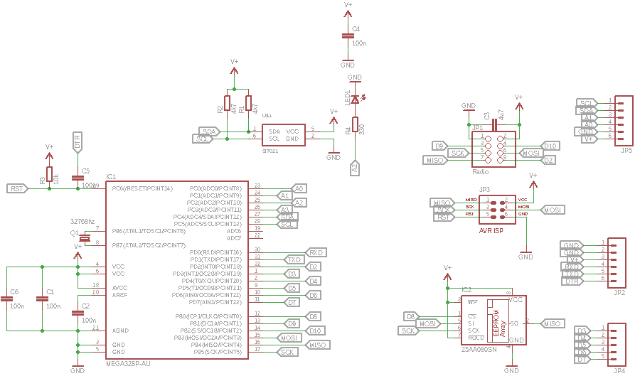
I'm waiting for a peer review of the pcb layout, before I push the button for the next batch of proto pcb's. btw. on the next prototype build, I have removed the bmp180, but exposed the SDA/SCL pins on a connector, so it can be attached externally..
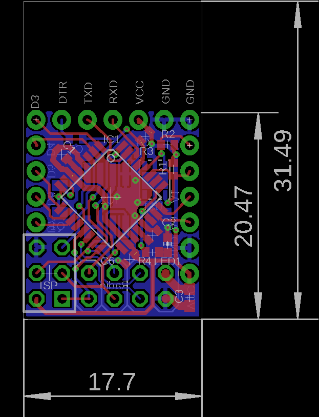
And here is a small preview of the upcomming board prototype.. I had to make the board 1.5mm wider, to make it fit a multiple of 0.1mil between the pinheaders on each side of the pcb. So it will be more versatile to other people as well.. (if any one should want to build them)
-
small update again
Did a small rangetest, and it seems that the range is equal to my other sensor (based on arduino mini and batteries). Also moved the node to the main builidng, besides the weatherstation that I got for christmas (which have hygrometer buildin). It seems that the humidity level on both my sensor node, and the weatherstation is almost comparable.
-
@ServiceXp
Haven't tested the eeprom yet, as I don't have any use for it right now. And also need to verify the 32khz crystal oscillator (currently running on the internal rc oscillator). Come to think about it, I need to think up some scenarios where the crystal could come in handy.
Investigations are undergoing, to make something for the "public". Can't say anymore at the moment :)
-
hmm.. Now I've had the two sensors on the table beside each other (sensor #1 and #2).
Temperature is off by 1.6 degrees celcius, and humidity 2% difference. Could be it's the different temperature, that makes the RH calculation differ a bit..
And for some build data.. It took me a good hour to populate all the parts. This one also have the additional eeprom mounted. but still need something for verifying that it works..
-
@ServiceXp
according to the datasheet the precision on temperature is +/- 0.4 degrees celcius, and +/- 3% RH.
They did however release a new chip revision (Si7021-A20) just after I bought mine (which is A10), they had some problems where the chip didn't enter standby correctly. Maybe that is the problem (also battery drain has been quicker than what I expected on the new node)
and yes, it's about an hour handsoldering things, and also programming the sensor, which also caused some troubles. Had to reprogram a lot of times, because of checksum errors. This could be caused by the fact that I have both eeprom, and nrf24l chip hanging on the SPI bus on the atmega, this is the same bus that is used by my ISP programmer (jtag ice3).
Think I have to get a proper bootloader into the device, so I can use the serialport to download instead.
-
and now the external SPI flash is verified as working, just with a simple program, reading out the manufacturer ID, and writing / reading data to/from the device.
Next step I wanted to get a bootloader working, so I could use standard arduino to download firmware, and also (at some point in time) utilize the flash for OTA updates. However, I can't seem to get bootloader support working..
I have tried to get DualOptiboot from lowpowerlabs working now, with several rebuilds etc., it seems like it is running fine (LED is blinking a couple of times, when it boots) but arduino wont sync to the bootloader, so either it runs on a wrong baudrate, or something else is wrong in the setup. But so far I haven't suceeded in figuring out what it is..
(Anyone else that has some knowledge on bootloaders, that could have an idea to what to look at?)
/ Thomas
-
I am almost ready for a second prototype spin of the PCB, but before doing that I could use some input from the community,
If this board was going into "mass production", is there any features that I should consider adding? Any missing parts? Anything that you think that I have forgotten?
The schematics for revision 2 is a couple of posts back in the thread.
I have considered adding a ATSHA204 for future security purposes, but can't seem to find a suitable spot for it (maybe I'm just too tired to see things clearly at the moment :)).
-
and now the external SPI flash is verified as working, just with a simple program, reading out the manufacturer ID, and writing / reading data to/from the device.
Next step I wanted to get a bootloader working, so I could use standard arduino to download firmware, and also (at some point in time) utilize the flash for OTA updates. However, I can't seem to get bootloader support working..
I have tried to get DualOptiboot from lowpowerlabs working now, with several rebuilds etc., it seems like it is running fine (LED is blinking a couple of times, when it boots) but arduino wont sync to the bootloader, so either it runs on a wrong baudrate, or something else is wrong in the setup. But so far I haven't suceeded in figuring out what it is..
(Anyone else that has some knowledge on bootloaders, that could have an idea to what to look at?)
/ Thomas
-
@boozz said:
@tbowmo
Does this link help you? Some explanation on bootloaders and practical stuff to help you burn botloaders on the ao Atmega326...BR
BoozzI can program a standard arduino bootloader, which works. I just want to use the one from lowpowerlabs, dual optiboot, so i can utilise the external Flash chip. But i Can't get it to work at all.
-
I am almost ready for a second prototype spin of the PCB, but before doing that I could use some input from the community,
If this board was going into "mass production", is there any features that I should consider adding? Any missing parts? Anything that you think that I have forgotten?
The schematics for revision 2 is a couple of posts back in the thread.
I have considered adding a ATSHA204 for future security purposes, but can't seem to find a suitable spot for it (maybe I'm just too tired to see things clearly at the moment :)).
@tbowmo said:
I am almost ready for a second prototype spin of the PCB, but before doing that I could use some input from the community,
If this board was going into "mass production", is there any features that I should consider adding? Any missing parts? Anything that you think that I have forgotten?
The schematics for revision 2 is a couple of posts back in the thread.
I have considered adding a ATSHA204 for future security purposes, but can't seem to find a suitable spot for it (maybe I'm just too tired to see things clearly at the moment :)).
I would work on trying to get the ATSHA204 included, even if it means the dims get a little larger. The one thing that I really don't like about MySensors is the lack of any wireless security.. Would love to see this implemented.
-
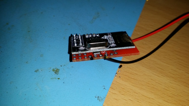
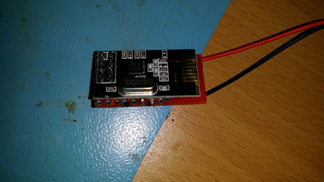
And sensor #2 is build.. This time the radio module is soldered directly to the sensor module, making it a realy small device now..
-
@tbowmo Maybe i missed it but do you have an image with the si7021 attached to the radio and pcb?
-
@tbowmo said:
I am almost ready for a second prototype spin of the PCB, but before doing that I could use some input from the community,
If this board was going into "mass production", is there any features that I should consider adding? Any missing parts? Anything that you think that I have forgotten?
The schematics for revision 2 is a couple of posts back in the thread.
I have considered adding a ATSHA204 for future security purposes, but can't seem to find a suitable spot for it (maybe I'm just too tired to see things clearly at the moment :)).
I would work on trying to get the ATSHA204 included, even if it means the dims get a little larger. The one thing that I really don't like about MySensors is the lack of any wireless security.. Would love to see this implemented.
@ServiceXp said:
I would work on trying to get the ATSHA204 included, even if it means the dims get a little larger. The one thing that I really don't like about MySensors is the lack of any wireless security.. Would love to see this implemented.
For one second, I thought you where danish :), as the word "dims" usually refers to a small gadget like device, that you don't have a name for at the moment (or even components, screws, bolts, anything small could be a "dims") :)