Minimal design thoughts
-
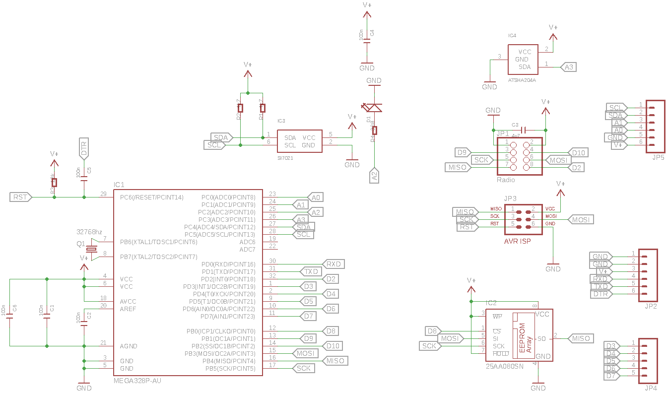
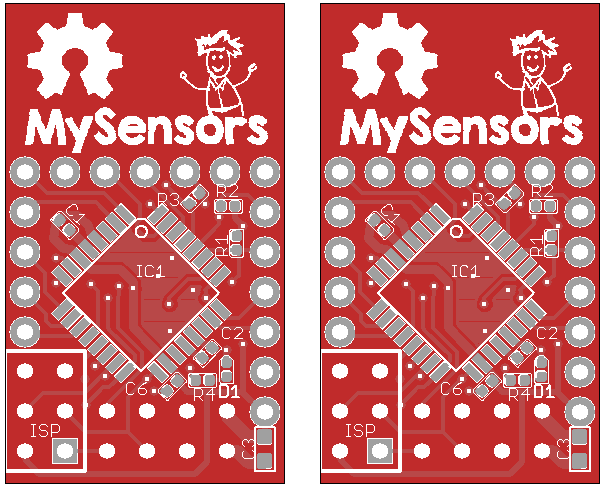
It's single wire atsha204, it's connected to A3. I couldn't fit in the 8 pin variants of the atsha204, so that ruled out the full I2C bus version. It even took me a couple of hours of re-routing to make enough room for the sot23 housing of the ATSHA204.
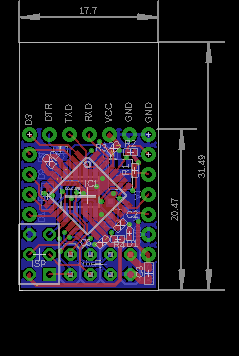
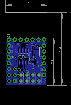
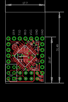
Anyway, schematic / pcb layouts are as follows
-
It's single wire atsha204, it's connected to A3. I couldn't fit in the 8 pin variants of the atsha204, so that ruled out the full I2C bus version. It even took me a couple of hours of re-routing to make enough room for the sot23 housing of the ATSHA204.
Anyway, schematic / pcb layouts are as follows
-
I wonder what kind of "hit" on battery life authentication/encryption will have?
-
I do not think it is a big issue. Authentication is normally only needed on nodes that have actuators. And this implies that they always have to listen for incoming data and are therefore inherently non-battery friendly The ATSHA has a very low power consumption, so the added cost for message signing procedures is probably negligible compared to the cost of running the radio continuously.
-
Hmm thinking about it, authentication could be valuable on sensors as well.
If you use the sensor readings to control another actuator, then an attacker could send in his own bogus sensor values in order to trigger system events. He does need to know the specifics about your setup though, so the question is if it's affordable to the mischief to do anything like that :)
-
Yep. This is true, and something I eventually have to add support for.
-
@Dirk_H said:
@tbowmo I don't see a Load Capacitor on the crystal. Especially if you need a precise clock you should use some. Have a look at https://www.adafruit.com/blog/2012/01/24/choosing-the-right-crystal-and-caps-for-your-design/ for example about Load Capacitors.
I know that normally the crystal require load capacitors, but for the low freq. oscilator (32Khz) its not necessary (as far as I have read), that's why I omitted them from the design. I'll try and dig out the datasheets when I'm at home and double check things.
@tbowmo said:
@Dirk_H said:
@tbowmo I don't see a Load Capacitor on the crystal. Especially if you need a precise clock you should use some. Have a look at https://www.adafruit.com/blog/2012/01/24/choosing-the-right-crystal-and-caps-for-your-design/ for example about Load Capacitors.
I know that normally the crystal require load capacitors, but for the low freq. oscilator (32Khz) its not necessary (as far as I have read), that's why I omitted them from the design. I'll try and dig out the datasheets when I'm at home and double check things.
Got around to check up on datasheet for atmel328p, when using lowfrequency oscilator, it has internal load capacitors. If you look at page 33 in the datasheet. So it's not necessary for external capacitors
-
And pcb's are ordered.. Again, using dirtypcbs.com, for the order..
I have used a panelizer tool from http://blog.thisisnotrocketscience.nl/ to panelize the boards this time, so it should be easier to depanelize it when they get here..
-
And pcb's are ordered.. Again, using dirtypcbs.com, for the order..
I have used a panelizer tool from http://blog.thisisnotrocketscience.nl/ to panelize the boards this time, so it should be easier to depanelize it when they get here..
@tbowmo Looks great!
Haven't actually ordered anything produced by the panelizer yet, but the results look really amazing:
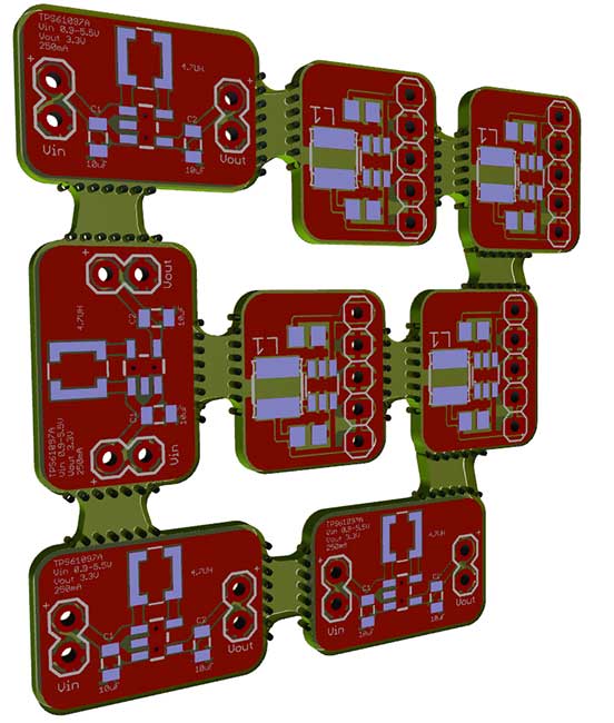
I was planning to finally get around to some boost regulators. But I need to design mine from scratch (these are just scavenged from other places) so they follow the same design guide lines and can be plugged in seamlessly to the main pcb.
Would be great if there were some sort of common design to follow for designing shields and such.
-
As you all probably have noticed, there is an mysensor logo on the boards, that I just ordered.. :)
I have been cooperating with @hek for a while, and this is going to be an "official Mysensor pcb" :)
We have been in discussions with a vendor in china, for doing SMT assembly as well.. We are currently waiting for the pcb's to arrive and get them populated, to verify that everything is as it should be, before we start up production in China.
For a batch of 100 units, the price is about 13$ per unit, plus shipping/handling fee, this is without any profits to the project
One question though, I made room for an ATSHA204 chip on the board, that could be used for authentication purposes, we want to know if this should be mounted as default on the board, as it will add arround 1$ to the unit price.
Also how many would be interested in ordering one (or 10, 20, 50?) of them? :) (just so that we get an indication if we should make a batch of 100 units, or 500 units)
That's 2 questions... :-)
- Yes, It's worth it to me (Hopefully there will be MySensors software support down the road)
- I would probably start off with 3 to 5.
Will there be a "kit" price for those who want to populate and reflow themselves?
-
As you all probably have noticed, there is an mysensor logo on the boards, that I just ordered.. :)
I have been cooperating with @hek for a while, and this is going to be an "official Mysensor pcb" :)
We have been in discussions with a vendor in china, for doing SMT assembly as well.. We are currently waiting for the pcb's to arrive and get them populated, to verify that everything is as it should be, before we start up production in China.
For a batch of 100 units, the price is about 13$ per unit, plus shipping/handling fee, this is without any profits to the project
One question though, I made room for an ATSHA204 chip on the board, that could be used for authentication purposes, we want to know if this should be mounted as default on the board, as it will add arround 1$ to the unit price.
Also how many would be interested in ordering one (or 10, 20, 50?) of them? :) (just so that we get an indication if we should make a batch of 100 units, or 500 units)
-
That's 2 questions... :-)
- Yes, It's worth it to me (Hopefully there will be MySensors software support down the road)
- I would probably start off with 3 to 5.
Will there be a "kit" price for those who want to populate and reflow themselves?
@ServiceXp said:
That's 2 questions... :-)
I edited it a couple of times while talking with @hek last evening, so it slipped. Hope you can forgive me ;)
- Yes, It's worth it to me (Hopefully there will be MySensors software support down the road)
- I would probably start off with 3 to 5.
Will there be a "kit" price for those who want to populate and reflow themselves?
No kit version, the pcb will be released under oshw so you could order it yourself, and source the components. However my unit price for the initial units will hit 11-12$, so it's only 1 or 2$ extra to get it smt assembled in China.
The more units we can order the cheaper it will become.
-
@ServiceXp said:
That's 2 questions... :-)
I edited it a couple of times while talking with @hek last evening, so it slipped. Hope you can forgive me ;)
- Yes, It's worth it to me (Hopefully there will be MySensors software support down the road)
- I would probably start off with 3 to 5.
Will there be a "kit" price for those who want to populate and reflow themselves?
No kit version, the pcb will be released under oshw so you could order it yourself, and source the components. However my unit price for the initial units will hit 11-12$, so it's only 1 or 2$ extra to get it smt assembled in China.
The more units we can order the cheaper it will become.
@tbowmo I might be interested in a few, seeing as this PCB has some pretty unique features, but I'm still in the market for a board with an on-board regulator that will give me a bit more flexibility.
The problem (for me) is that while waiting for any official hardware, I've bought a lot of other stuff. I had another 10x Arduino Pro Mini arrive just yesterday for instance. Plus the booster project above. I ordered a couple of hundred brand inductors and capacitors as well as ltc3525 ICs. So basically now I don't have a choice but to go it alone for the most part :sweat:
What we could need right now is some clear direction, like whether the ATSHA204 is the way to go. Or some common form factor that would allow future shields or whatnot.
Also, for something really small like this, to be put into production, I would have liked to have tried with the "smd / mini nrf24" version that is also available on Ebay, just to keep the size down even further. I just got three of those yesterday and they are indeed very tiny (pin header spacing is 1.27mm). Whether they work ok or not I do not know. I do know that some people on the forum have posted project pictures with these mini nrf24. I guess what I'm saying is that lowpowerlabs already invented the wheel here: http://lowpowerlab.com/moteino/
Would be great to hang a mini nrf24 flat off of the back if at all possible. But given what we know of the nrf24 it would probably blow up in our faces compared to the RFM12B/RFM69 that the moteino uses. Of course, they also use a wire antenna while we still trust the pcb antenna ... -
@tbowmo I might be interested in a few, seeing as this PCB has some pretty unique features, but I'm still in the market for a board with an on-board regulator that will give me a bit more flexibility.
The problem (for me) is that while waiting for any official hardware, I've bought a lot of other stuff. I had another 10x Arduino Pro Mini arrive just yesterday for instance. Plus the booster project above. I ordered a couple of hundred brand inductors and capacitors as well as ltc3525 ICs. So basically now I don't have a choice but to go it alone for the most part :sweat:
What we could need right now is some clear direction, like whether the ATSHA204 is the way to go. Or some common form factor that would allow future shields or whatnot.
Also, for something really small like this, to be put into production, I would have liked to have tried with the "smd / mini nrf24" version that is also available on Ebay, just to keep the size down even further. I just got three of those yesterday and they are indeed very tiny (pin header spacing is 1.27mm). Whether they work ok or not I do not know. I do know that some people on the forum have posted project pictures with these mini nrf24. I guess what I'm saying is that lowpowerlabs already invented the wheel here: http://lowpowerlab.com/moteino/
Would be great to hang a mini nrf24 flat off of the back if at all possible. But given what we know of the nrf24 it would probably blow up in our faces compared to the RFM12B/RFM69 that the moteino uses. Of course, they also use a wire antenna while we still trust the pcb antenna ...@bjornhallberg said:
@tbowmo I might be interested in a few, seeing as this PCB has some pretty unique features, but I'm still in the market for a board with an on-board regulator that will give me a bit more flexibility.
The problem (for me) is that while waiting for any official hardware, I've bought a lot of other stuff. I had another 10x Arduino Pro Mini arrive just yesterday for instance. Plus the booster project above. I ordered a couple of hundred brand inductors and capacitors as well as ltc3525 ICs. So basically now I don't have a choice but to go it alone for the most part :sweat:
What we could need right now is some clear direction, like whether the ATSHA204 is the way to go. Or some common form factor that would allow future shields or whatnot.
Also, for something really small like this, to be put into production, I would have liked to have tried with the "smd / mini nrf24" version that is also available on Ebay, just to keep the size down even further. I just got three of those yesterday and they are indeed very tiny (pin header spacing is 1.27mm). Whether they work ok or not I do not know. I do know that some people on the forum have posted project pictures with these mini nrf24. I guess what I'm saying is that lowpowerlabs already invented the wheel here: http://lowpowerlab.com/moteino/
Would be great to hang a mini nrf24 flat off of the back if at all possible. But given what we know of the nrf24 it would probably blow up in our faces compared to the RFM12B/RFM69 that the moteino uses. Of course, they also use a wire antenna while we still trust the pcb antenna ...I forgot about the mini nrf24 modules. But I don't think that we could have squeezed it that much more in size, we could probably save 2-3mm in stack height, but that's about it.
Also, this board was designed from the beginning to be a battery operated node. That is why there is no regulator on board (besides the fact that there is no room for it). I selected the components for their ability to work on low voltages all, except the atsha204, is able to work on a VCC as low as 1.8V)
I have seen lot's of questions asking about battery operation of 3.3V arduino mini pro, with DHT22 sensors attached. People cut LED's and regulators on the arduino, in order to get the power consumption as low as possible. This is where this particular board fits in. It's ready for battery operation, and has the temperature / humidity sensor build in.
It started out because I wanted an "easy" clean option for sensor nodes for my own application, without any wire nests between arduino and nrf24 modules. I hope that it will be useful for others as well, and might be able to get others going with the mysensor project.
For my own part, I could use up to 20 of these, for measuring temperature / humidity in every room in the house (and out side as well)
Btw. all those arduinos you've bought, could be turned into something else :)
-
I snapped some pictures just so everyone can see the difference between the nrf24 modules.
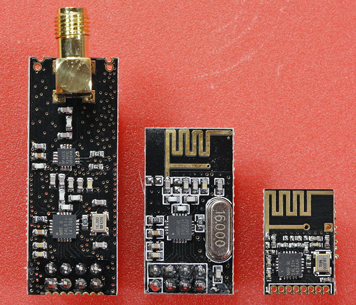
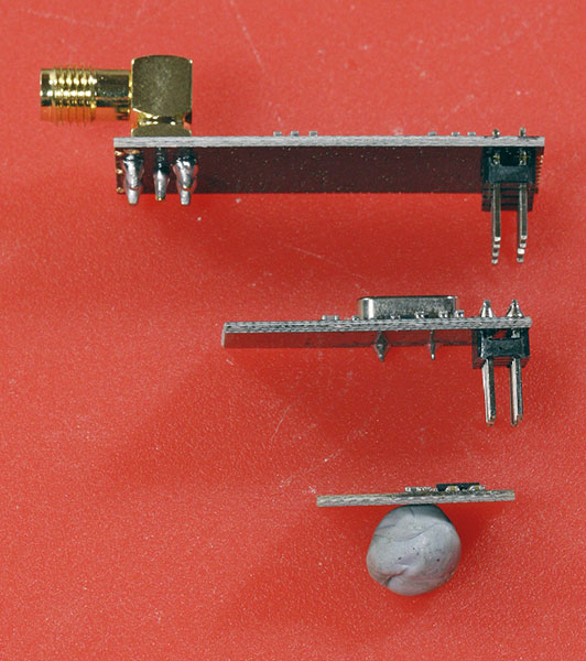
Of course, like I said, I don't even know if the "mini" works in a satisfactory manner. I'm gonna get some smaller pitch headers so I can make a prototype. But the PCB antenna actually seems to be the exact same size so I have high hopes for that aspect at least. -
The antenna still needs to hang over "free air" (or an unrouted PCB area), this is the area where the logo is located on the current design. It could be moved to the opposite end of the pcb (where the nrf24 pinheader is located).
If we switch to the mini module, then the pinheader for the radio is removed, but then you need a "larger" area where there is no components at all, in order to mount the nrf module flat to the sensor pcb. So in theory it will not be that much smaller, only the pinheader distance between the two pcbs can be removed.. lenght /width will be almost the same, maybe a bit longer as there is not that much room to give, with the current number of components (Si7021, eeprom, atsha204 etc).