Powering mote 24/7 using only a supercap and solar
-
i read this one too. his next article is http://www.limpkin.fr/index.php?post/2012/03/20/Indoor-solar-energy-harvesting%3A-3-months-data
and i studied this one http://www.ti.com.cn/cn/lit/ug/tidub22b/tidub22b.pdf when i did my choice about overall cost, if i wanted reliable delivery and signing packet, for my multisensors..so i thought that would add too much overhead on my specific device (cost) but this chip is very nice for simple, low power BLE like, short burst ;)Thanks for the articles, guys.
The TI article takes the approach of running off a battery when there's not enough solar. Although that feels a bit like cheating, it might be valid if used just to power an MCU rather than do a full cold start before that's possible. Another approach would be to use something like an LTC3108, which is a boost converter optimized to boost very, very low voltage/current values. Maybe that could power an MCU much more quickly than rely only on the cold start abilities of the BQ25504. Perhaps it would turn out that an LTC3108 would be sufficient, all by itself. I think it's worth exploring.
-
Also, a larger, higher voltage panel coupled with a buck-boost converter (https://www.openhardware.io/view/276/33v-Buck-Boost-DC-DC-Converter) might offer another solution, perhaps one that isn't so affected by cold start issues.
Of course, some might simply use a larger, higher voltage panel directly wired to the supercap, without any intermediating converter. I'm not sure how that compares in performance, but it does have the virtue of simplicity.
-
Jeelabs has some nice posts on startup power:
http://jeelabs.org/2013/03/29/jeenode-micro-start-up-power/index.html
http://jeelabs.org/2012/12/29/rfm12b-startup-power-consumption/index.html
http://jeelabs.org/2012/09/09/delayed-power-up/index.html
http://jeelabs.org/2012/05/29/its-about-survival/index.html -
I built the pass-through boost converter (https://www.openhardware.io/view/285), and it works. :) However, for use with a small, low voltage solar cell, it has a cold-start problem: in order to enable the boost converter, the SHDN pin must be held high by continuously applying at least 1 volt to it.
-
@NeverDie would the mosfet solution suggested in the delayed power-up post from jeelabs work?
@mfalkvidd
I guess you're seeing something that I don't, because I don't see how it relates. -
@mfalkvidd
I guess you're seeing something that I don't, because I don't see how it relates. -
@mfalkvidd
Aw gee, I was hoping you saw something in it that was blindingly obvious that I was, uh, blind to. In fact, I'm still hoping that. :)jcw is a really good author. Too bad that lately he has gone off the deep end into FORTH and the like rather than exploring solar energy like he should be. LOL. Then maybe I wouldn't have to be doing it. Surely someone out there has figured out this topic already. I mean, solar calculators have been around for decades, and they have tiny solar cells. Maybe I should use one of those solar cells? Now it has me wondering what voltage solar calculator cells produce.
-
Moving on, I built a different boost converter using the LTC3525-3.3 (not the LTC3525D-3.3, as previously, which was the bypass version of the chip).
The LTC3525-3.3 is, I think, a better choice than the D version, because when the voltage on SHDN falls below 0.4v, it disconnects itself from the output. That means the supercap won't drain itself to zero by draining current backwards through the boost converter. When the voltage on SHDN is greater than 1.0v, then the chip is reconnected to the output (a supercap in our case). What happens when the voltage on SHDN is between 0.4v and 1.0v? Good question. That's undefined.
-
I put together my buck-boost project (https://www.openhardware.io/view/276/33v-Buck-Boost-DC-DC-Converter), and it works. I thought that if I were to charge a supercap (or series of supercaps) to a higher voltage (say 5v), it might be a good way to use the stored energy. At the moment, though, I don't think that's the near-term direction this solar project is heading.
I assembled and tested the cheapest of the boost converters (https://www.openhardware.io/view/278). It works. Ironically, because it lacks an enable pin, one could argue that it actually has less of a cold start problem than its more expensive counterparts. Its startup voltage is 0.8v, and after that it can drop to 0.5v (where it draws about 12ma of current in a no load scenario). For weak indoor lighting, its current demands are too high for a small solar cell. However, in direct sunlight, it could definitely provide 3.3v.
-
Good news! I jerry rigged one of the above mentioned load switches inline with the BQ25504, and Lo! It can sustain a lightly loaded voltage of 3.1v output all the way down to an input voltage of 0.21v before collapsing.
So, I hooked up my el cheapo solar cell, and I confirmed that it does the business even in ambient light. :)
-
So, I've revised my BQ25504 PCB to include the load switch, and I've sent the files off to the fab.
-
The next thing I need to look into is how to measure voltages and currents in the least disruptive way. Using a multimeter to measure the voltage on a cap can noticeably affect the voltage, due to current drain. One option would be to use the ADC on an atmega328p. Another would be to use an INA219. I think one of the keys will be to switch on for the measurement and then switch off as quickly as possible, as opposed to a multimeter which stays switched on until you manually switch it off.
If anyone has any other suggestions for minimally disruptive measurements, please do post.
-
Translating the above programmed voltages into resistor values that can be purchased on Digikey yields the following:
ROV1 = 5.1M
ROV2 = 4.7M
ROK1 = 6.2M
ROK2 = 3.3M
ROK3 = 510K
RUV1 = 10M
RUV2 = 0 or 1 ohm (doesn't matter which)@NeverDie said:
Translating the above programmed voltages into resistor values that can be purchased on Digikey yields the following:
ROV1 = 5.1M
ROV2 = 4.7M
ROK1 = 6.2M
ROK2 = 3.3M
ROK3 = 510K
RUV1 = 10M
RUV2 = 0 or 1 ohm (doesn't matter which)I built a bq25504 pcb using these values, and it tested out correctly.
-
I found that this guy had a similar goal as me (in his words, "I envisioned several electronic projects that would charge a capacitor during daylight using a solar panel, and then consume that energy to stay awake at night") and has done an interesting write-up not only on how to do non-disruptive capacitor voltage measurements, but also how to reduce capacitor self-discharge (e.g. even "no clean" flux residue can significantly increase self-discharge of capacitors and should be removed). To make non-disruptive voltage measurements for monitoring/debugging of prototypes, he uses Microchip MCP6S22 to create a high impedance buffer with 10 trillion ohms of input impedance.
-
This article gives a bit more detail on the brass tacks of how to actually use the mcp6s26: http://hackaday.com/2009/03/30/parts-programmable-gain-amplifier-mcp6s26/
I just now ordered some mcp6s26 from Digikey so I can try them out.
-
I suppose if worse came to worst, we could try answering the question empirically by using a test setup similar to this:
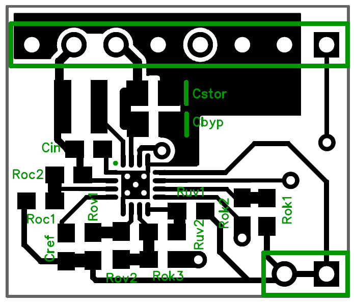
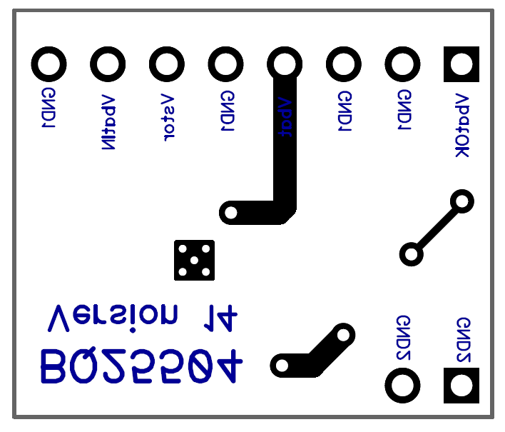
In this instance I partitioned the data ground from the power ground, and the two are not connected. However, via the header pins, a jumper could be connected between the two grounds. The experiment would be to try it both ways--connected vs. unconnected--and see which performs better.
@NeverDie said:
I suppose if worse came to worst, we could try answering the question empirically by using a test setup similar to this:
In this instance I partitioned the data ground from the power ground, and the two are not connected. However, via the header pins, a jumper could be connected between the two grounds. The experiment would be to try it both ways--connected vs. unconnected--and see which performs better.
By the way, I built this, and it unambiguously confirms that GND1 and GND2 need to be connected in order for the BQ25504 to work. If GND2 is left floating, it doesn't work.
-
I finally received the PCB breakout I made for the load switch. I put that together. Then I soldered together a prototype board to probe with an oscilliscope to see what's really going on with the BQ25504:
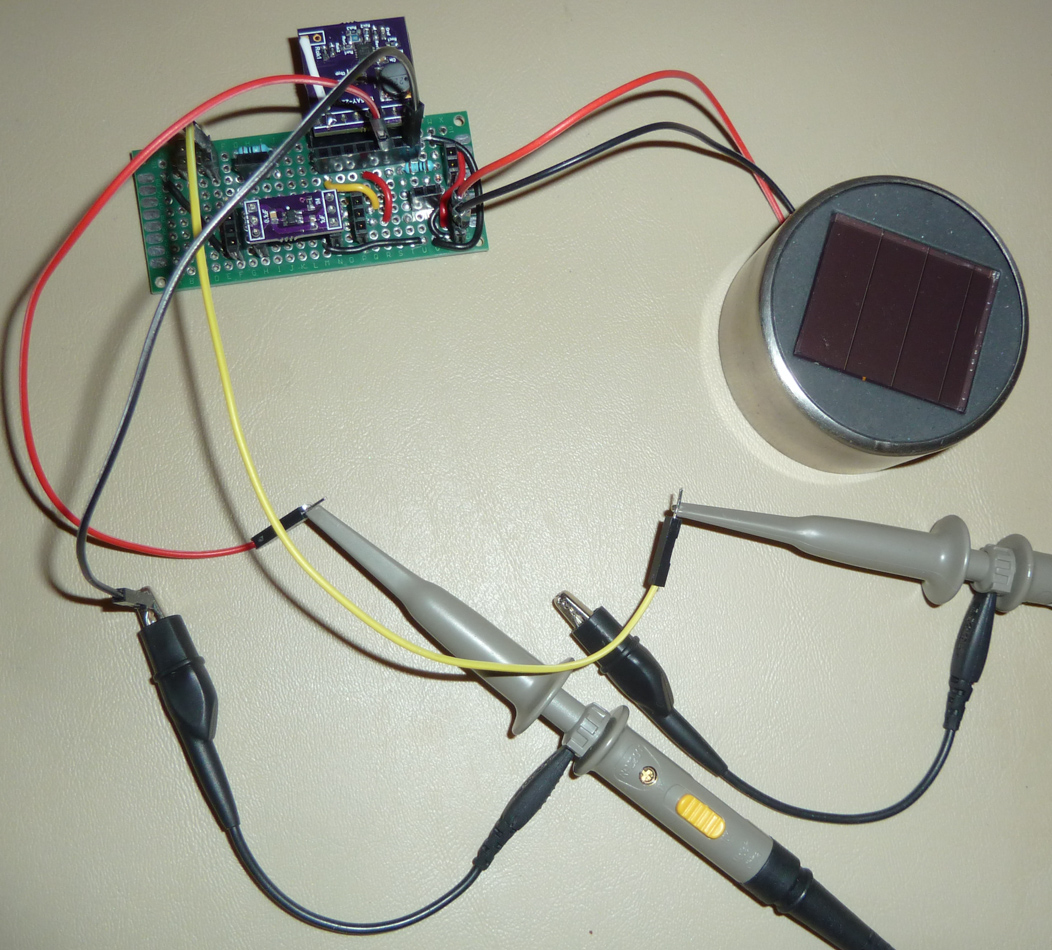
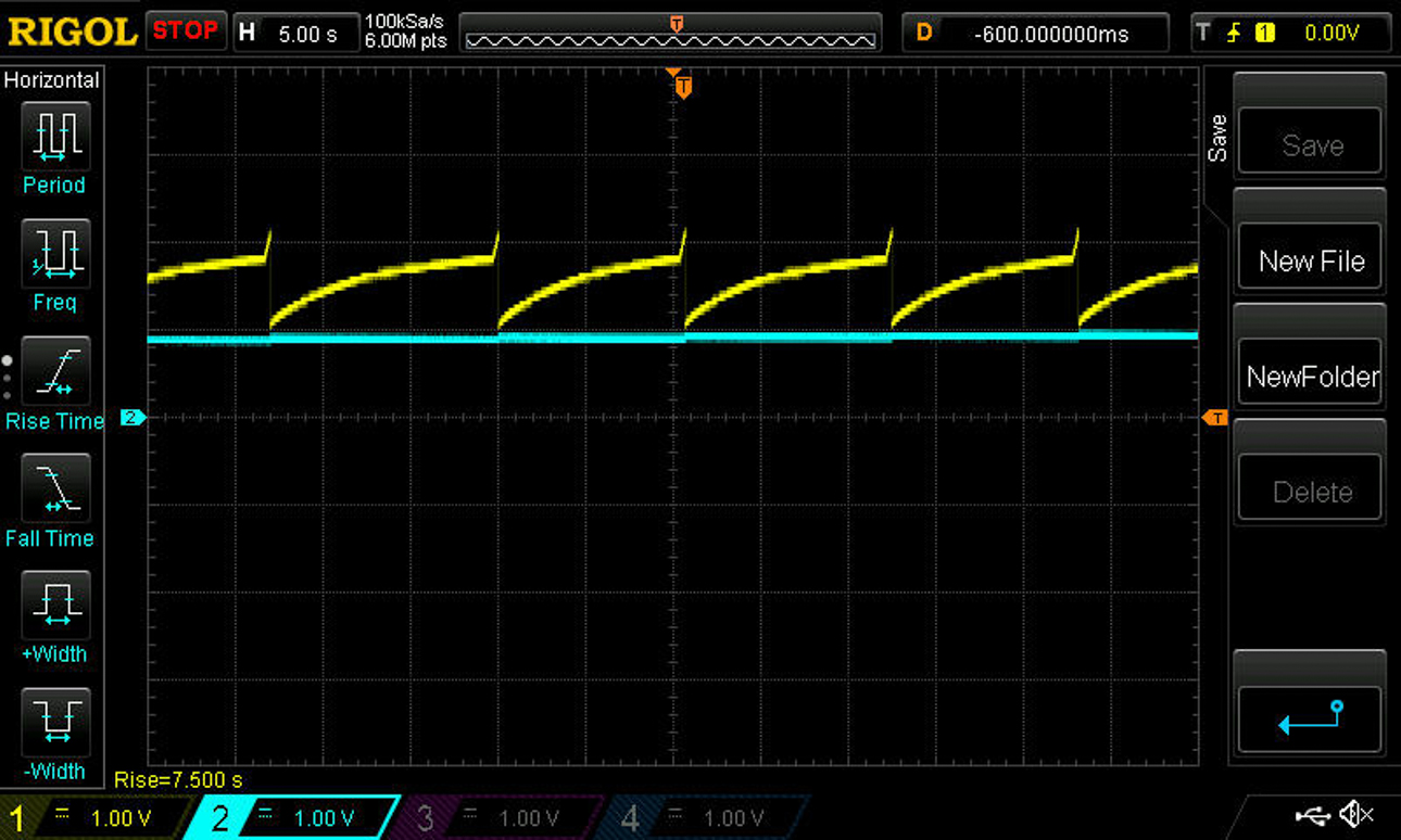
I soldered in a 300uF ceramic capacitor across VBAT and GND as the "battery". The datasheet recommends either a rechargeable battery or a minimum of 100uF.The first scope shot is with the 300uF nearly depleted. The blueline is the voltage across VBAT (i.e. the 300uF capacitor in this particular setup). The yellow line is the voltage on VSTOR on the BQ25504 breakout (about 4.7uF):
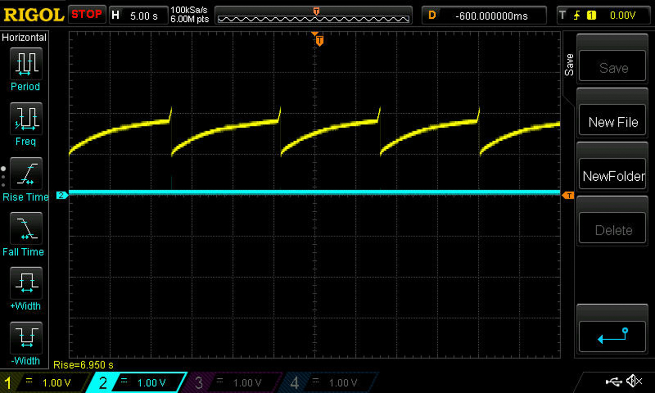
What you see is VSTOR being charged by the solar cell up to around 2 volts and then very briefly setting VBAT_OK to high, which turns on the load switch to discharge VSTOR into VBAT until VSTOR drops down to around 1 volt. Then it repeats. Notice that the voltage across VBAT doesn't climb very much in this screen shot. That's because we're in the cold start phase, and the conversion isn't MPPT but rather something else that's highly inefficient.Note: the amount of light landing on the solar cell is exactly the same across all the scope shots, because it's just a ceiling light in the room where I'm taking the measurements. Keep that in mind when you compare this first screen shot to the last one.
-
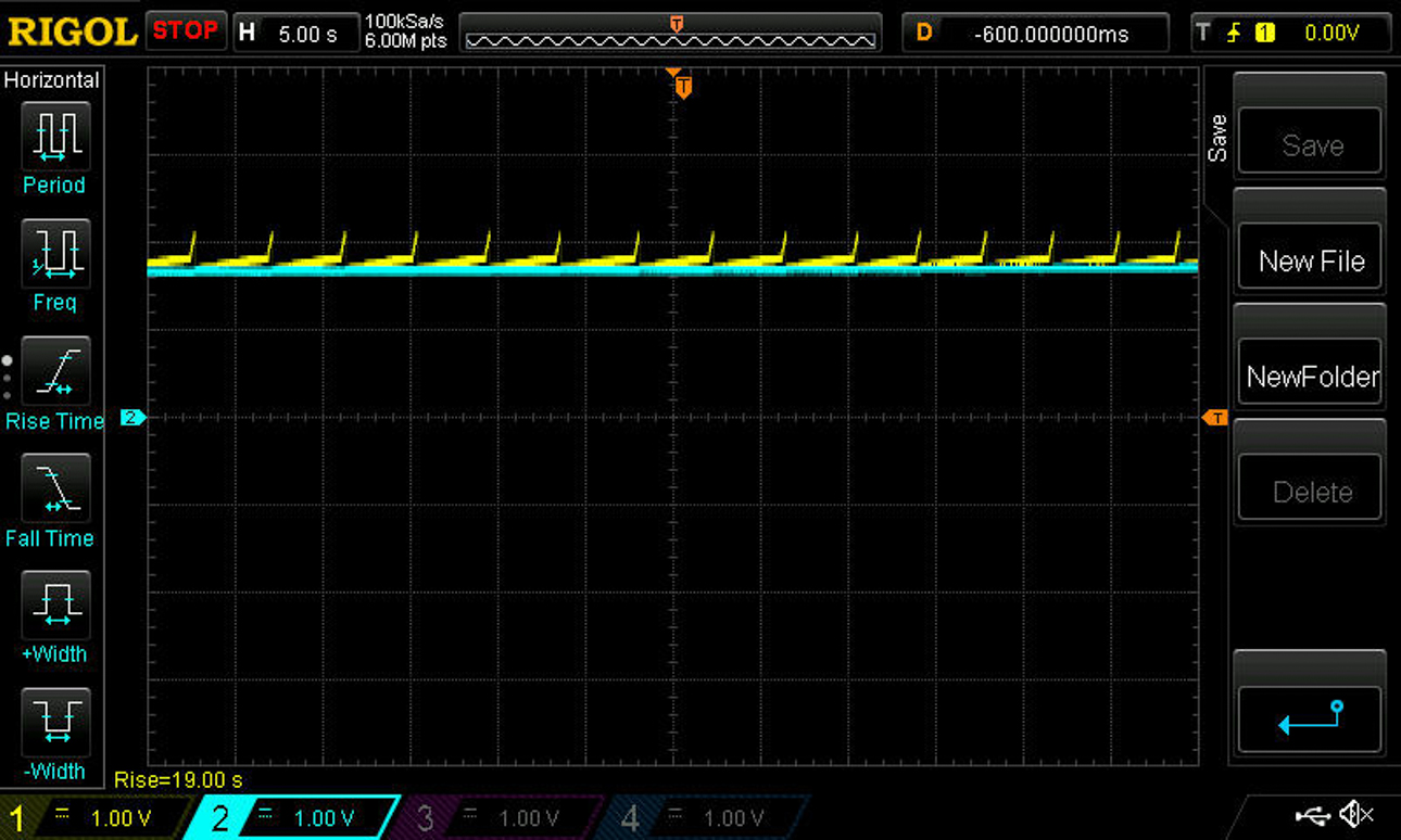
Later you can see that the voltage on VBAT has risen to 1 volt, and pretty much the same thing is going on:
Later still, the voltage on VBAT is about 1.6 volts, and again it's the same sort of thing. Notice that the voltage across VSTOR drops all the way to the voltage across VBAT, so as the voltage across VBAT increases, the period of the cycles becomes shorter:
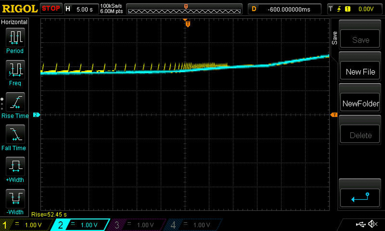
This next scope shot shows that as the voltage on VBAT rises to around 1.8 or 1.9v, a transition happens, and VBAT_OK stays turned on permanently. Notice how the rise in voltage after that really starts to accelerate. That's because at that transition, MPPT finally kicks in:
Lastly, here's anothe scope shot showing that after MPPT kicks in, the voltage rises a full volt in the same time period where previously (see preceding scope shots) hardly any voltage increase across VBAT was measured:
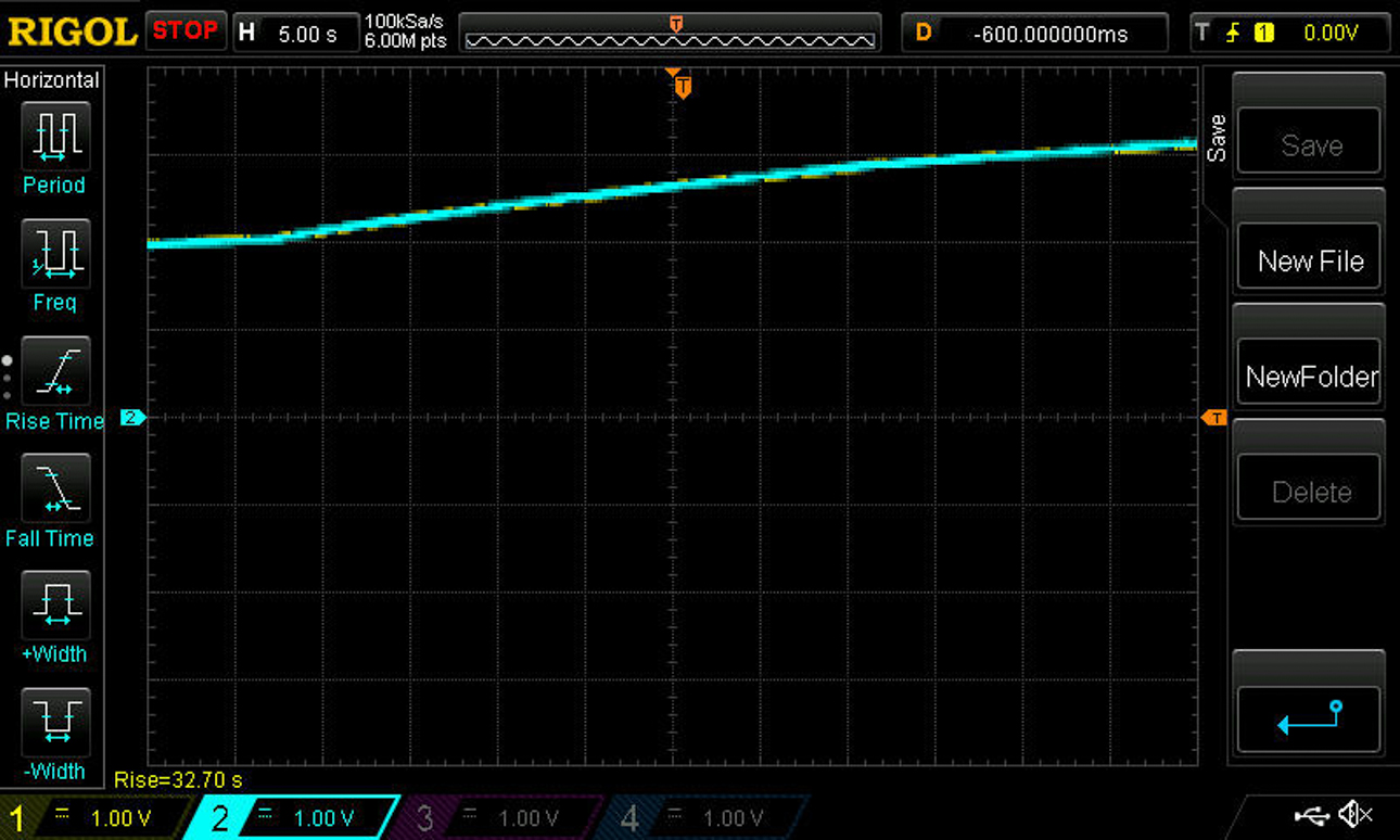
All of the above proves quantiatively how important it is to keep the voltage on VBAT above 1.8 volts, so that the BQ25504 chip can do an efficient job of harvesting the energy. As I mentioned earlier, the amount of light falling on the solar cell is exactly the same in all of the scope shots.