Powering mote 24/7 using only a supercap and solar
-
So, I decided to solder the 330uF cap to an mcp6s26, (see earlier post above for a description) which I had just recently received from Digikey:
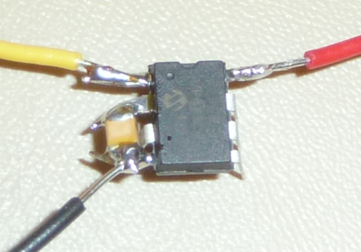
to see how that compares:
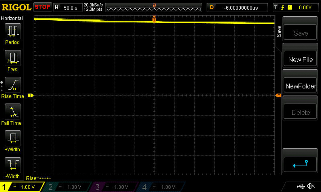
What's evident is that the rate of decline is less, and it seems to improve with time.
There is some decline still evident. How much of that is due to the capacitor and how much is do to ongoing measurement using the mcp6s26?
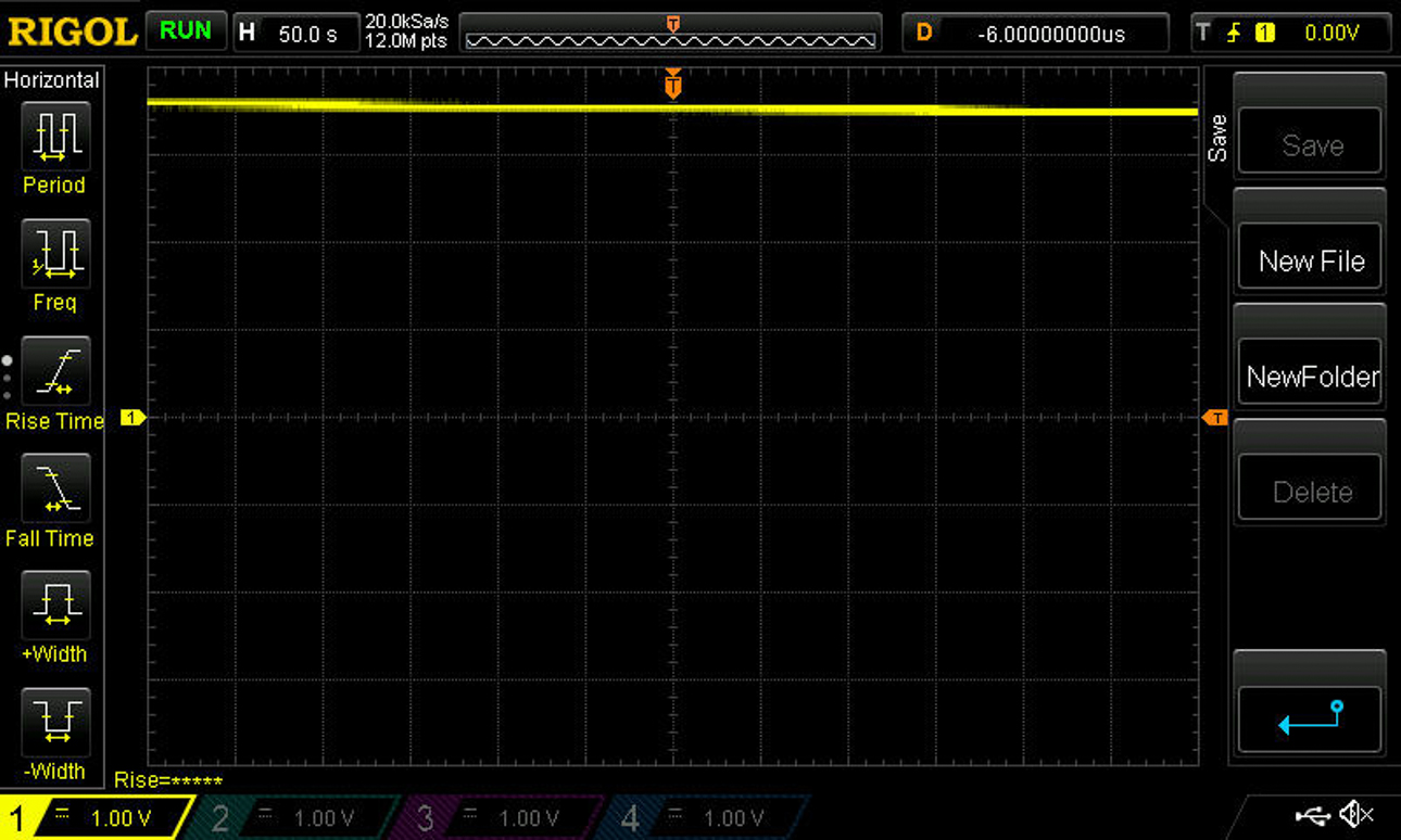
I kept the test running after the last post, and now, a bit more than four hours later, the scope shows:
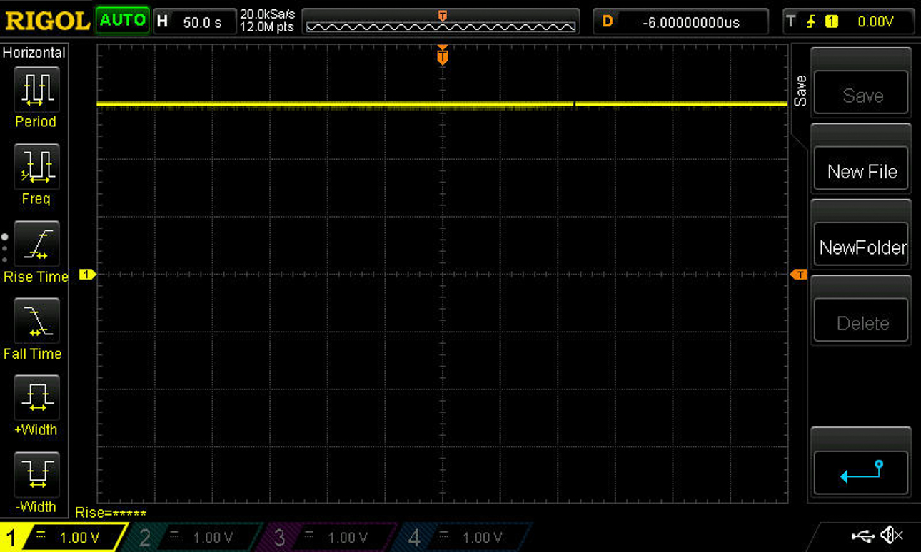
So, that's reason for optimism. I have to cut the measurements short tonight, but I'll try again tomorrow morning, when it can have more run time.
-
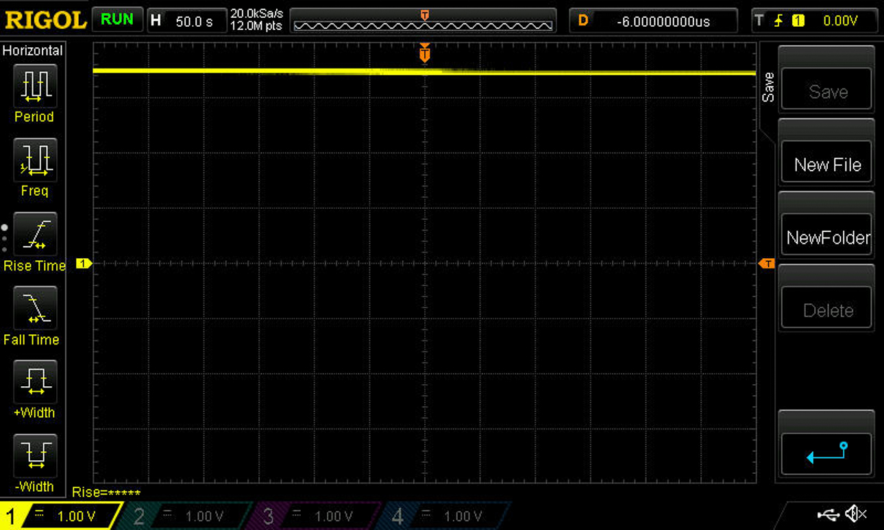
I kept the test running after the last post, and now, a bit more than four hours later, the scope shows:
So, that's reason for optimism. I have to cut the measurements short tonight, but I'll try again tomorrow morning, when it can have more run time.
-
Thanks for the suggestion. I decided to keep the above setup running through the night after all, and now, about 5 hours after the last screen shot, it's showing a voltage of about 2.8 volts. I'll let it continue to run and see how it goes.
Meanwhile, I ordered a shotgun assortment of different caps from Digikey. Unlike capacitors from Aliexpress, they'll have reputable datasheets. They'll have differing capacitance levels (220uF all the way up to 90F) so I can start to get a bearing on how much capacitance might be needed. Ideally I'd like to find something that could hold enough charge for a week or more, to handle worst case scenarios, but as yet I'm not sure that will be possible. For instance, if it turns out that 90F is what's needed, I'm not as yet sure if my el cheapo solar cell powered by ambient light could even charge it in a day. On the other hand, I'm quite sure it could easily charge a 330uF capacitor. So, with the new caps, I'll start gathering some data on how much charge can be realistically harvested as well.
The 220uF cap (http://www.digikey.sk/product-detail/en/NOJC227M006RWJ/478-8864-6-ND/4562183) will be interesting, because it's made from Niobium Oxide, which has low ESR and claims to have a leakage current of 14ua. Leakage current and self discharge rate are defined differently, but my hunch (?) is that they are strongly correlated (i.e. my WAG is that a cap with a low leakage rate will have a low self discharge rate also). That is to say: I'm hoping that leakage current might be a proxy for self discharge rate, because at least so far it has been easier to find info on leakage rates than self discharge rates.
-
@NeverDie Just a suggestion: keep the cap on charge during the night, since it seems they get better if they get tie to saturate.
@mfalkvidd said:
@NeverDie Just a suggestion: keep the cap on charge during the night, since it seems they get better if they get tie to saturate.
You're right! According to Maxell (http://www.maxwell.com/images/documents/1007239-EN_test_procedures_technote.pdf), the way leakage rates are measured is to first hold the capacitor at its rated voltage for 72 hours. For measuring self discharge, the cap is held at its rated voltage for just one hour, but then it is measured over the subsequent 72 hours.
On StackExchange, somebody asked, "How to calculate self-discharge time of capacitors given the leakage current?" (http://electronics.stackexchange.com/questions/35568/how-to-calculate-self-discharge-time-of-capacitors-given-the-leakage-current). There was only one answer, and its bottom line was: "the only way to be half-way sure about the self-discharge rates will be to build up a bunch of prototypes and test them." I'm surprised there's not a better way, but none was posted.
-
@mfalkvidd said:
@NeverDie Just a suggestion: keep the cap on charge during the night, since it seems they get better if they get tie to saturate.
You're right! According to Maxell (http://www.maxwell.com/images/documents/1007239-EN_test_procedures_technote.pdf), the way leakage rates are measured is to first hold the capacitor at its rated voltage for 72 hours. For measuring self discharge, the cap is held at its rated voltage for just one hour, but then it is measured over the subsequent 72 hours.
On StackExchange, somebody asked, "How to calculate self-discharge time of capacitors given the leakage current?" (http://electronics.stackexchange.com/questions/35568/how-to-calculate-self-discharge-time-of-capacitors-given-the-leakage-current). There was only one answer, and its bottom line was: "the only way to be half-way sure about the self-discharge rates will be to build up a bunch of prototypes and test them." I'm surprised there's not a better way, but none was posted.
@NeverDie the robot room link you provided earlier (to be precise, this post and this post) has more details, especially this part:
because there is no standard for testing self-discharge (how long to charge, when to start measuring current), it is difficult to compare different capacitors to determine which really has the lowest leakage for your project. -
The Maxell paper contradicts him in that regard. It says, "The test methods for leakage current and self-discharge are consistent industry wide. " That isn't to say, though, that the information for a particular capacitor is easy to find, however.
The capacitor that I've been testing is this one: https://www.digikey.com/product-detail/en/murata-electronics-north-america/GRM32ER60G337ME05L/490-13976-1-ND/6155806 It has been about 15 hours now since I started the test, and the voltage is presently at about 2.6 volts. So, as a first attempt, it's encouraging to see the capacitor maintaining a worthwhile voltage through the night until the next day.
-
By the way, it's worth mentioning that the mcp6s26 defaults to a gain of 1x on Channel 0. In my case I'm using exactly those defaults, which is convenient because I get the chip's benefits without needing to bother with SPI programming of the mcp6s26.
-
Maxim Integrated has a handy online calculator for estimating the super-capacitor capacity needed for RTC backups: https://www.maximintegrated.com/en/design/tools/calculators/product-design/supercap.cfm
I don't believe it accounts for self discharge, but maybe it at least helps estimate the right order of magnitude.
It has been close to 24 hours now, and the the voltage on the above test capacitor is now at 2.5 volts.
So, I think the next step is to hook one up to a sensor mote and see how long it can go--having the mote measure and report he capacitor voltage say every 5 minutes or so--before running out of juice.
-
I finally found some proper supercapacitor discharge curves (from page 15 of http://www.nec-tokin.com/english/product/pdf_dl/supercap_manual.pdf):
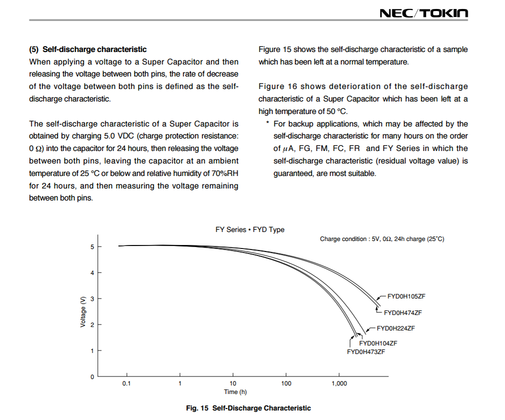
So, based on that, it looks like the FY Series of the NEC-Tokin supercaps is worth looking into. According to the chart, the best performing one is this one: http://www.digikey.com/scripts/DkSearch/dksus.dll?Detail&itemSeq=215649477&uq=636192387876420325
They sound well adapted to supplying voltage to a sleeping mote. Whether they can handle the current demands of an RFM69HW at maximum Tx, at least for a short burst, is unclear. If not, then perhaps it could be used to charge up a more conventional cap in advance of the burst current being needed.
-
Just now checked the voltage, and apparently it had dropped like a rock. Presently at 1.5v, and I've stopped measuring.
Based on this, it seems likely that 330uF won't be enough. My new WAG is that it will take a super capacitor that's somewhere in the 1F to 10F range to do the job with enough overkill to cover the worst case scenarios.
-
I notice that the above test procedure is different than Maxwell's (they pre-charge the capacitor for only 24 hours rather than the 72 that Maxwell uses), so maybe the robotroom guy (referenced above) was right about there being a lack of standards after all.
What's a bit annoying about charts like Figure 15 above is that they seem to present the best case scenario, rather than the "typical" or worst case scenario. Usually specifiers want to know the worst case, so they can pick a component that will cover that case. I guess what these charts do allow you to do (maybe) is choose among the best of the available product lines to build prototypes, and then from there you run your own tests for the typical or worst case. Of course, if Maxwell feels the need to pre-charge their capacitors for 72 hours, presumably (?) the Maxwell capacitors do substantially worse with "just" a 24 hour pre-charge. Meh, making comparisons is a mess.
So, I think that for the comparison tests that I will be doing, it will be better to not pre-charge the capacitors at all. Instead, I'll start the discharge test the moment they reach a charge of 3.6v, which is the highest I expect I would be charging them to. That should give a better approximation of the worst case performance, which is what I want to know. Depending on the relative freshness of the capacitors, that might unfairly handicap some of them, but so be it.
Any comments on this approach?
-
Also, for solar, I think it will make sense to charge the super cap to a lower voltage, because then the boost converter is more efficient if the solar cell voltage is low. That may mean a higher Farad supercap.
-
I've received the first traunch of capacitors from Digikey just now. I've decided to take a hybrid approach with respect to pre-charging. Since I don't want the voltage on the super cap to ever fall below 2.5v, I'm going to saturation charge it at that voltage. Then I'll see how much extra voltage the solar charge circuit can add to it in, say, 4 hours just from ambient room light in a room where the only source of light will be the ceiling light (so that the lux is controlled). Then, I'll either:
- Hook it up to a wireless mote and see how long it lasts until it drains to 2.5volts again, or
- watch the self-discharge on a scope again
Judging from the charge-up time of a 1F capacitor, I suspect 1F will be plenty. Ordinarily, more Farads would imply a higher self-discharge current, but in this solar charging scenario it will also mean that the accumulated voltage will stay closer to the saturated charge level, and so that might conceivably result in less self-discharge overall. I guess we'll see how it plays out.
-
The Vishay supercaps have a test procedure for self discharge that at least sounds plausibly achievable by a solar charger under real world conditions. Basically you charge the supercap to its rated voltage for one hour. Then disconnect the supercap and store it at room temperature for 24 hours. Then measure the voltage. According to the datasheet, the measured voltage after the 24 hours should be at least 90% of the rated voltage it was charged to (cf. page 13 of http://www.vishay.com/docs/28409/196hvc.pdf).
I'll be doing that test shortly on the 15F Vishay Supercap, which is one of the supercaps I received today: https://www.digikey.com/product-detail/en/vishay-bc-components/MAL219691203E3/4701PHBK-ND/5015885
One disadvantage to this Vishay supercap is that the ESR is 1.8 ohms, which is high enough to have an impact on the RFM69HW's voltage when it's tx'ing at full power. So, the supercaps that I ordered today from Digikey all have much lower ESR's. Having said that, I think there may be workarounds to the high ESR, though I'd prefer to keep things simple enough that workarounds won't be needed.
-
@NeverDie if you eant to compare different caps, see if you can remove the solar panel from the equation. I think the variability of the solar panel voltage will make comparison difficult.
@mfalkvidd said:
@NeverDie if you eant to compare different caps, see if you can remove the solar panel from the equation. I think the variability of the solar panel voltage will make comparison difficult.
Yeah, I'm not quite ready to try supercap charging from the solar cell just yet. However, I'm not worried about variability: in the room where I'm testing, the solar cell would be illuminated by just the ceiling light, which is very constant in brightness, and nothing else.
-
@mfalkvidd said:
@NeverDie if you eant to compare different caps, see if you can remove the solar panel from the equation. I think the variability of the solar panel voltage will make comparison difficult.
Yeah, I'm not quite ready to try supercap charging from the solar cell just yet. However, I'm not worried about variability: in the room where I'm testing, the solar cell would be illuminated by just the ceiling light, which is very constant in brightness, and nothing else.
At least so far the Vishay 15F supercap (see above) is holding up much better than the others. Today, the second day of testing on it, it's losing only about 5 millivolts per 12 hour period.
-
I hooked up an ADS1220 24-bit ADC to the supercap so that I could see in near real-time whether the solar charger was charger was charging the supercap, or having little to no effect.
Bottom line: if the solar cell is in a room that is well lit, by either natural or artificial means, then the BQ25504 charge circuit will charge the supercap faster than ithe supercap self discharges. On the other hand, if the room is only dimly lit, then the BQ25504 charger does not seem to be charging the supercap in any meaningful way. So, if dim lighting is an important use case to consider, one might need a bigger solar cell of some kind.
-
I notice now that leaving the BQ25504 connected to the supercap at night when there's no light to harvest does result is a cumulative drain of about 50 millivolts to the 15F supercap (charged to 3.340 volts) versus disconnecting it during the same period.