Powering mote 24/7 using only a supercap and solar
-
@scalz I was just now noticing that you like to put silkscreen between component pads:
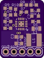
Does silkscreen work the same as solder mask, in that it sorta "repels" molten solder away from it? I really don't know, but I've been assuming that it doesn't. In fact, I've gone out of my way to move silkscreen away from the solder pads out of fear it might contribute to inadvertent solder bridging between pads.
Anyone know?
I see now why your board has 10 resistors instead of TI's reference schmatic's 9 resistors. It's because there doesn't seem to exist an off-the-shelf 15.62M-Ohm 0609 resistor, even though TI apparently thinks such a component does exist. I know Digikey doesn't stock any 15.62M-Ohm 0609 resistors, that's for sure. So, your two series resistors are probably a 15M-Ohm resistor and a 620K-Ohm resistor, both of which Digikey sells.
-
I see now why your board has 10 resistors instead of TI's reference schmatic's 9 resistors. It's because there doesn't seem to exist an off-the-shelf 15.62M-Ohm 0609 resistor, even though TI apparently thinks such a component does exist. I know Digikey doesn't stock any 15.62M-Ohm 0609 resistors, that's for sure. So, your two series resistors are probably a 15M-Ohm resistor and a 620K-Ohm resistor, both of which Digikey sells.
@scalz
I worked out the following as the mapping from resistor labels on your board to resistor values (assuming the target is Figure 14 from the DS):
R1 = 4.42M
R2 = 15M
R3 = 620K
R4 = 1.43M
R5 = 4.22M
R6 = 4.42M
R7 = 4.02M
R8 = 5.9M
R9 = 4.42M
R10 = 5.6M -
i don't remember, i'll look at this later. but i posted the schematic some posts above if it can help.
From the fab I've already received my board, your board, and obvioiusly the "stripped" board (photos above). On Thursday I should receive from Digikey resistors with precisely the values in the above list. I'll then be able to finish assembling the boards and see how their performance compares. TI has a paper for measuring the BQ25504 efficiency: http://www.ti.com/lit/an/slua691/slua691.pdf
-
From the fab I've already received my board, your board, and obvioiusly the "stripped" board (photos above). On Thursday I should receive from Digikey resistors with precisely the values in the above list. I'll then be able to finish assembling the boards and see how their performance compares. TI has a paper for measuring the BQ25504 efficiency: http://www.ti.com/lit/an/slua691/slua691.pdf
@scalz
I assembled both your board and my board today and did a quick test. The good news is that both boards appear to function with a cold start voltage of about 330mv, and for that reason it appears that both boards outperform the Tindie board. I am guessing that is, at least in part, because they use one of the datasheets recommended inductors, as compared to the Tindie Board, which does not appear to. -
I've played with the BQ25504 boards only a little bit thus far, but the truth that the datasheet glossed over in the executive summary section is that at the very low voltages (330mv+), the efficiency is terrible up until it charges up the caps to reach a threshhold voltage of around 2 volts or so. Those ultra-low voltages are the "cold start" phase, and the aim of that is, apparently, to bootstrap itself using available energy up to the threshhold voltage (maybe there's a better term for it). So, the trick to using this chip appears to be to maintain at least the threshhold voltage on the caps. You really don't want to ever invoke the cold start mechanism, because the the cold start efficiency appears to be quite miserable. So, while it is true to say that it works at ultra low voltages, it's just a partial truth that leaves a lot unsaid.
So, if one starts with the assumption that a relatively high voltage (say 2 volts, give or take) must be maintained on the caps in order for this to be practical, it really has me wondering now how this chip compares to other boost chips under the same assumptions. Fortunately, I have test boards for a number of different kinds of boost chips already in the pipeline. :smile:
-
I've played with the BQ25504 boards only a little bit thus far, but the truth that the datasheet glossed over in the executive summary section is that at the very low voltages (330mv+), the efficiency is terrible up until it charges up the caps to reach a threshhold voltage of around 2 volts or so. Those ultra-low voltages are the "cold start" phase, and the aim of that is, apparently, to bootstrap itself using available energy up to the threshhold voltage (maybe there's a better term for it). So, the trick to using this chip appears to be to maintain at least the threshhold voltage on the caps. You really don't want to ever invoke the cold start mechanism, because the the cold start efficiency appears to be quite miserable. So, while it is true to say that it works at ultra low voltages, it's just a partial truth that leaves a lot unsaid.
So, if one starts with the assumption that a relatively high voltage (say 2 volts, give or take) must be maintained on the caps in order for this to be practical, it really has me wondering now how this chip compares to other boost chips under the same assumptions. Fortunately, I have test boards for a number of different kinds of boost chips already in the pipeline. :smile:
A closer reading of the cold start section of the datasheet (Section 8.4) confirms my initial observations. VSTOR_CHGEN is what I was calling the "threshhold voltage" and is typically around 1.8v. VSTOR must be greater than VSTOR_CHGEN before cold start ends. The datasheet conceeds that cold start runs an "inefficient" boost converter. Just how inefficient? Well, I haven't seen any curves in the datasheet that answer that precisely (perhaps they were deleted by the marketing department?). Apparently, if you want to know that vital information, you have to compile your own data. I guess TI either doesn't know themselves (unlikely), or they're just not sharing.. Gee, thanks TI
However, the reality is worse than what I initially surmised, especially if using a supercap: That's because a discharged supercap will crash VSTOR, and so the chip could remain stranded in cold-start mode. Quoting the datasheet: "When large, discharged super capacitors with high DC leakage currents are attached, the intial charge time can be signficant." Yeah, no kidding. But, it appears there's also a notion for how to workaround this problem: "It is highly recommended to add an external PFET between the system load and VSTOR. An inverted VBAT_OK signal can be used to drive the gate of this system-isolating, external PFET."
So..... now I need to figure out the brass tacks of how to do that and probably redo the PCB to include such a PFET.
-
I think I'll try using a load switch. That way I can use the BAT_OK signal directly, without having to invert it. What I don't presently know is how fast the BAT_OK signal changes. If it lags considerably, then there's a risk that VSTOR might fall back into the cold start region before the current draining from vstor into the supercap can be shut off.
-
I found this curve:
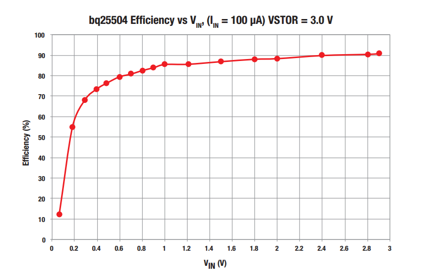
not in the datasheet, but here: http://www.ti.com/lit/ml/slpt026a/slpt026a.pdfYou'll note that it shows VSTOR = 3.0V, which I think is probably key to getting anything worthwhile from this chip. Anyhow, as long as VSTOR=3.0V, it's a pretty impressive curve.
-
TI makes an "ultra low leakage load switch" which might be a good fit: http://www.ti.com/lit/ds/symlink/tps22860.pdf
-
TI makes an "ultra low leakage load switch" which might be a good fit: http://www.ti.com/lit/ds/symlink/tps22860.pdf
OK, I just put together a breakout board for the TPS22860 to audition it for this new role. I just now sent it to the fab, so it will be another two weeks (!) before I'll know. I just hate how these fab iterations stretch these projects out far too long.
-
So, what should the programmed voltage cut-off's be? Here's my first pass at that:
VBAT_UV = 0 volts. // it's a capacitor, so you can't overdischarge it.
VBAT_OV = 3.6 volts // because we don't want to run the mote at more than 3.6 volts.
VBAT_UV_HYST = 1.9v. // Note sure. To avoid the cold start inefficiency if the supercap is flat, it shouldn't be lower than 1.8v. If the VSTOR cap is ultra low leakage, then maybe 1.9v would keep the BQ25504 out of the cold start zone for long enough (?). If not, I might need to utilize a higher capacitance VSTOR.
VBAT_OV_HYST = 2.0v. // Another guess. Needs to be higher than VBAT_UV_HYST, or there won't be any charge to transfer to the supercap. On the other hand, a higher voltage would lead to greater inefficiency if the supercap voltage is low.
As long as the supercap's voltage is above VBAT_UV_HYST, then the supercap and VSTOR will remain connected.
Translating the above programmed voltages into resistor values that can be purchased on Digikey yields the following:
ROV1 = 5.1M
ROV2 = 4.7M
ROK1 = 6.2M
ROK2 = 3.3M
ROK3 = 510K
RUV1 = 10M
RUV2 = 0 or 1 ohm (doesn't matter which) -
I received the MCP1640 boost converter board from the fab yesterday, and so I put it together. It works, but I can see now why it' (and probably most boost converter boards not intended for solar) is a bad fit for solar: basically the lower the input voltage, the higher the input current that's required in order to generate current at the output voltage. However, under low light circumstances, when a small solar panel will have low voltage, it is precisely the time when it also won't be able to supply much current either. So, without modification, it's a poor match for what's needed.
What would be needed to make it work is a mechanism to throttle the output voltage and output current to better match the limited input voltage and input current that's available. I suspect that mechanism is basically what MPPT is. So, if one were to replace the fixed resistors on the MCP1640 board with a potentiometer, one could manually do MPPT. But that obviously isn't practical, so one could instead use an mcu and a digital potentiometer, together with voltage and current sensors, to accomplish the same. That would probably work, but it leaves open the bootstrap problem: how could you power that equipment from a cold start scenario?
So, I think this does give insight as to why the BQ25504 behaves as it does. Rather than using an mcu and generic voltage and current sensors, it uses specialized hardware to accomplish the same result. However, just like an mcu, that hardware can't work from a cold start, and so the whole setup wallows in high inefficiency until it can emerge from the cold start.
-
On the other hand, since I'm sure to have an mcu in just about any mysensor-type project, why not leverage it? If there exist (?) low-voltage boost converters that are easily mcu controllable, that might be worth exploring.
@NeverDie you have probably already seen this, but in case you havent: mouser has a great article on mppt http://www.mouser.se/applications/solar-panel-power-tracking/
http://www.limpkin.fr/index.php?post/2011/12/07/Indoor-solar-energy-harvesting%3A-a-platform-to-(finally)-get-some-numbers has some hard data on how much power one person managed to get.
I haven't built anything like this yet, but I am following your progress because I would like some of my sensors to be self-powered in the future.
-
i read this one too. his next article is http://www.limpkin.fr/index.php?post/2012/03/20/Indoor-solar-energy-harvesting%3A-3-months-data
and i studied this one http://www.ti.com.cn/cn/lit/ug/tidub22b/tidub22b.pdf when i did my choice about overall cost, if i wanted reliable delivery and signing packet, for my multisensors..so i thought that would add too much overhead on my specific device (cost) but this chip is very nice for simple, low power BLE like, short burst ;) -
i read this one too. his next article is http://www.limpkin.fr/index.php?post/2012/03/20/Indoor-solar-energy-harvesting%3A-3-months-data
and i studied this one http://www.ti.com.cn/cn/lit/ug/tidub22b/tidub22b.pdf when i did my choice about overall cost, if i wanted reliable delivery and signing packet, for my multisensors..so i thought that would add too much overhead on my specific device (cost) but this chip is very nice for simple, low power BLE like, short burst ;)Thanks for the articles, guys.
The TI article takes the approach of running off a battery when there's not enough solar. Although that feels a bit like cheating, it might be valid if used just to power an MCU rather than do a full cold start before that's possible. Another approach would be to use something like an LTC3108, which is a boost converter optimized to boost very, very low voltage/current values. Maybe that could power an MCU much more quickly than rely only on the cold start abilities of the BQ25504. Perhaps it would turn out that an LTC3108 would be sufficient, all by itself. I think it's worth exploring.
-
Also, a larger, higher voltage panel coupled with a buck-boost converter (https://www.openhardware.io/view/276/33v-Buck-Boost-DC-DC-Converter) might offer another solution, perhaps one that isn't so affected by cold start issues.
Of course, some might simply use a larger, higher voltage panel directly wired to the supercap, without any intermediating converter. I'm not sure how that compares in performance, but it does have the virtue of simplicity.
-
Jeelabs has some nice posts on startup power:
http://jeelabs.org/2013/03/29/jeenode-micro-start-up-power/index.html
http://jeelabs.org/2012/12/29/rfm12b-startup-power-consumption/index.html
http://jeelabs.org/2012/09/09/delayed-power-up/index.html
http://jeelabs.org/2012/05/29/its-about-survival/index.html