💬 RFM69 Livolo 2 channels 1 way EU switch(VL-C700X-1 Ver: B8)
-
Indeed it is !
Livolo also sells some "lighting adapters" that do the same job than the parallel capacitor but a bit more advanced and I think a bit more efficient. These are probably not necessary all the time, I had no problem to power a pro-mini and a nrf24 from the livolo switch when I tried. But as I have a US/AU version made to have up to 4 relays the supply might be a little bit more tolerant.
https://www.aliexpress.com/store/product/Free-Shipping-Livolo-Lighting-Adapter-The-Saviour-Of-The-Low-wattage-LED-Lamp-White-Plastic-Materials/500715_1630968581.html?spm=2114.12010612.0.0.cTB2pcI started to solder my first PCBs for the US/AU switches, I suffered with my first SMD atmega but it's in place and running fine now :D I hope to finish a first board and test it on a real livolo switch next week.
The relay used on these boards is the latching type. So it doesn't require much power to operate as it needs only a small duration voltage pulse to energize the corresponding coil(set or reset) and the rest is done by the integrated mechanical part in combination with some magnet so that it stays "latched" in one position. This way we don't need to keep the relay coil energized all the time in order to keep the contacts ON so it's a let's say "low power" relay. The disadvantage is that it needs 2 digital pins to operate it if it's the 2 coils version and a H-bridge I presume if it's the single coil version(this one needs the polarity reversed on the coil in order to latch between the ON/OFF state). And another thing is that because of the above mentioned "latching" property this device has "memory" so we need to take care of that too as to not leave the lights ON for example in case of power failure. This can be easily achieved when the microcontroller starts in the "setup" routine by resetting the relays(I already tested this part and it works).
Now I know that these livolo switches have 2 more pins on the boards connector marked V_SENSE1 and V_SENSE2 if I remember well - I presume that those provide some voltage based on the relays state ON or OFF? I didn't tested that yet so I'm not sure if it's true(it would be great to be so as we can query the switch state using those signals instead of creating some variables in the sketch to hold the relays state).
-
Yes I have noticed they are latched as on the US/AU switches the MCU doesn't have enough pins and it needs a decoder to control up to 8 latches with 3 MCU pins. But still there are 4 leds to switch on, and maybe a bit more reserve power in case you switch all switches in a very short time ? Or maybe it's just that I use them with bulbs/tubes that allow more current to pass through :)
It contains a bunch of components, it's more than just a capacitor. You can have a look here :
http://mysku.ru/blog/aliexpress/30094.html -
Yes I have noticed they are latched as on the US/AU switches the MCU doesn't have enough pins and it needs a decoder to control up to 8 latches with 3 MCU pins. But still there are 4 leds to switch on, and maybe a bit more reserve power in case you switch all switches in a very short time ? Or maybe it's just that I use them with bulbs/tubes that allow more current to pass through :)
It contains a bunch of components, it's more than just a capacitor. You can have a look here :
http://mysku.ru/blog/aliexpress/30094.htmlIndeed it seems that it's not just a simple capacitor inside it. Well the whole purpose of it and also when using a capacitor in parallel with the light bulb is to have more current to pass through the series circuit so that the livolo power supply can provide much more power in the standby mode(when the light is OFF).
Take for example the simple capacitor: we know that when used in AC circuits it has a reactance which is kind of a resistance with a value that depends on the capacity and AC frequency. So if it's mounted in parallel with the load it reduces the overall resistance that the light bulb may impose in the circuit. We know that in a parallel circuit the lowest resistance element wins right? This way if we choose a proper value capacitor we can reduce the overall resistance in the circuit so more current can flow - this is needed in the OFF state as the standby circuit is weaker in this case. In the ON state the load is powered and much more current flows in the series circuit so no problems here. The only drawback in the ON state is to not use a too big capacitor so that it draws more current than necessary (it's in parallel with the load remember?) - in this case the light bulb could not work properly as it's bypassed by the capacitor so to speak. I used a 470nF capacitor with enough voltage rating and it works just fine...I will test with a 100nF capacitor too.
-
Yes I have noticed they are latched as on the US/AU switches the MCU doesn't have enough pins and it needs a decoder to control up to 8 latches with 3 MCU pins. But still there are 4 leds to switch on, and maybe a bit more reserve power in case you switch all switches in a very short time ? Or maybe it's just that I use them with bulbs/tubes that allow more current to pass through :)
It contains a bunch of components, it's more than just a capacitor. You can have a look here :
http://mysku.ru/blog/aliexpress/30094.htmlI think that device you sent earlier it's a power MOSFET based circuit. A MOSFET it's basically a voltage controlled resistance so it's a more "dynamic" way of controlling the bypassing "resistance" on the light bulb than using a simple capacitor which has a fixed reactance(AC equivalent resistance). I can see on the bottom side that it has some diodes which are needed because the MOSFET normally works in DC circuits so by using those we can assure that the current flows through it in one way as required. One example of such a circuit is here: http://forum.allaboutcircuits.com/blog/controlling-an-ac-load-with-a-mosfet.518
The above circuit is for controlling AC loads using MOSFET's so it's not related to our case but to ensure correct DC functionality I think they use the same ideas with diodes. The rest of components are for MOSFET gate proper driving I presume.
Another advantage of using that mosfet based circuit is that it's much smaller than using single capacitors. Capacitors tend to be bulky as the capacitance and/or voltage rating increases. Just my 2 cents here.
-
I think that device you sent earlier it's a power MOSFET based circuit. A MOSFET it's basically a voltage controlled resistance so it's a more "dynamic" way of controlling the bypassing "resistance" on the light bulb than using a simple capacitor which has a fixed reactance(AC equivalent resistance). I can see on the bottom side that it has some diodes which are needed because the MOSFET normally works in DC circuits so by using those we can assure that the current flows through it in one way as required. One example of such a circuit is here: http://forum.allaboutcircuits.com/blog/controlling-an-ac-load-with-a-mosfet.518
The above circuit is for controlling AC loads using MOSFET's so it's not related to our case but to ensure correct DC functionality I think they use the same ideas with diodes. The rest of components are for MOSFET gate proper driving I presume.
Another advantage of using that mosfet based circuit is that it's much smaller than using single capacitors. Capacitors tend to be bulky as the capacitance and/or voltage rating increases. Just my 2 cents here.
Hi @mtiutiu, You are the genius !!!.
I'm really happy to hear that you've finally achieved the desired results. Believe me that joy is mine if on anything but minimal I have contributed to you can achieve the desired goal.
I firmly believe that your development is the one that with difference and from my modest point of view has the key to success both because of its general approach and the fabulous development that I see you are performing in the accurate design of the additional circuit and I am sure that this design will be the future reference to give the Livolo's the possibility about true bidirectional RF control.Regarding the circuit that Livolo sells to avoid the problems of switch flickering by low power loads (less than 3W) this is a circuit with active components and is not a circuit designed to provide more power but to guarantee the switch of a " minimum " but regulated and constant current and providing it with better immunity because the current fluctuations caused by some electronic loads (led and similar) when they are at rest.
So it is not at all something that can be compared to the function of the capacitor in parallel to the load that provides an absolute increase of the current flow through the load circuit (and therefore of the switch) due to its behavior resistive in AC (more correctly its impedance), and this last is the characteristic that here we are looking for.
Just point out that a couple of details regarding the use of a capacitor in this way, and is that the consumption will be constant activated the load or not although we speak of an increase in very low consumption (100ma @ 220V = 2.5W aprox) but should not be neglected if we intend to "modify" by this way a relatively high number of loads and in this cases I think at least imposes a previous calculation of the constant power that we will increased because of add a "pile" of parallel load caps.
Also not should we lose on sight the fact that we will introduce a reactive component (reactive power) that can affect the character of our electrical installation and that as I say if it is used generically in many loads it is necessary to calculate its effect in our installation to avoid some displeasure with our electric company and their invoices.Finally let's do some simple math to calculate a capacitor value that might be appropriate.
Thus, the capacitive reactance is expressed as Xc = 1 / (w * C) where w is omega (equals 2 * pi * f, where f is the frequency) and C is the capacity in farads.
So if we wanted to have 20ma at 220V we would need a resistance of 4K (obviously I not do here this calculation of the simple ohm law) and therefore in my country that we have 50Hz frequency the capacity we would need would be C = 1 / (w * Xc) => C = 1 / (314 * 4000 ) = 729nFSumming up the capacitor you have tested on 470nf gives you a constant current of about 15ma when the circuit is in standby (load off), and don't forget we have a capacitor so we can achieve much more current from his reserve (this is for what was designed) and we can manage the current peak draw when RF transceiver are full active working on sending (Hope RFM69W/HW typically have current peaks over 30-40 ma on 100-200ms duration on sending cicles at full RF power) and seeing all seams should be enough to power any RF transceiver and a low power mcu if its consumption is well controlled by its proper use.
With this capacitor we are increasing the consumption of the load circuit in only about 0.5W, but let's not forget that this will be constant consumption in 24/365 hours / days a year.
So I keep close tuned with your evolution here.
Best regards
-
Hi @mtiutiu, You are the genius !!!.
I'm really happy to hear that you've finally achieved the desired results. Believe me that joy is mine if on anything but minimal I have contributed to you can achieve the desired goal.
I firmly believe that your development is the one that with difference and from my modest point of view has the key to success both because of its general approach and the fabulous development that I see you are performing in the accurate design of the additional circuit and I am sure that this design will be the future reference to give the Livolo's the possibility about true bidirectional RF control.Regarding the circuit that Livolo sells to avoid the problems of switch flickering by low power loads (less than 3W) this is a circuit with active components and is not a circuit designed to provide more power but to guarantee the switch of a " minimum " but regulated and constant current and providing it with better immunity because the current fluctuations caused by some electronic loads (led and similar) when they are at rest.
So it is not at all something that can be compared to the function of the capacitor in parallel to the load that provides an absolute increase of the current flow through the load circuit (and therefore of the switch) due to its behavior resistive in AC (more correctly its impedance), and this last is the characteristic that here we are looking for.
Just point out that a couple of details regarding the use of a capacitor in this way, and is that the consumption will be constant activated the load or not although we speak of an increase in very low consumption (100ma @ 220V = 2.5W aprox) but should not be neglected if we intend to "modify" by this way a relatively high number of loads and in this cases I think at least imposes a previous calculation of the constant power that we will increased because of add a "pile" of parallel load caps.
Also not should we lose on sight the fact that we will introduce a reactive component (reactive power) that can affect the character of our electrical installation and that as I say if it is used generically in many loads it is necessary to calculate its effect in our installation to avoid some displeasure with our electric company and their invoices.Finally let's do some simple math to calculate a capacitor value that might be appropriate.
Thus, the capacitive reactance is expressed as Xc = 1 / (w * C) where w is omega (equals 2 * pi * f, where f is the frequency) and C is the capacity in farads.
So if we wanted to have 20ma at 220V we would need a resistance of 4K (obviously I not do here this calculation of the simple ohm law) and therefore in my country that we have 50Hz frequency the capacity we would need would be C = 1 / (w * Xc) => C = 1 / (314 * 4000 ) = 729nFSumming up the capacitor you have tested on 470nf gives you a constant current of about 15ma when the circuit is in standby (load off), and don't forget we have a capacitor so we can achieve much more current from his reserve (this is for what was designed) and we can manage the current peak draw when RF transceiver are full active working on sending (Hope RFM69W/HW typically have current peaks over 30-40 ma on 100-200ms duration on sending cicles at full RF power) and seeing all seams should be enough to power any RF transceiver and a low power mcu if its consumption is well controlled by its proper use.
With this capacitor we are increasing the consumption of the load circuit in only about 0.5W, but let's not forget that this will be constant consumption in 24/365 hours / days a year.
So I keep close tuned with your evolution here.
Best regards
Yes you're right about the mosfet circuit - I think I've gone too far with it :simple_smile: . The rest of the circuit analysis was already done by computing the capacitor reactance in AC(I used the well known formula that you already mentioned). The second part regarding the reactive power/energy which these elements(capacitor and/or inductance) are creating - well, that part I didn't took into consideration yet and you're right here too. But for small capacitor values I don't think it will matter that much - well it matters when you have lots of them spread in the house for every light - that's true. In this case I assume that the power factor(and the power factor correction) needs to be taken into consideration as not all light bulbs today are simple light bulbs but in turn may contain power supply circuits too with reactive elements inside - like those which are using LEDs or fluorescent ones.
But for now I don't know of any other solution to work with these live wire only power supplies in order to provide enough current for this project. As I've seen you know much more than me regarding power electronics and AC circuits in general so on this part I still have things to learn(as with electronics in general).
Thanks once again for your help. I appreciate it.
-
Yes you're right about the mosfet circuit - I think I've gone too far with it :simple_smile: . The rest of the circuit analysis was already done by computing the capacitor reactance in AC(I used the well known formula that you already mentioned). The second part regarding the reactive power/energy which these elements(capacitor and/or inductance) are creating - well, that part I didn't took into consideration yet and you're right here too. But for small capacitor values I don't think it will matter that much - well it matters when you have lots of them spread in the house for every light - that's true. In this case I assume that the power factor(and the power factor correction) needs to be taken into consideration as not all light bulbs today are simple light bulbs but in turn may contain power supply circuits too with reactive elements inside - like those which are using LEDs or fluorescent ones.
But for now I don't know of any other solution to work with these live wire only power supplies in order to provide enough current for this project. As I've seen you know much more than me regarding power electronics and AC circuits in general so on this part I still have things to learn(as with electronics in general).
Thanks once again for your help. I appreciate it.
I totally agree about all your observations.
In our typically use case (on house with maybe 10-20 switch´s total) all my considerations about reactive power and consum increase can be totally overlooked because we are on really small values, but I think we need make all the important and proper warnings for anyone try to use on "any" environment.
And I think is so very difficult to find any other alternative solution to the proposed, which I insist that in any case and according to all the data we have is fully adjusted and satisfactory to our needs.
Thanks to you.
My best wishes
-
Tested the livolo mysensors node(RFM69W) with a 5W LED bulb and a 100nf/400Vca capacitor across it and it works perfectly(the modifications mentioned in this post: https://forum.mysensors.org/topic/2775/livolo-glass-panel-touch-light-wall-switch-Arduino-433mhz/63 were preserved).
The power required by the custom livolo front plate is about: (50-60)mA x 3.3V ~= 180-200mW at peak(when the radio is in TX mode) and the internal livolo power supply provides about 12-14V which in turn means the max current needed from it is about: 180-200mW / 12-14V = 15~16mA.
A 100nF capacitor has a reactance of ~31.83Kohms at a frequency of 50Hz which means the current it allows in the series circuit when the light is OFF(excluding the internal resistance/reactance of the livolo power switch) is about: 220-230Vac / 31.83Kohm ~= 7mA. To this value the light bulb current in the OFF state needs to be summed up as it's in parallel with the capacitor so maybe we get around 10-12mA in total which is more or less close to the above 15~16mA.
Now the above computations are very rough ones and based on effective values(as we have an AC circuit under analysis) and without taking into consideration the internal livolo power supply resistance and the one that the light bulb has in reality.
Okay. According to your observations 200mw (peak) is required to feed the additional RF plate and to that must be added the self-consumption of the Livolo's power circuit.
I believe that in this case, it is not so important to calculate the peak power because given the dynamic of our operation (the peak power transmissions usually need a few ms), I'm certain that this peak power can be easily provided by the own current reserve stored in the capacitor itself, and because that I think is necessary focus tries to guarantee the stable supply of current for the "normal" operation of both circuits (additional plate and livolo), and that requires at least 15ma (I think that is the min) and much better if we can guarantee about 20-30ma.
In the next link you can see a fairly exhaustive analysis of current variations vs RF output power in a typical RFM69HW operation, which shows that the average current is around 20-30ma and the peaks can reach 80ma:
So trying to make a global vision of the power needs for that project in general and taking into account that usually we will always ignore the true capacity to generate current of the several type of loads that can be connected, the different topology of housing wiring (self-capacity, spur, etc ...), the huge variations in impedance of the loads according to their type, their dynamics of operation, etc. I think is much more reasonable and closer to the real needs use capacitors of at least 470nf min (although I would opt for 680nf or maybe 1uf), to guarantee that there will always be a enough constant current supply capacity really closer or exceeds demanded in any circumstances.
Therefore I would not consider so much in calculations the capacity of the own loads for the power supply and only would calculate the capacity of supply by using the correct value of the capacitor that in any case will have to be installed.I think it is very important to guarantee the stability of the circuit operation (speaking in the long term) given the "infinite" possibilities of characteristics so variable that can be found in the installations of any house.
Collaterall efffect: When installing this capacitor we removed the load limitation of > 3w for Livolo's Switch, so generally now they can be used "independently" of the power and type of the load.
We have just solved a serious problem for Livolo manufacturers :smile:
Regards.
-
Okay. According to your observations 200mw (peak) is required to feed the additional RF plate and to that must be added the self-consumption of the Livolo's power circuit.
I believe that in this case, it is not so important to calculate the peak power because given the dynamic of our operation (the peak power transmissions usually need a few ms), I'm certain that this peak power can be easily provided by the own current reserve stored in the capacitor itself, and because that I think is necessary focus tries to guarantee the stable supply of current for the "normal" operation of both circuits (additional plate and livolo), and that requires at least 15ma (I think that is the min) and much better if we can guarantee about 20-30ma.
In the next link you can see a fairly exhaustive analysis of current variations vs RF output power in a typical RFM69HW operation, which shows that the average current is around 20-30ma and the peaks can reach 80ma:
So trying to make a global vision of the power needs for that project in general and taking into account that usually we will always ignore the true capacity to generate current of the several type of loads that can be connected, the different topology of housing wiring (self-capacity, spur, etc ...), the huge variations in impedance of the loads according to their type, their dynamics of operation, etc. I think is much more reasonable and closer to the real needs use capacitors of at least 470nf min (although I would opt for 680nf or maybe 1uf), to guarantee that there will always be a enough constant current supply capacity really closer or exceeds demanded in any circumstances.
Therefore I would not consider so much in calculations the capacity of the own loads for the power supply and only would calculate the capacity of supply by using the correct value of the capacitor that in any case will have to be installed.I think it is very important to guarantee the stability of the circuit operation (speaking in the long term) given the "infinite" possibilities of characteristics so variable that can be found in the installations of any house.
Collaterall efffect: When installing this capacitor we removed the load limitation of > 3w for Livolo's Switch, so generally now they can be used "independently" of the power and type of the load.
We have just solved a serious problem for Livolo manufacturers :smile:
Regards.
@jirm said in 💬 Livolo EU switch Mysensors integration:
We have just solved a serious problem for Livolo manufacturers :smile:
I don't think ther didn't know about that. I bought a cheap US/AU switch with no visible brand on the front plate. It has 3 switches and a radio receiver and I paid 12$ only. The power consumption seems much less optimized (I have one bulb flickering with this switch while it's fine with Livolo) so in the box, they provided a capacitor to put parallel to the load. I think they just prefer to sell the 3+$ "lighting adapter" :)
-
I suppose my question is a bit too early to ask, but what could the total price be for each complete switch? This is a truly awsome projekt, huge respect for your work!
-
I suppose my question is a bit too early to ask, but what could the total price be for each complete switch? This is a truly awsome projekt, huge respect for your work!
Hi,
Thanks. Well the prices vary depending from where you're sourcing the components. I will update the BOM using EU prices as I'm from EU. But if you can source them from aliexpress from example you can get them at half the price - maybe even a quarter(this depends also on the fact that you trust the China suppliers from there). I bought components from aliexpress and I think I had one unfortunate incident until now: some L6920 chips that I bought were defective and/or fake.
-
I received Livolo switches from aliexpress but main board connector is 2x7pin with 2mm pitch not 2x6 pitch 2.54mm...
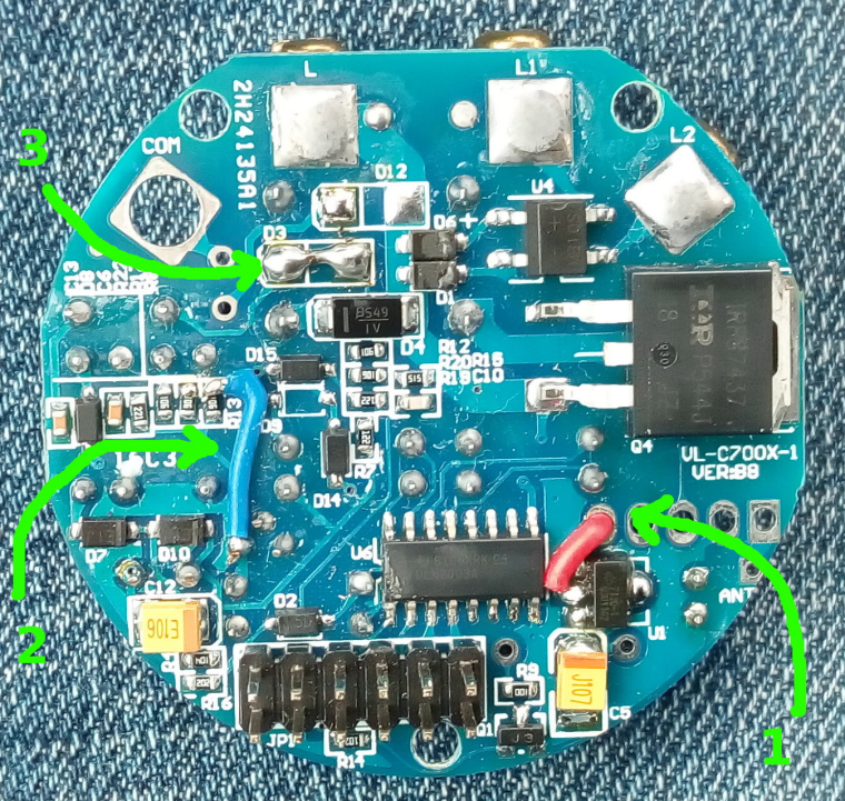
That's because you have another hw revision and maybe you bought a non-EU switch? I started this hw design using the EU variant because I'm from EU. I specified all these details in the project page too and for which hw revision of the board - quoting from there: "...the EU variant that I have(VL-C700X-1 Ver: B8)...". This hw revision of the board uses a 2x6 pin connector with 2.54mm pitch.
But if you can give me a dxf file with the front plate outline, touch sensors copper pads and 2x7 connector locations I can transpose that over the current board and do the arrangements so that it will align with yours too. One other thing that's needed is the 12V and 3V assignments to the 2x7 pin board connector and the relays drive pins too. I see here https://forum.mysensors.org/topic/2775/livolo-glass-panel-touch-light-wall-switch-arduino-433mhz/72# that @Nca78 posted that configuration but maybe you need to double check??
-
Yes I suggest a double check as mine is a US/AU format.
-
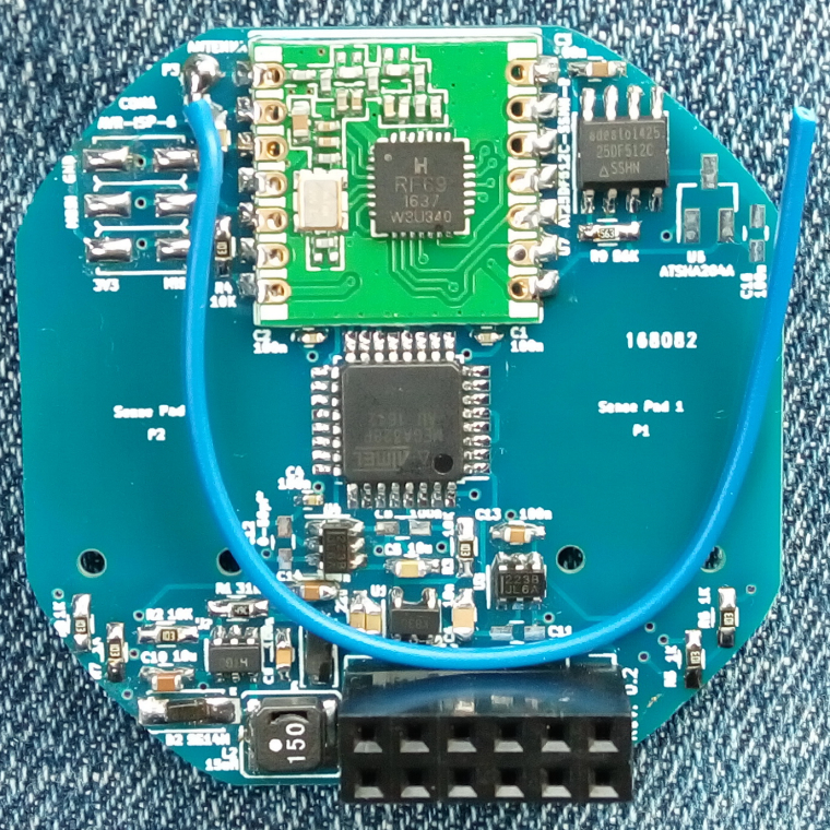
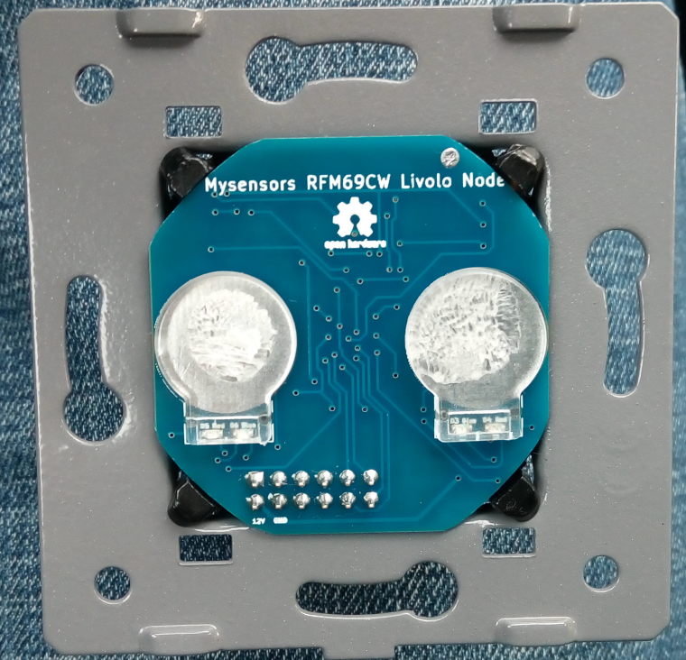
After a really long time I received the boards. I finished the assembly for one and uploaded some code to it. So far it seems to work but I need to perform some more tests. I attached some pictures of the finished product.
 .
.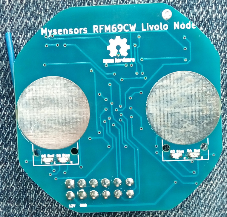
The silkscreen text is a little bit blurry and it was a little bit too small for the fab to print it so in some places is not right...anyways this is not important but the functionality is.
One note: the board round edges may be a little bit off the limits but that can be corrected by using some abrasive paper to remove the excess material(which I did in the above pictures and then the board fitted perfectly). -
After a really long time I received the boards. I finished the assembly for one and uploaded some code to it. So far it seems to work but I need to perform some more tests. I attached some pictures of the finished product.
. The silkscreen text is a little bit blurry and it was a little bit too small for the fab to print it so in some places is not right...anyways this is not important but the functionality is.
One note: the board round edges may be a little bit off the limits but that can be corrected by using some abrasive paper to remove the excess material(which I did in the above pictures and then the board fitted perfectly). -
I updated the project page on openhardware.io. Added instructions too. I hope that I didn't forget anything.
These are the modifications required for the power/relays board in order to work with this project:
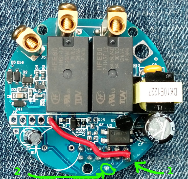
A capacitor is also needed in parallel with the light bulb otherwise the project board won't work as it doesn't get enough power from the standby circuit. I used a 470nF X2 type rated at 310Vac. I recommend using a light bulb of 10W or more(in my tests I used a 15W one.) I tested the setup with a 5W LED bulb but I got some instability from the livolo power supply board(it started to oscillate) - in this case maybe a bigger capacitor across the bulb might help(1uF one maybe). You don't need 2 capacitors in case of the 2 ways switch for each light bulb - one is sufficient across one of the bulbs.
Oh and please don't touch directly with your finger the sensor plates - use the plastics from the original board. I'm not responsible if you get an electric shock.
You can find more details in the project page on openhardware.io
Big thanks again to @jirm, @DJONvl and @Tigroenot and the rest of the community of course which contributed with the knowledge to make all this possible.
Hello! It looks like you're interested in this conversation, but you don't have an account yet.
Getting fed up of having to scroll through the same posts each visit? When you register for an account, you'll always come back to exactly where you were before, and choose to be notified of new replies (either via email, or push notification). You'll also be able to save bookmarks and upvote posts to show your appreciation to other community members.
With your input, this post could be even better 💗
Register Login