💬 RFM69 Livolo 2 channels 1 way EU switch(VL-C700X-1 Ver: B8)
-
Tested the livolo mysensors node(RFM69W) with a 5W LED bulb and a 100nf/400Vca capacitor across it and it works perfectly(the modifications mentioned in this post: https://forum.mysensors.org/topic/2775/livolo-glass-panel-touch-light-wall-switch-Arduino-433mhz/63 were preserved).
The power required by the custom livolo front plate is about: (50-60)mA x 3.3V ~= 180-200mW at peak(when the radio is in TX mode) and the internal livolo power supply provides about 12-14V which in turn means the max current needed from it is about: 180-200mW / 12-14V = 15~16mA.
A 100nF capacitor has a reactance of ~31.83Kohms at a frequency of 50Hz which means the current it allows in the series circuit when the light is OFF(excluding the internal resistance/reactance of the livolo power switch) is about: 220-230Vac / 31.83Kohm ~= 7mA. To this value the light bulb current in the OFF state needs to be summed up as it's in parallel with the capacitor so maybe we get around 10-12mA in total which is more or less close to the above 15~16mA.
Now the above computations are very rough ones and based on effective values(as we have an AC circuit under analysis) and without taking into consideration the internal livolo power supply resistance and the one that the light bulb has in reality.
Okay. According to your observations 200mw (peak) is required to feed the additional RF plate and to that must be added the self-consumption of the Livolo's power circuit.
I believe that in this case, it is not so important to calculate the peak power because given the dynamic of our operation (the peak power transmissions usually need a few ms), I'm certain that this peak power can be easily provided by the own current reserve stored in the capacitor itself, and because that I think is necessary focus tries to guarantee the stable supply of current for the "normal" operation of both circuits (additional plate and livolo), and that requires at least 15ma (I think that is the min) and much better if we can guarantee about 20-30ma.
In the next link you can see a fairly exhaustive analysis of current variations vs RF output power in a typical RFM69HW operation, which shows that the average current is around 20-30ma and the peaks can reach 80ma:
So trying to make a global vision of the power needs for that project in general and taking into account that usually we will always ignore the true capacity to generate current of the several type of loads that can be connected, the different topology of housing wiring (self-capacity, spur, etc ...), the huge variations in impedance of the loads according to their type, their dynamics of operation, etc. I think is much more reasonable and closer to the real needs use capacitors of at least 470nf min (although I would opt for 680nf or maybe 1uf), to guarantee that there will always be a enough constant current supply capacity really closer or exceeds demanded in any circumstances.
Therefore I would not consider so much in calculations the capacity of the own loads for the power supply and only would calculate the capacity of supply by using the correct value of the capacitor that in any case will have to be installed.I think it is very important to guarantee the stability of the circuit operation (speaking in the long term) given the "infinite" possibilities of characteristics so variable that can be found in the installations of any house.
Collaterall efffect: When installing this capacitor we removed the load limitation of > 3w for Livolo's Switch, so generally now they can be used "independently" of the power and type of the load.
We have just solved a serious problem for Livolo manufacturers :smile:
Regards.
-
Okay. According to your observations 200mw (peak) is required to feed the additional RF plate and to that must be added the self-consumption of the Livolo's power circuit.
I believe that in this case, it is not so important to calculate the peak power because given the dynamic of our operation (the peak power transmissions usually need a few ms), I'm certain that this peak power can be easily provided by the own current reserve stored in the capacitor itself, and because that I think is necessary focus tries to guarantee the stable supply of current for the "normal" operation of both circuits (additional plate and livolo), and that requires at least 15ma (I think that is the min) and much better if we can guarantee about 20-30ma.
In the next link you can see a fairly exhaustive analysis of current variations vs RF output power in a typical RFM69HW operation, which shows that the average current is around 20-30ma and the peaks can reach 80ma:
So trying to make a global vision of the power needs for that project in general and taking into account that usually we will always ignore the true capacity to generate current of the several type of loads that can be connected, the different topology of housing wiring (self-capacity, spur, etc ...), the huge variations in impedance of the loads according to their type, their dynamics of operation, etc. I think is much more reasonable and closer to the real needs use capacitors of at least 470nf min (although I would opt for 680nf or maybe 1uf), to guarantee that there will always be a enough constant current supply capacity really closer or exceeds demanded in any circumstances.
Therefore I would not consider so much in calculations the capacity of the own loads for the power supply and only would calculate the capacity of supply by using the correct value of the capacitor that in any case will have to be installed.I think it is very important to guarantee the stability of the circuit operation (speaking in the long term) given the "infinite" possibilities of characteristics so variable that can be found in the installations of any house.
Collaterall efffect: When installing this capacitor we removed the load limitation of > 3w for Livolo's Switch, so generally now they can be used "independently" of the power and type of the load.
We have just solved a serious problem for Livolo manufacturers :smile:
Regards.
@jirm said in 💬 Livolo EU switch Mysensors integration:
We have just solved a serious problem for Livolo manufacturers :smile:
I don't think ther didn't know about that. I bought a cheap US/AU switch with no visible brand on the front plate. It has 3 switches and a radio receiver and I paid 12$ only. The power consumption seems much less optimized (I have one bulb flickering with this switch while it's fine with Livolo) so in the box, they provided a capacitor to put parallel to the load. I think they just prefer to sell the 3+$ "lighting adapter" :)
-
I suppose my question is a bit too early to ask, but what could the total price be for each complete switch? This is a truly awsome projekt, huge respect for your work!
-
I suppose my question is a bit too early to ask, but what could the total price be for each complete switch? This is a truly awsome projekt, huge respect for your work!
Hi,
Thanks. Well the prices vary depending from where you're sourcing the components. I will update the BOM using EU prices as I'm from EU. But if you can source them from aliexpress from example you can get them at half the price - maybe even a quarter(this depends also on the fact that you trust the China suppliers from there). I bought components from aliexpress and I think I had one unfortunate incident until now: some L6920 chips that I bought were defective and/or fake.
-
I received Livolo switches from aliexpress but main board connector is 2x7pin with 2mm pitch not 2x6 pitch 2.54mm...
That's because you have another hw revision and maybe you bought a non-EU switch? I started this hw design using the EU variant because I'm from EU. I specified all these details in the project page too and for which hw revision of the board - quoting from there: "...the EU variant that I have(VL-C700X-1 Ver: B8)...". This hw revision of the board uses a 2x6 pin connector with 2.54mm pitch.
But if you can give me a dxf file with the front plate outline, touch sensors copper pads and 2x7 connector locations I can transpose that over the current board and do the arrangements so that it will align with yours too. One other thing that's needed is the 12V and 3V assignments to the 2x7 pin board connector and the relays drive pins too. I see here https://forum.mysensors.org/topic/2775/livolo-glass-panel-touch-light-wall-switch-arduino-433mhz/72# that @Nca78 posted that configuration but maybe you need to double check??
-
Yes I suggest a double check as mine is a US/AU format.
-
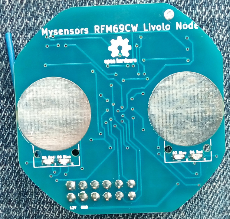
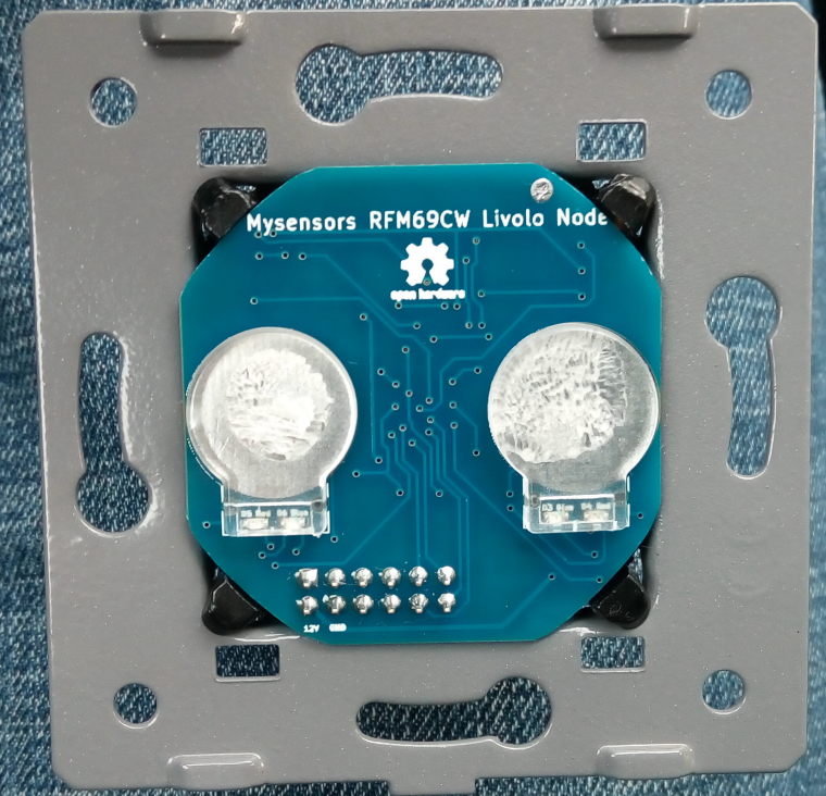
After a really long time I received the boards. I finished the assembly for one and uploaded some code to it. So far it seems to work but I need to perform some more tests. I attached some pictures of the finished product.
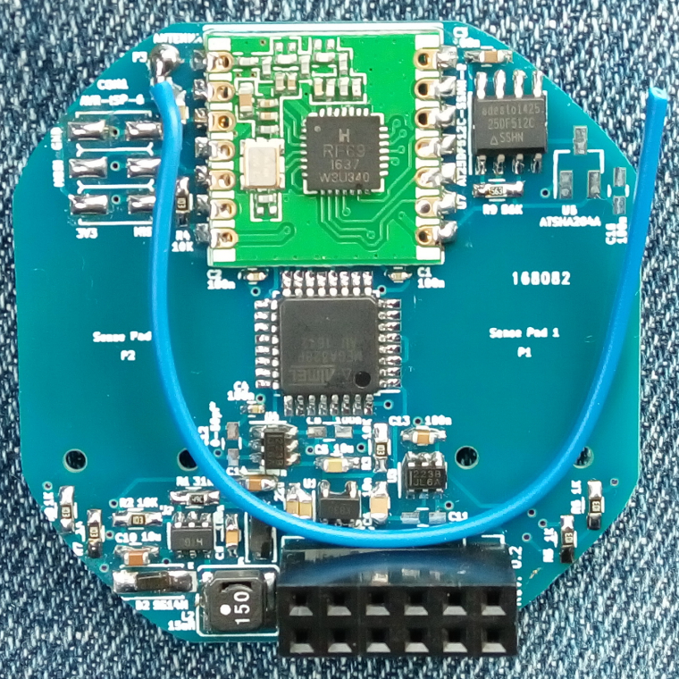 .
.
The silkscreen text is a little bit blurry and it was a little bit too small for the fab to print it so in some places is not right...anyways this is not important but the functionality is.
One note: the board round edges may be a little bit off the limits but that can be corrected by using some abrasive paper to remove the excess material(which I did in the above pictures and then the board fitted perfectly). -
After a really long time I received the boards. I finished the assembly for one and uploaded some code to it. So far it seems to work but I need to perform some more tests. I attached some pictures of the finished product.
. The silkscreen text is a little bit blurry and it was a little bit too small for the fab to print it so in some places is not right...anyways this is not important but the functionality is.
One note: the board round edges may be a little bit off the limits but that can be corrected by using some abrasive paper to remove the excess material(which I did in the above pictures and then the board fitted perfectly). -
I updated the project page on openhardware.io. Added instructions too. I hope that I didn't forget anything.
These are the modifications required for the power/relays board in order to work with this project:
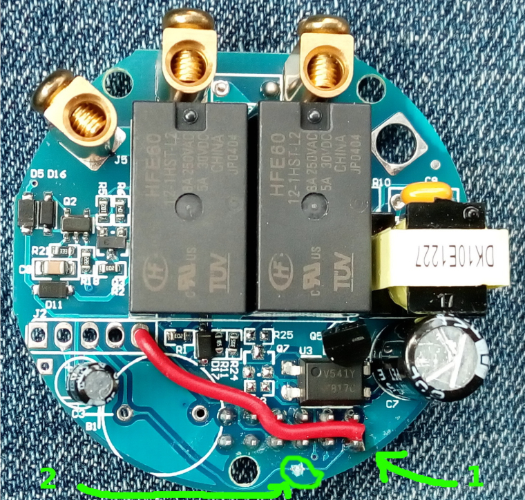
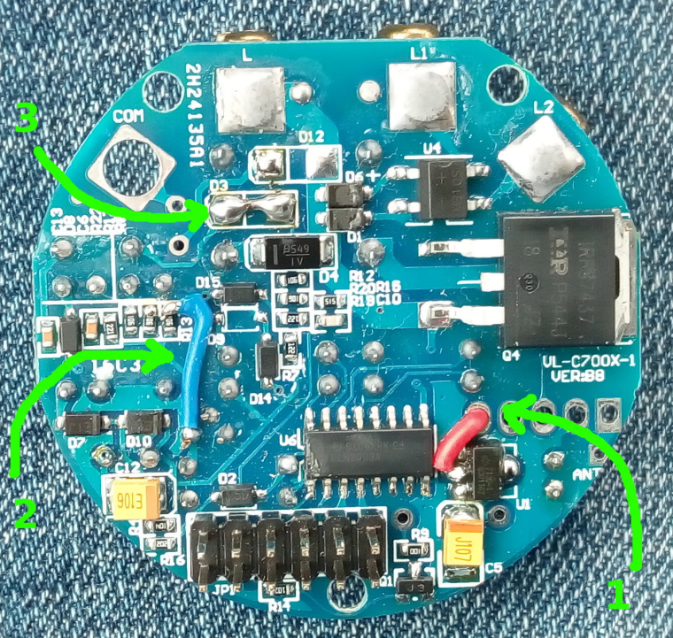
A capacitor is also needed in parallel with the light bulb otherwise the project board won't work as it doesn't get enough power from the standby circuit. I used a 470nF X2 type rated at 310Vac. I recommend using a light bulb of 10W or more(in my tests I used a 15W one.) I tested the setup with a 5W LED bulb but I got some instability from the livolo power supply board(it started to oscillate) - in this case maybe a bigger capacitor across the bulb might help(1uF one maybe). You don't need 2 capacitors in case of the 2 ways switch for each light bulb - one is sufficient across one of the bulbs.
Oh and please don't touch directly with your finger the sensor plates - use the plastics from the original board. I'm not responsible if you get an electric shock.
You can find more details in the project page on openhardware.io
Big thanks again to @jirm, @DJONvl and @Tigroenot and the rest of the community of course which contributed with the knowledge to make all this possible.
-
Hello,
i don't find anymore the VL-C700X-1 on aliexpress.
Can you tel me which is equal ?
Is it https://fr.aliexpress.com/store/product/Free-Shipping-Livolo-Luxury-White-Crystal-Glass-Switch-Panel-EU-Standard-VL-C701-11-110-250V/500715_512886492.html?spm=2114.12010612.0.0.deb0F4 ?Thx
-
Hello,
i don't find anymore the VL-C700X-1 on aliexpress.
Can you tel me which is equal ?
Is it https://fr.aliexpress.com/store/product/Free-Shipping-Livolo-Luxury-White-Crystal-Glass-Switch-Panel-EU-Standard-VL-C701-11-110-250V/500715_512886492.html?spm=2114.12010612.0.0.deb0F4 ?Thx
This one is: https://m.aliexpress.com/item/512770913.html
Please note that the board that I made is for the 2 channels model(VL-C702 series). Now I hope that they didn't changed the inside pcb hw revision meanwhile. The serial number that you mentioned and which I wrote about on openhardware project page is actually their pcb revision from inside the switch. I don't know for sure if that reflects the switch model which they advertise on AliExpress. But the link that I gave you is for the same switch which I bought some time ago because I took it from my orders list from my AliExpress account.
I see now that the price is bigger... it was 13$ when I bought it.
-
This one is: https://m.aliexpress.com/item/512770913.html
Please note that the board that I made is for the 2 channels model(VL-C702 series). Now I hope that they didn't changed the inside pcb hw revision meanwhile. The serial number that you mentioned and which I wrote about on openhardware project page is actually their pcb revision from inside the switch. I don't know for sure if that reflects the switch model which they advertise on AliExpress. But the link that I gave you is for the same switch which I bought some time ago because I took it from my orders list from my AliExpress account.
I see now that the price is bigger... it was 13$ when I bought it.
@mtiutiu Thanks you for your anwser ;)
Did you test a two way switch (va et viens) ?
I think we can do this with 1 gang 2 way :
https://fr.aliexpress.com/item/Black-Crystal-Glass-Switch-Livolo-EU-Standard-VL-C701SR-12-1-Gang-2-Way-Remote-Control/32786281129.html -
@mtiutiu Thanks you for your anwser ;)
Did you test a two way switch (va et viens) ?
I think we can do this with 1 gang 2 way :
https://fr.aliexpress.com/item/Black-Crystal-Glass-Switch-Livolo-EU-Standard-VL-C701SR-12-1-Gang-2-Way-Remote-Control/32786281129.htmlNo, I didn't tested a 2 way switch so I don't know how it behaves in that case. I don't have and I don't use switches with that setup.
-
This one is: https://m.aliexpress.com/item/512770913.html
Please note that the board that I made is for the 2 channels model(VL-C702 series). Now I hope that they didn't changed the inside pcb hw revision meanwhile. The serial number that you mentioned and which I wrote about on openhardware project page is actually their pcb revision from inside the switch. I don't know for sure if that reflects the switch model which they advertise on AliExpress. But the link that I gave you is for the same switch which I bought some time ago because I took it from my orders list from my AliExpress account.
I see now that the price is bigger... it was 13$ when I bought it.
Hi all
Can I suggest some improvements for that project?
For sure I agree with @tonnerre33 about make a version board for only one gang switch.
I buy regularly (once a month or so) some parts from livolo and from last 4 or 6 months I see that the switch plate boards (for the EU version) are the same on hardware specs at least from 6 or 9 month ago.
But we can expect that in near future (maybe few months) Livolo manufacturer make some changes and updates on his designs, because they regulary are doing that in past. So we need keep prepared for that and for make the propper updates to this project to mantain it working with the next version Livolo switchs.- -One gang switch I think is most common switch people have installed or at least I think is needed too with this two gang project version.
2.- Maybe will be better use (or make another plate board version) for the RFM69HW (high power), because the pinount on HW not match with RFM69CW you use, and HW type have same working specs but with the plus that HW type have high power possibilities and is most easy to find and both have similar price.
3.- How can be little better documented all the changes (wiring) we need do on the power relay plate board?
At least for me is hard to do correct wiring only seeing the photo and is easy to do some mistake trying to solder the wiring in the correct pins and places.
So I suggest trying to do some more work on that and maybe include some scheme and plan and take all best pic from each wiring bridge is needed to do that we can see without doubts the correct place to solder it.PD: @tonnerre33 I think one or two way switch function not be affected with this project plate board, because that function only differ on the pic (MCU) Livolo switch firmware and litles changes on power relay plate board to wire the additional pic pin output two way function to the COM connector.
Nothing of that function should be affected by anything that this plate modifies on the Livolo switch.My best wishes !
-
Hi all
Can I suggest some improvements for that project?
For sure I agree with @tonnerre33 about make a version board for only one gang switch.
I buy regularly (once a month or so) some parts from livolo and from last 4 or 6 months I see that the switch plate boards (for the EU version) are the same on hardware specs at least from 6 or 9 month ago.
But we can expect that in near future (maybe few months) Livolo manufacturer make some changes and updates on his designs, because they regulary are doing that in past. So we need keep prepared for that and for make the propper updates to this project to mantain it working with the next version Livolo switchs.- -One gang switch I think is most common switch people have installed or at least I think is needed too with this two gang project version.
2.- Maybe will be better use (or make another plate board version) for the RFM69HW (high power), because the pinount on HW not match with RFM69CW you use, and HW type have same working specs but with the plus that HW type have high power possibilities and is most easy to find and both have similar price.
3.- How can be little better documented all the changes (wiring) we need do on the power relay plate board?
At least for me is hard to do correct wiring only seeing the photo and is easy to do some mistake trying to solder the wiring in the correct pins and places.
So I suggest trying to do some more work on that and maybe include some scheme and plan and take all best pic from each wiring bridge is needed to do that we can see without doubts the correct place to solder it.PD: @tonnerre33 I think one or two way switch function not be affected with this project plate board, because that function only differ on the pic (MCU) Livolo switch firmware and litles changes on power relay plate board to wire the additional pic pin output two way function to the COM connector.
Nothing of that function should be affected by anything that this plate modifies on the Livolo switch.My best wishes !
@jirm said in 💬 Livolo EU switch Mysensors integration:
Nothing of that function should be affected by anything that this plate modifies on the Livolo switch.
I hope because i have many 2 way and the same for my futur home ;)
And what about NRF24L version ?
Many people are using RFM69 but 2.70$ RFM vs 1$ NRF ... Ok for command the sensitives nodes like roller shutters but why for the light ? -
No, I didn't tested a 2 way switch so I don't know how it behaves in that case. I don't have and I don't use switches with that setup.
@mtiutiu
Of course all we are here to help you make all the proper test needed with all Livolo parts that we speak. One or two gang with/and one or two way, other plate hardware revisions, etc...That all we need for do that is the avaibilitty to get your plate boards designs working on our houses.
Personally I'm so busy (and so lazy) to make all this project working from scratch trying to find plate board manufacturer, solder all (wooow smd) parts, etc... etc... and need if possible some at least "semi-mounted" plate boards printed and with the smd parts soldered.
-
@jirm said in 💬 Livolo EU switch Mysensors integration:
Nothing of that function should be affected by anything that this plate modifies on the Livolo switch.
I hope because i have many 2 way and the same for my futur home ;)
And what about NRF24L version ?
Many people are using RFM69 but 2.70$ RFM vs 1$ NRF ... Ok for command the sensitives nodes like roller shutters but why for the light ?Personally I think that much better specs from RFM vs NRF and the working radio band (433, 868 Mhz vs 2,4 Ghz) are most than enough reasons to spend that 2 $ more on RFM.
But...more always is better. So we can dream with another plate board version for NRF in the future...who knows
Hello! It looks like you're interested in this conversation, but you don't have an account yet.
Getting fed up of having to scroll through the same posts each visit? When you register for an account, you'll always come back to exactly where you were before, and choose to be notified of new replies (either via email, or push notification). You'll also be able to save bookmarks and upvote posts to show your appreciation to other community members.
With your input, this post could be even better 💗
Register Login