💬 RFM69 Livolo 2 channels 1 way EU switch(VL-C700X-1 Ver: B8)
-
Creating a new board with new hardware/new stuff like the ESP-01 is a thing that requires time and testing which is a luxury that I really don't have now. So I'm sorry but I won't invest time/money in creating/testing boards with ESP modules. The only thing that I'm going to do is to re-design the RFM board only as it doesn't require too much changes/work/time/money and it was tested beforehand.
-
Until I get my hands on the new switches I cannot say. The thing is that they use now a 2x7 connector instead of a 2x6 one. I don't know how the relays are mapped to the new one and the 3V line. But I think that for sure a new pcb needs to be created. But until then maybe @tonnerre33 can shed some light here with some pictures? Is the new connector mapped ok in your schematics?
If I see well in the pictures they moved the connector in the opposite direction so yeah...a new pcb design is needed.
And to be honest I cannot keep up with the Lenovo manufacturer and create every time a new pcb because they maybe didn't slept very well over night and decided to change hw revision of the power/relays board on which this project relies. This is overkill and it's a downside for this project as I need to rely on their power supply board.
Now as I promised I will create a new pcb for the new hw revision but ONLY for that and not the future ones. The new hw revision that they use now is the one that @tonnerre33 and @shabba has which is: VL-C702X-2 VER:C1
But @shabba there's @tonnerre33 who works on this and started ahead of me so maybe you two can sync up on this?
@mtiutiu Yes the new connector is mapped for the new version. I have checked the pins with the multimeter.
I have done many picture that you can see here :
http://www.photorapide.com/albums/jordan/kqadrk/livolo-vl-c702x-2-ver-c1.html
I hope you will find the informations that you want.
Caution if you look my schema for see the mapping of the pin because on my board the bottom is your top and the top your bottom ;)
Edit : I have added the mapping in the picture album
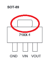
Did you know why the pin in red surrounded is connected to the VIN ?
-
@mtiutiu I'm not asking you to design the board again. If you can tell how to connect the ESP module to your board?
thanks for the advice
-
@mtiutiu Yes the new connector is mapped for the new version. I have checked the pins with the multimeter.
I have done many picture that you can see here :
http://www.photorapide.com/albums/jordan/kqadrk/livolo-vl-c702x-2-ver-c1.html
I hope you will find the informations that you want.
Caution if you look my schema for see the mapping of the pin because on my board the bottom is your top and the top your bottom ;)
Edit : I have added the mapping in the picture album
Did you know why the pin in red surrounded is connected to the VIN ?
Thanks for the pics and for your time. Well that's how the SOT-89 package is designed. If I'm not mistaking the big metallic pad was made like that for better thermal dissipation if you make the copper area which it connects to big enough. Now why it was specifically connected to Vin...that I'm afraid I don't know.
-
Ok...my bad. I didn't understand your initial question. But now the next question is: what do you want to accomplish exactly? Can you be more specific?
-
Just want to confirm that I also received a "VL-C702X-2 VER:C1" today in the mail so at least they haven't made yet another version.
-
Hello @mtiutiu i think i have finished my first version.
I have modified the pcb with your suggestions (power the node with 12VCC).
I have corrected a big mistake too, the AT25DF512C footprint was wrong (convertor mistake i think) ...I have to put 2 resistors on the prohibided face ^^ but normaly it should be ok
-
So besides the header being bigger what else has changed? I have received the current PCBs and wondering what I might need to do to make them still work?
@shabba said in 💬 Livolo 2 channels 1 way EU switch(VL-C700X-1 Ver: B8):
The position of the header has changed too. Now it's on the right part.
I think you can use your pcb but you'll need some wires between the femal header and the new mal header. -
@shabba said in 💬 Livolo 2 channels 1 way EU switch(VL-C700X-1 Ver: B8):
The position of the header has changed too. Now it's on the right part.
I think you can use your pcb but you'll need some wires between the femal header and the new mal header.@tonnerre33 Thanks - do you happen to know the pin out?
-
Yes, you can find the new pint out here :
http://www.photorapide.com/images.php?photoName=dm0l6i.jpg&photoId=1002306
-
Yes, you can find the new pint out here :
http://www.photorapide.com/images.php?photoName=dm0l6i.jpg&photoId=1002306
-
Hello @mtiutiu i think i have finished my first version.
I have modified the pcb with your suggestions (power the node with 12VCC).
I have corrected a big mistake too, the AT25DF512C footprint was wrong (convertor mistake i think) ...I have to put 2 resistors on the prohibided face ^^ but normaly it should be ok
@tonnerre33 I just browsed your Github repo, found nothing there today, you deleted the contents?
-
@tonnerre33 Thanks! Do you know the old one?
@shabba You can see the old one on the picture of this project ;)
@hhalibo Yes i'll push this project in the master branch only when i'll have test it. @mtiutiu is working on it too, i did this node for training me because i'll develop other livolo EU ;)
I think the mtiutiu node will be more optimised. I learned and i hope continu to learn many things with him. -
hi @mtiutiu - I see https://github.com/mtiutiu/kicad/tree/master/mysensors/node/livolo_EU_switch/VL-C702X-2_Ver_C1 - Is this good to be ordered? If you give me a link on where you get a % I would like to order from there.
Thanks.
It's not finished yet. That's just a draft for the upcoming new hardware. When it's finished I'll publish it. As I said all of my work is done using my free time. For now I'm on vacation...will start working again on this project next week.
-
How about this project now?
-
How about this project now?
It is abandoned, have a look at the description.
Hello! It looks like you're interested in this conversation, but you don't have an account yet.
Getting fed up of having to scroll through the same posts each visit? When you register for an account, you'll always come back to exactly where you were before, and choose to be notified of new replies (either via email, or push notification). You'll also be able to save bookmarks and upvote posts to show your appreciation to other community members.
With your input, this post could be even better 💗
Register Login