Current Sensing?


  • Admin

    Openenergymonity seem to resell "BBSP-LPD" by enistic.
    http://www.enistic.com/homepage?start=10


  • Hardware Contributor

    oki, keep the good work 😉
    i know in France people prefer DIN rails mounting. makes sense, but can be done in lot of ways..


  • Hardware Contributor

    Slightly off subject, and lets drop back onto subject after this question:

    Would you guys welcome a gateway enclosure that is modelled to fit onto a DIN RAIL? I might come up with some models for the different arduino setups for the gateways that people are running and create a few 3d printable models to put onto the build page too....


  • Hardware Contributor

    maybe useful for some people. but i wouldn't put my gw at this place imho..


  • Hardware Contributor

    @hek said in Current Sensing?:

    BBSP-LPD

    Do you have a link for the product on Openevergymonity? Can't find the product you're speaking of.


  • Admin

    A clamp sensing node would be a excellent fit in a DIN rail mount enclosure.


  • Admin


  • Hardware Contributor

    @hek - Do you think there would be a specific need for a clamp sensor over a LED sensor node? Do you possibly think that people would be clamping individual lines out of their fuse box rather than just wanting to know what the overall usage is?


  • Hardware Contributor

    maybe ot, but for the fun, someone selling iot devices for the electric cupboard, told me once, he had to have an expensive decennial insurance for selling his devices even if it's only connected to the serial protocol and his device is dc.. crazy! hopefully we know what we do 🙂


  • Hardware Contributor

    @hek Oh, that product we were talking about... Where about do you see that it is made by einstic? Other than the photo on einstic's site being the exact same sensor build?


  • Hardware Contributor

    @hek if i search in my folder archives, i'm pretty sure to find this 😀 (because i designed this a while, but never tried this one..). i mean the clamp sensor.
    Edit: ah oki the optical one..not done this one, not hard, i let it for you @Samuel235 😉 ive enough projects in progress, and i don't need it though lol


  • Admin

    @Samuel235, I was just looking at the picture 🙂

    An overall pulse sensor is really accurate and useful for whole house consumption.

    But clamps also has its applications.


  • Hardware Contributor

    I'm thinking that we could have the Pulse sensor for overall usage and then put clamps onto individual lines that we would want to monitor, such as upstairs lights, downstairs sockets, sheds, cookers. This is my idea rather than compicated nodes such as relay nodes to monitor the current usage. I feel that people don't really want to know how much their bedroom lights are using, they want to know how much energy is being used on all their lights. and then for example if they think its high, they replace all with LED lights. Just an example 🙂

    Do you guys feel the same way or do you like the idea of individual monitoring if it was already built into the node without you having to mess around making the nodes with them on there?

    I made my relay module with one on there because as a hardware designer it was interesting to have such, but after doing it and thinking about it, i think it may have been just the theory of implication that was a nice thought and that we wouldn't really care for it in reality....


  • Mod

    The boxed pulse sensor with velcro is the perfect solution, but it is darn expensive.
    Clamps are a solution, but in order to have power consumption you need also voltage reading and PFC calculation like THIS little project. Imho it is safer to use the pulse sensor 🙂


  • Hardware Contributor

    @gohan I think we're all thinking that pulse is the better option for overall monitoring. I'm going to get to some designs asap!


  • Mod

    I am about to order some LM393 light sensor modules to test them out, but the real challenge will be to remove the photodiode, add a little cable and find a way to stick it to the pulsing LED


  • Hardware Contributor

    @gohan I already have some designs in my head. I don't think this would be that hard to make from scratch to be honest. I'm aiming to make it look exactly like what we have been looking at with: https://shop.openenergymonitor.com/optical-utility-meter-led-pulse-sensor/


  • Hardware Contributor

    Is everyone's power meter omitting a RED LED flashing, or do some countries have different colours?


  • Mod

    @Samuel235 yellowish here


  • Hardware Contributor

    @Yveaux - You're still in the rough area of 600nM wavelength, so we're all good for you 🙂


  • Mod

    @Samuel235 Great! Surprise me 😉


  • Hardware Contributor

    @Yveaux I'm attempting to 😉

    Rough designs have been started.

    0_1489000637925_IMG_9134.JPG


  • Hardware Contributor

    too hard to resist, so first draft freshly printed
    0_1489017590275_20170309_005521.jpg


  • Hardware Contributor

    @scalz - I hate being a student and having no time. Beat me to it! Do you have the circuitry sorted?

    What 3D modelling software do you use? Fusion, solidworks?

    Also, what size have you made that, what size PCB would it accept?


  • Mod

    @scalz
    It may be a good idea to make an housing for the phototransistor that is basically an led, so you can have pcb externally in the same box with the Arduino.


  • Hardware Contributor

    @gohan - While it would be possible, its not allowing much surface to attach to the meter. My soloution will be out by tonight i hope. I'm proposing we attach this module to the meter and connect into another board that is attached to the side of the meter that is the heart of the module (a atmega328 board). The designs and schematic anyway, we can then ponder over what my designs call and we can improve before production and release to openhardware.io


  • Hardware Contributor

    From my initial bit of research, the product that we were talking about from OpenEnergyMonitor doesn't seem to be optimized for detecting a blinking LED. It works, but is not optimized for best result. If the pulse started becoming relatively quick for any reason then this would start to saturate and the LDR will not return to its normal status quick enough. I'm designing using a compactor and photodiode to get around this issue. Schematics are nearly done and will attempt to get this PCB small as possible for either my own 3d printable model to stick onto the meter or @scalz.

    Could you possibly share that model at all @scalz? Obviously, depending on what engine you have used to create this that is 🙂


  • Hardware Contributor

    I dont know it its worth anything, but here is my solution for a energymonitor (pulse counter)

    https://www.byggahus.se/forum/attachment.php?attachmentid=156953&d=1445108667
    https://www.byggahus.se/forum/attachment.php?attachmentid=156955&d=1445109103
    https://www.byggahus.se/forum/attachment.php?attachmentid=208900&d=1486415706

    And to asnwer your question above, I use this for my hole house, and are going to build a portable current sensing monitor which i can move around and measure different outlets.


  • Hardware Contributor

    @sundberg84 - An interested little throw together!

    I really like the idea of that portable current sensor to move around. Please do publish those designs, that is something that could be of use to some!


  • Mod

    @Samuel235
    Of course it would need a bigger surface than an led diameter, but could be smaller in volume.


  • Hardware Contributor

    @gohan The trouble is though, as i mentioned just in the post regarding the product from OpenEnergyMonitor, a photo transistor is not the best/optimal way to go about this. As the LM393 module is built, it is the correct method. Using a photodiode and a comparator. No one seems to be doing that, and this is exactly what i'm doing right now. I'm pretty confident we can get this to a size that would satisfy your suggestions, we shall see.

    Edit: Typo.


  • Hardware Contributor

    Beep beep lol
    I'm joking. That was really quick to do. The box is same size 22mm. I'm not sure to see the point of making it smaller as it needs holding points.
    I've used solidworks.
    Yep I've done the pcb too. Ultra low power, a few parts. But I need to test the circuit (maybe at lunch) as I'm not planning to use comp nor amp. Again I did it because it was quick and because I can 🙂


  • Hardware Contributor

    @scalz - I might as well just leave it to you >.<

    Nice, solidworks is what i'm using at the moment too. Fancy sharing the files or is it just a quick rough idea that you're not sticking with?

    Would be nice to compare the two designs together for the circuit. I might see about getting a board produced at my Uni on the routing machine. Lets both make our versions and would be nice to compare them side by side. (I'm thinking about sending you one of mine once its produced, and you're welcome to scrutinise it to help me improve)

    Out of interest, i'm looking at either 3.5mm audio jack or RJ45 (RJ45 looks to be a slightly cheaper route) to connect back to the 'arduino' box. What are you thinking of doing for connectivity?


  • Hardware Contributor

    It took me less an hour for the box+pcb..i wouldn't have invest more time as i've lot of others stuff to do.
    For the connector, I let the user choosing as I'm not really planning to design a dedicated pcb for the mcu side. Because there are already lot of boards and it just need one signal. Or I have multiple custom dev board with usb connection too etc. I was mainly interested in doing a low power sensor with a good digital level. Now I need to check my little idea..


  • Hardware Contributor

    @scalz - Perfect, okay. Well i will sort something out with the MCU side in mine then. I might go down the route of custom board, but then again, it may be easier for the user to just use a arduino maybe, just that the connection of the sensor would be a little 'temp' if i don't do a custom board maybe. Not sure yet. Will get the sensor product sorted first.


  • Mod

    @Samuel235
    Sorry, I meant photodiode, I messed up the name. I am planning to use the module as shown in photos posted by sundberg


  • Hardware Contributor

    assembled my sensor this noon.
    It looks like this from the top view, with the indication led (optional if battery powered device). The sensor is of course on bottom.

    0_1489071698219_20170309_135129.jpg

    So i just ran a few tests and was able to detect up to 40hz. Then missed pulses started. but i've not tweaked it yet.
    My test config was a signal generator connected to an external led, put it in front of my sensor. And checked the result with a scope.
    I think 40Hz should be enough lol, and was very suprised i was able to go as high with my circuit, that's cool.

    I'll upload my files at openhardware

    Enjoy MySensors Pulse 🙂


  • Hardware Contributor

    @scalz Do we get to see the PCB? or is the circuit that basic there isn't one?


  • Mod

    @Samuel235
    My bet is there isn't one 😄


  • Hardware Contributor

    @gohan - I'd be pretty shocked if there was when it was made this quick. Either way, its very nice and a quick turn around.


  • Mod

    @Samuel235 do not underestimate the @scalz man!


  • Hardware Contributor

    @Yveaux - Oh, i know what this guy is capable of, at no point do i underestimate him. I'm actually very jealous 😉


  • Hardware Contributor

    thx guys 😂

    @Samuel235
    in fact i'm jealous of you too as you're studying electronics, looks cool 😉
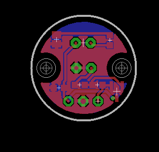
    I've only designed the pcb for the moment, electronics in my thing is air wired, i don't remember how this soldering style is named??
    so this looks like this
    0_1489094889444_20170309_220932.jpg
    i'll check a few things for tomorrow, and also would like to try sensing a few others led colors and i'll post, no problem. I've been able to go up to 110hz though, then it was fluctuating too much (40hz was because i forgot to remove a capa on the signal generator side).


  • Hardware Contributor

    @gohan said in Current Sensing?:

    @Samuel235
    My bet is there isn't one 😄

    @Samuel235 said in Current Sensing?:

    @gohan - I'd be pretty shocked if there was when it was made this quick. Either way, its very nice and a quick turn around.

    rooo i didn't pay attention! So who pay for the bet 😂 but that's gohan which is betting, right 😛

    0_1489095803073_myspulse.png
    So there is one, which should be very low power, afew uA (compared to the 0.4mA min of the lm393), and cheap. I just need to change a few routes, very quick.

    I told you 😉 (i'm kidding of course)


  • Mod

    @scalz
    the PCB is only designed, so it was't actually there inside the sensor, so my bed still stands 😄


  • Hardware Contributor

    ahah, well played 😉


  • Hardware Contributor

    No, you owe us all money! STAND BY YOUR BET! xD

    I like it @scalz - you're approach is much better for low power modes, much better than mine. I see that the comparator is not needed for such application, i'm going that route because its the 'done' way. However, you're style is much better for battery powered nodes which will naturally attract people.

    I'm really struggling to get to grips with KiCAD and i'm starting to give up after just one footprint. This thing would have been hours ago if i just used eagle.

    The style is more 'inline' (not the technical term, but that is how i know it). What photodiode/resistor are you using? Most should pick up quite a decent range of wavelengths on the blinking LED.


  • Hardware Contributor

    @scalz - The general photodiode has a range of "Wavelength range (S10%) 400 nm to 1100 nm (SFH
    213)", quoted from a datasheet here: http://www.osram-os.com/Graphics/XPic5/00101689_0.pdf. So this means that we should be good for a fair few different LED colours.


  • Hardware Contributor

    @scalz - I wouldn't be jealous of me, my school is pretty bad to be honest with you. But it gets me a degree! I'm actually working/studying in the robotics field, so not just electronics 🙂 We have a PCB router at school and I'm trying to get permission to use this for our projects here too, only for prototyping ofc. Finished boards will be ordered from a board house for a more professional feel, but it allows me to get an idea of the size of board we can get our designs down too and such.

    I've also given up with KiCAD for now, it feels so unprofessional to get libraries and such made. Individual addons/programs inside of KiCAD to do different aspects just feels so clunky to me right now, eagle has my attention until i get my hands on solidworks PCB.


  • Hardware Contributor

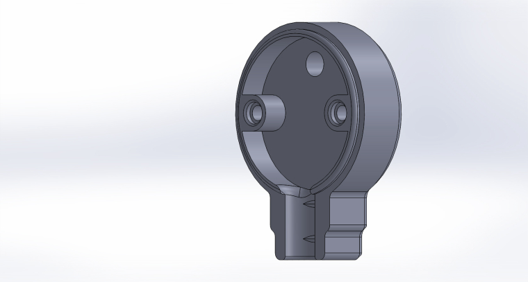
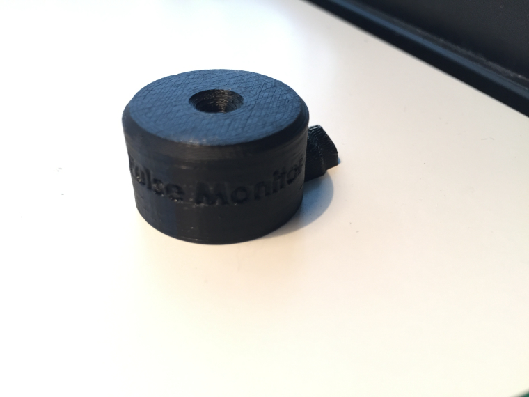
    Here are the renders for my enclosure, will be printing in the morning and will report back with some more progress photos.

    I did try to get the font into the same font as we use for the official logos of MySensors but the font really didn't correspond with solidworks, there are missing faces and lines all over the generated font and therefor it wasn't an option. If anyone knows a work around or something i could do to make it look remotely like the logo then please inform me. At some point i may attempt to put our little man logo on there instead of the opensource hardware logo, maybe.

    I have designed the cable inlet with ethernet cable in mind, that may change too, not sure yet. I'm going for the cheap and locking/latching RJ45 rather than something that could slip out of socket as most of us use our electric cupboards for other uses as well such as cloakrooms for coats and such in the UK.

    0_1489182538397_View1.JPG
    1_1489182538397_View2.JPG
    2_1489182538397_View3.JPG
    3_1489182538397_View4.JPG
    4_1489182538397_View5.JPG
    5_1489182538397_View6.JPG
    6_1489182538397_View7.JPG
    7_1489182538397_View8.JPG

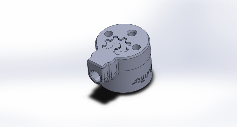
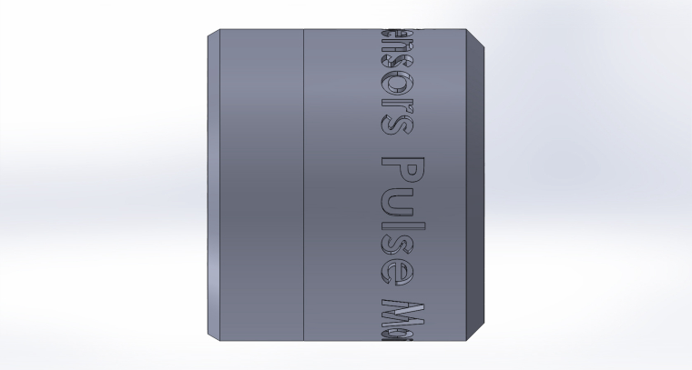
    Would anyone like to see anything on here that i haven't thought about? I'm open to criticism.


  • Hardware Contributor

    cool
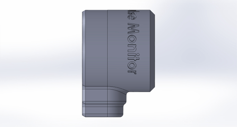
    regarding your print, i think it's better to extrude the text, i'm not sure you'll get a good rendering like this..
    same thing for the logo.. i guess you'll print it facing to the bed, maybe that won't look so great too.


  • Hardware Contributor

    @scalz - I'm not keen on the extruded text look tbh, i'm testing this format but my printer is pretty good with overhangs and thats why i'm taking my chance on the logo on top. It will be facing the bed and so we shall see how it turns out. Its not the end of the world if it doesn't look pretty straight away but i'm hoping its acceptable 🙂


  • Hardware Contributor

    i know for the extruded text, me too though. but i think it's more in general, 3d printing, it is more readable. but you can try, sure it won't take so much time and maybe that'll work, can't wait to see how it looks now 😉


  • Hardware Contributor

    @scalz - I'll print with 0.1mm layer height to give me the best chance possible. They're not meant to be obvious features, they're only small details, 0.5mm indents. So, Fingers crossed.


  • These look great, I have been working on something similar, for now just using an LM393 module with a phototransistor (or it could be a photodiode, I'm not sure). Initial experiments with a light dependent resistor LM393 module were not successful, its ramp up time was too long for what turned out to be the 15ms pulse time on my electricity meter (3200 pulses per kWh).

    At present I am just using Blu-Tack to provide light isolation (my meter is mounted outside on the front porch) but I was looking at a similar enclosure. I have ordered some Velcro dots off eBay for mounting and have been looking at some enclosures but the ones I see here look much better than anything I have found so far.

    @Samuel235 with your design I was thinking it might make more sense mechanically if the wire is hanging down to have it exiting the enclosure as close as possible to the plane of the mounting point so that as much of the force it is exerting is as a shear which Velcro is good at holding.

    I have also ordered some other parts to try replacing the LDR on my original LM393 module, based on a combination of local availability, price, and wavelength and angular sensitivity. The two I choose are the SFH213 photodiode (wide wavelength, 10º angular) and the SFH309 phototransistor (full spectrum, 24º angular). I'm just getting back into electronics after many years so I still have to pull out the soldering iron and get a workbench set up to try these out.


  • Hardware Contributor

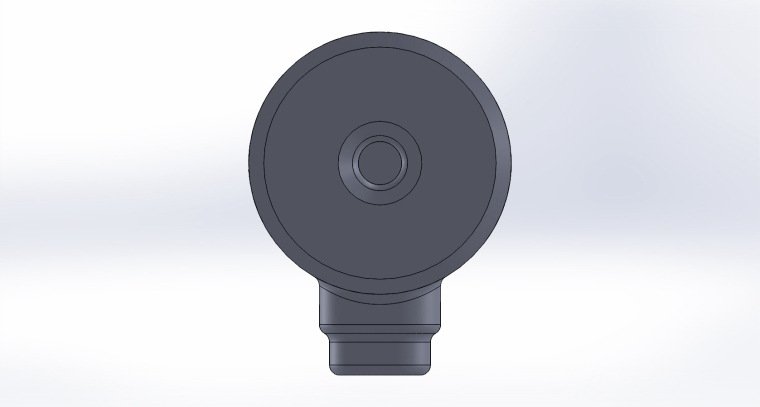
    @mwalker - My design has the cable coming out where it does because that is where the PCB plane is. Mine is relatively thicker than @scalz's, not 100% sure the technical details of his but my detector is not right on the surface, it has a cavity to make it nice and dark for that sensor.

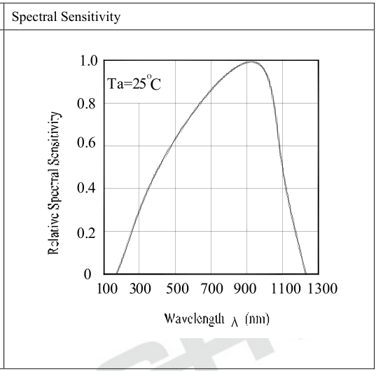
    My design implements a LM393 and a photodiode, which i'm sure you already know, is designed for high speed detections and fast saturation of the diode and fast release back to normal. However, my meter is not one that blinks fast (i think) and i don't have a signal generator at the moment so i wouldn't be able to test down to that speed. The photodiode has an effective window shown below:

    0_1489212238933_wavelength.png

    So, i think that my design may suit your use, lets see 🙂


  • Hardware Contributor

    1_1489219383358_IMG_9145.JPG 0_1489219383356_IMG_9144.JPG

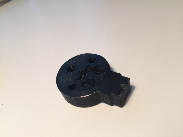
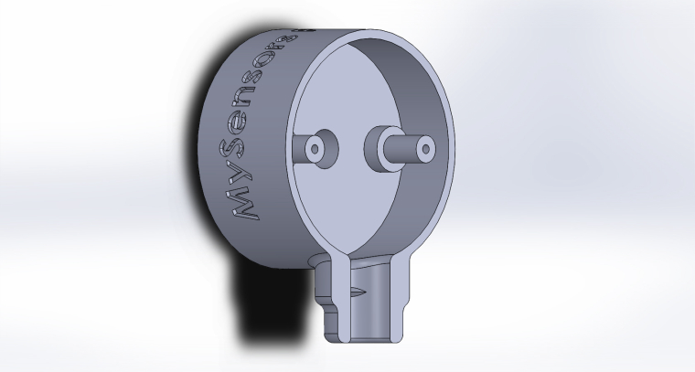
    I'm pretty impressed with how it handeling that overhang on the logo considering there wasn't much vertical space under it to the bed i expected it to droop down to the bed. I like it! Ignore the little cunk out at the cable entry part, my glue held it too hard on the bed. The cable grip is a little too small, reprinting it with a more pronounced grip now (Didn't want it too large as it would damage the cable, but its not enough at the moment).


  • Hardware Contributor

    it didn't slice the text??


  • It looks good @Samuel235, having the detector recessed in a cavity in order to reduce the impact of ambient light isn't something that I had considered, I guess because I was mainly thinking about an off the shelf enclosure, or repurposing some other type of container, i.e. this, but I like these designs a lot better.

    I was able to use a cheap logic analyser with sigrok to work out the pulse time on my meter, and I am in the midst of designing a test rig using WS2812 led strip and a separate microcontroller in order to be able to test my pulse detection code when more of the LM393 modules arrive. One location I need to use this system has ten meters, and another has nine meters, so I need to have a good test rig to make sure that my system won't be dropping pulses.


  • Hardware Contributor

    1_1489229977213_IMG_9148.JPG 0_1489229977212_IMG_9147.JPG

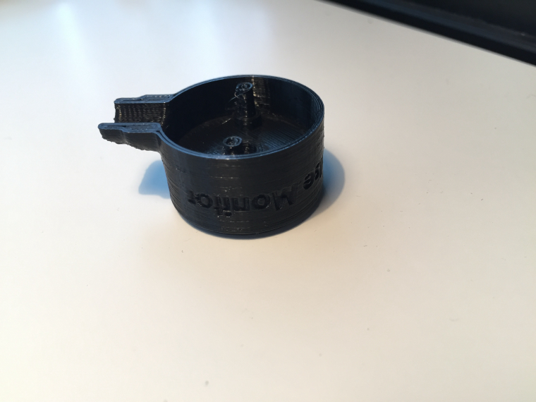
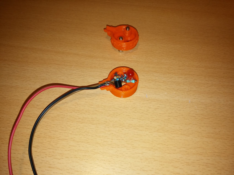
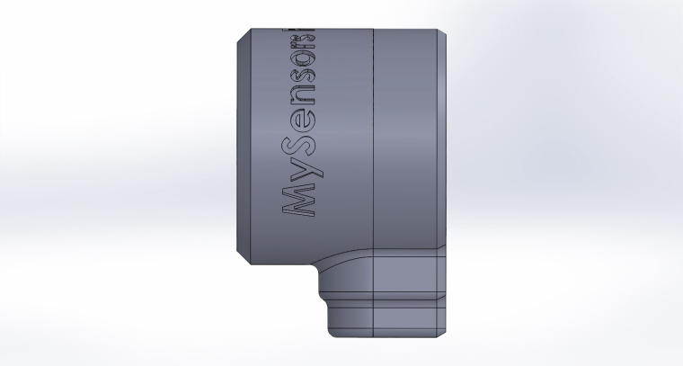
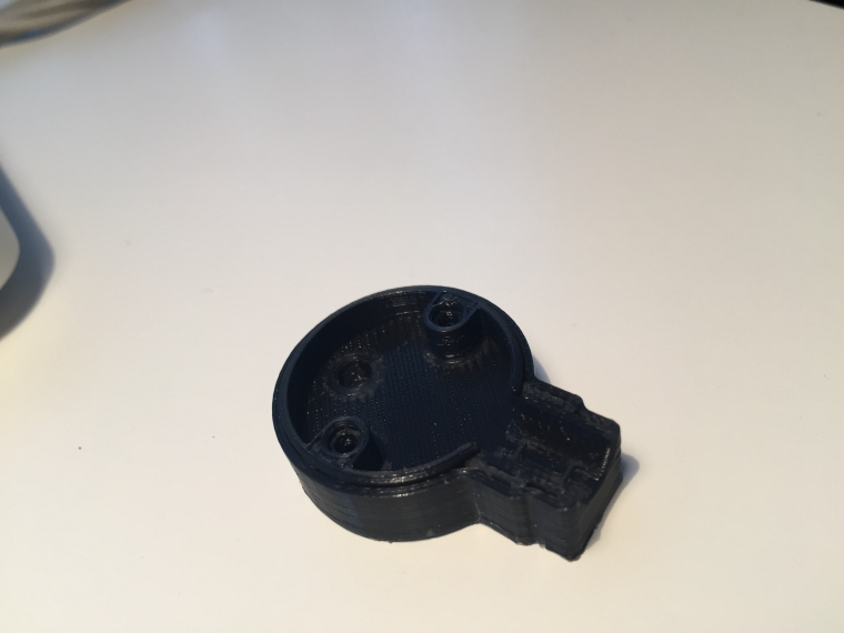
    This is the bottom @scalz, the previous post was of the top part.

    Yes, having the diode resessed was big importance in my eyes. Where do you live as if its not that bad we could print some for you and send to you if you wanted it after it was finished.

    I have a few little tweeks to do but i'm pretty pleased with how the details have turned out.

    Things to ammend:

    1. Change cable specs if i decide on using 4 core into a rj11 connector.
    2. Sort out screw holes as they need some more plastic inside to be more substantial to receive my self-tapping screws.
    3. Make walls slightly thicker to allow for another skin.

  • Mod

    rj11 connector would be very nice to have 🙂


  • Hardware Contributor

    @gohan - I'm thinking either a 4p4c variant or some other board connector. If you could choose any board connector for this use then what would you prefer? Molex JST, dupont, RJ45/RJ11, 3.5mm headphone, 2.5mm headphone, USB mini/micro, anything. What would your preference be? I was only thinking RJ because it locks into place and is hard to pull out if knocked or anything.


  • Hardware Contributor

    @Samuel235 yep screw holes are a bit tight but it looks good 😉 I did a mini tunnel too on mine for isolating a bit the sensor, i think this can help, but not sure as it also increases the distance between the blinking led, but should work.
    For the connector on my side i don't really care 🙂 or rj11/45 maybe..


  • Mod

    @Samuel235
    IMHO rj11 is good because as you said it locks in place, it is not easily mistaken for whatever use, you can make a cable with rj11 plug very quickly (if you have the tool ofc). On the other hand I don't know how hard it would be to make the female socket fit in the 3D printed housing or in any sensor box where the arduino will be placed.


  • Hardware Contributor

    As i would be making the arduino side as a custom board, then i will be able to just put a footprint onto the PCB, not an issue in that respect 🙂


  • Mod

    I am more into IT stuff, 3D modeling/printing and PCB design are still unknown subjects for me 😄


  • @Samuel235 I'm a fair way away from anywhere in Australia, so it may not be worth it, but thank you.

    For connectors I have been leaning towards them being captive on the sensor end, I was looking at RJ45 for the other end, if only because I thought I could repurpose the connector bank and case from a cheap or surplus hub/switch/router.


  • Hardware Contributor

    @mwalker - Ahh okay, no worries.

    Thats makes sense for a one off for yourself, if it is just a one off then i would just wait for us to finished the pcb design and get them made up then you could just cut the connector off the end and add dupont connectors or something and push onto arduino. Unless you're waiting for the finished product with the custom arduino board too.


  • Yes, I imagine a requirement to monitor 9 or 10 separate meters at a single location is a bit of a one off, but I'll be definitely interested in what you come up with to see if I can utilise it. I expect I will be using an ESP8266 based board for the micro controller part as power supply is not an issue, and I have wifi available.

    While researching bits and pieces across the internet I came across:

    https://openenergymonitor.org/forum-archive/node/10707.html

    which I thought may be of interest. It seems they are flashing the LED from a microcontroller output, which is an interesting way of proving that the overall system is working.


  • Hardware Contributor

    @mwalker - Okay, well at that quantity you may find it useful to get some PCBs ordered that i design and then put it in a enclosure that you can come up with (saving shipping costs from me to you). Unless you just directly copy my circuitry to your own solution, up to you! So yeah, if you wanted to use my circuitry you would just wire the three wires into the arduino rather than using a RJ11 connector, would be easier than making a enclosure with panel mounted jacks and stuff. Its much easier for me to use RJ11 connectors as i'm making the arduino side as a custom board too.

    That is what i would call a backward solution. I do agree that it would allow you to see that the arduino is running, but its just not really the way i'm doing this. The LED that i will be blinking on the front of the module is being triggered by the Photodiode and comparator itself, nothing to do with the arduino (this way if someone needed to come to your meter, they can see the LED even if the arduino has failed, as long as its still getting its power. This is not really a design feature though, just a bi-product of how i've made it).


  • @Samuel235 sounds good.

    More digging identified the openenergymonitor sensor is a rebadged unit manufactured in China:

    https://community.openenergymonitor.org/t/directly-connecting-to-optical-pulse-counter-with-rpi/1294/2

    The link doesn't work but it is in the Internet archive, they have a (fuzzy) photo of the internals at right at the bottom:

    http://web.archive.org/web/20160819224835/https://openenergymonitor.org/emon/opticalpulsesensor


  • Hardware Contributor

    @mwalker - Same image as i found on one of the links above. They are not choosing to go the comparator method either. I will be interested to see how fast mine could detect pulses. I might take one into University/school and get the pulse/wave generator on it.


  • Hardware Contributor

    @Samuel235
    i don't think you need to go very high freq though, even with 50hz i think you can cover almost all meters you would need.

    Because 50hz would allow 50*3600= 180000 pulses/hour so if you say you go up to 20kw/h which is a lot! that would be 9000pulses/kw/h. So 100hz with a photores is a lot..

    but sure photodiode could be useful maybe for some other usecase, i don't know..or for some data transmission lol but here it's more something like "dark or light" at "slow rate".

    in case you have parts in stock and want to play, you still can use 3,4 resistors, cheap bs250 mosfet and photoresistor, very easy to use. My files are now uploaded at openhardware if you need https://forum.mysensors.org/topic/6430/mypulse-sensor

    Another nice article about photoresistor and blinking led detection i've just discovered. Looks like i've decided to use a mosfet for switching and perhaps a better digital level.., thus saving the footprint size + cost of the potentiometer.
    http://jeelabs.org/2012/03/18/detecting-a-blinking-led/


  • Hardware Contributor

    @scalz - I made it with a comparator for two main reasons:

    1. I wasn't sure how much the frequency fluctuated from country to country and instead of spending days on end doing research for that, I just chose to go safe rather than sorry.
    2. If there is another application that we're not thinking of that would take advantage of a fast/high frequency light detector, this would fit perfectly.

    Thanks for uploading the files, will check them out today, although i pretty much have mine done now, just not got the design penalised onto the PCB to get 4 out of the 50x50 prototype order.

    I will get it made at University to test the board too.


  • @scalz the jeelabs post is interesting. When I was using an LM393 module with a LDR I was unable to detect the pulses coming from my meter (later established as 15ms). Reading that article it seems that was because of inadequate light proofing (the meter is shaded, but outdoors), but lacking any sort of test equipment, it's interesting to see his oscilloscope tracings of the response of the LDR to a pulse. Thanks for linking it.


  • I have a Smappee energy monitor, it's connected to the main input and "detect" the different equipments. It's good to monitor the overall energy consumption and production if you have solar pannels but it's not able to detect everything.
    In summary, it can tell you the consumption of anything with a resistor (electric oven, motor, cofee machine) or a motor (roller shutter, pump,...) but for electronic, PC and other things for which the power consumption is not regular it won't help you much. For this, I think monitoring individual component will be the best.

    But as you probably plus a pwoer meter on each plug, maybe a combintation of both will be a good choice.


  • I use main line snap on current sensors for whole house monitoring, and snap on or hall effect sensors for specific device monitoring when necessary. I use current shunts for high current, low voltage dc monitoring like battery backup or off grid solar power systems.


  • Mod

    @sspence65
    but that way you can only monitor current, not actual power used


  • I also monitor the voltage (9v transformer and voltage divider) so I am getting current & voltage, and also time, so I can monitor KWh not just KW.


  • @sspence65
    I think too that your method for power metering is better then calculating it from "blinks" of LED of power meter.
    That is good for energy consumption only by counting pulses.
    You can send correct power consumption in each time, which is not possible from blinks.
    And I think in most cases we can assume stable voltage in the power net, so we do not need measure voltage.


  • Hardware Contributor

    I have just posted my solution so far:

    Forum thread: https://forum.mysensors.org/topic/6460/homini-pulse-meter-monitor
    Openhardware.io: https://www.openhardware.io/view/356/Homini-Pulse-Meter-Monitor#tabs-comments

    The sensor part is designed, currently working on the custom microcontroller board - You're more than welcome to use an arduino or any other solution for a microcontroller module.


  • Mod

    @kimot
    Actually counting pulses takes advantage of the supposedly accurate measurements of the main power meter instead of making your own. In addition from a safety perspective the less people work directly with 220v, the better.
    IMHO assuming stable voltage it's not correct as it actually fluctuates even over 20V


  • @gohan
    Yes, pulse counting is best for energy consumption ( kWh ), but is inapplicable for actual power
    ( W ) consumption measuring.


  • Mod

    @kimot
    It depends on the meter: the one we have have 2 LEDs one is for W and the other kWh


  • @gohan
    Can you describe function of LED for watt metering, please?
    I hear about this first time, so I am interested.


  • Mod

    Sorry i messed up the units, the first LED is 1 pulse for 1 Wh the other measures VARh


  • @gohan
    Thanks for info.


Log in to reply
 

Suggested Topics

  • 87
  • 2
  • 1
  • 5
  • 10
  • 8

1
Online

11.2k
Users

11.1k
Topics

112.5k
Posts