Vera Plus and ESP8266
-
@korttoma said in Vera Plus and ESP8266:
@djzang do you have the following line in your sketch?
#define MY_INCLUSION_MODE_FEATUREYes I do.... here is my full sketch:
/**
 * The MySensors Arduino library handles the wireless radio link and protocol
 * between your home built sensors/actuators and HA controller of choice.
 * The sensors forms a self healing radio network with optional repeaters. Each
 * repeater and gateway builds a routing tables in EEPROM which keeps track of the
 * network topology allowing messages to be routed to nodes.
 *
 * Created by Henrik Ekblad <henrik.ekblad@mysensors.org>
 * Copyright (C) 2013-2015 Sensnology AB
 * Full contributor list: https://github.com/mysensors/Arduino/graphs/contributors
 *
 * Documentation: http://www.mysensors.org
 * Support Forum: http://forum.mysensors.org
 *
 * This program is free software; you can redistribute it and/or
 * modify it under the terms of the GNU General Public License
 * version 2 as published by the Free Software Foundation.
 *
 *******************************
 *
 * REVISION HISTORY
 * Version 1.0 - Henrik EKblad
 * Contribution by a-lurker and Anticimex,
 * Contribution by Norbert Truchsess <norbert.truchsess@t-online.de>
 * Contribution by Ivo Pullens (ESP8266 support)
 *
 * DESCRIPTION
 * The EthernetGateway sends data received from sensors to the WiFi link.
 * The gateway also accepts input on ethernet interface, which is then sent out to the radio network.
 *
 * VERA CONFIGURATION:
 * Enter "ip-number:port" in the ip-field of the Arduino GW device. This will temporarily override any serial configuration for the Vera plugin.
 * E.g. If you want to use the defualt values in this sketch enter: 192.168.178.66:5003
 *
 * LED purposes:
 * - To use the feature, uncomment any of the MY_DEFAULT_xx_LED_PINs in your sketch, only the LEDs that is defined is used.
 * - RX (green) - blink fast on radio message recieved. In inclusion mode will blink fast only on presentation recieved
 * - TX (yellow) - blink fast on radio message transmitted. In inclusion mode will blink slowly
 * - ERR (red) - fast blink on error during transmission error or recieve crc error
 *
 * See http://www.mysensors.org/build/esp8266_gateway for wiring instructions.
 * nRF24L01+  ESP8266
 * VCC        VCC
 * CE         GPIO4
 * CSN/CS     GPIO15
 * SCK        GPIO14
 * MISO       GPIO12
 * MOSI       GPIO13
 * GND        GND
 *
 * Not all ESP8266 modules have all pins available on their external interface.
 * This code has been tested on an ESP-12 module.
 * The ESP8266 requires a certain pin configuration to download code, and another one to run code:
 * - Connect REST (reset) via 10K pullup resistor to VCC, and via switch to GND ('reset switch')
 * - Connect GPIO15 via 10K pulldown resistor to GND
 * - Connect CH_PD via 10K resistor to VCC
 * - Connect GPIO2 via 10K resistor to VCC
 * - Connect GPIO0 via 10K resistor to VCC, and via switch to GND ('bootload switch')
 *
  * Inclusion mode button:
 * - Connect GPIO5 via switch to GND ('inclusion switch')
 *
 * Hardware SHA204 signing is currently not supported!
 *
 * Make sure to fill in your ssid and WiFi password below for ssid & pass.
 */


// Enable debug prints to serial monitor
#define MY_DEBUG

// Use a bit lower baudrate for serial prints on ESP8266 than default in MyConfig.h
#define MY_BAUD_RATE 9600

// Enables and select radio type (if attached)
//#define MY_RADIO_NRF24
//#define MY_RADIO_RFM69

#define MY_GATEWAY_ESP8266

#define MY_ESP8266_SSID "myssid"
#define MY_ESP8266_PASSWORD "mypassword"

// Enable UDP communication
//#define MY_USE_UDP

// Set the hostname for the WiFi Client. This is the hostname
// it will pass to the DHCP server if not static.
#define MY_ESP8266_HOSTNAME "esp01"

// Enable MY_IP_ADDRESS here if you want a static ip address (no DHCP)
//#define MY_IP_ADDRESS 192,168,178,87

// If using static ip you need to define Gateway and Subnet address as well
//#define MY_IP_GATEWAY_ADDRESS 192,168,178,1
//#define MY_IP_SUBNET_ADDRESS 255,255,255,0

// The port to keep open on node server mode
#define MY_PORT 5003

// How many clients should be able to connect to this gateway (default 1)
#define MY_GATEWAY_MAX_CLIENTS 2

// Controller ip address. Enables client mode (default is "server" mode).
// Also enable this if MY_USE_UDP is used and you want sensor data sent somewhere.
//#define MY_CONTROLLER_IP_ADDRESS 192, 168, 178, 68

// Enable inclusion mode
#define MY_INCLUSION_MODE_FEATURE

// Enable Inclusion mode button on gateway
// #define MY_INCLUSION_BUTTON_FEATURE
// Set inclusion mode duration (in seconds)
//#define MY_INCLUSION_MODE_DURATION 60
// Digital pin used for inclusion mode button
//#define MY_INCLUSION_MODE_BUTTON_PIN  3


// Set blinking period
// #define MY_DEFAULT_LED_BLINK_PERIOD 300

// Flash leds on rx/tx/err
// Led pins used if blinking feature is enabled above
#define MY_DEFAULT_ERR_LED_PIN 16  // Error led pin
#define MY_DEFAULT_RX_LED_PIN  16  // Receive led pin
#define MY_DEFAULT_TX_LED_PIN  16  // the PCB, on board LED

#if defined(MY_USE_UDP)
#include <WiFiUdp.h>
#endif

#include <ESP8266WiFi.h>

#include <MySensors.h>

#include "DHT.h"
#define DHTTYPE DHT22
const int DHTPin = 2;
DHT dht(DHTPin, DHTTYPE);
#define CHILD_ID_HUM 0
#define CHILD_ID_TEMP 1
MyMessage msgHum(CHILD_ID_HUM, V_HUM);
MyMessage msgTemp(CHILD_ID_TEMP, V_TEMP);
static char celsiusTemp[7];
static char humidityTemp[7];

void setup()
{
delay(10);
dht.begin();
}

void presentation()
{
	sendSketchInfo("TemperatureAndHumidity", "1.1");
  present(CHILD_ID_HUM, S_HUM);
  present(CHILD_ID_TEMP, S_TEMP);
}


void loop()
{
	float h = dht.readHumidity();
  float t = dht.readTemperature();
  if (isnan(h) || isnan(t)) {
              Serial.println("Failed to read from DHT sensor!");
              strcpy(celsiusTemp,"Failed");
              strcpy(humidityTemp, "Failed");
            }
            else{
              dtostrf(t, 6, 2, celsiusTemp);
              dtostrf(h, 6, 2, humidityTemp);
              // You can delete the following Serial.print's, it's just for debugging purposes
              Serial.print("Humidity: ");
              Serial.print(h);
              Serial.print(" %\t Temperature: ");
              Serial.print(t);
              Serial.println(" *C ");
              send(msgTemp.set(t, 1));
              send(msgHum.set(h, 1));
            }
  delay(15000);
}
When I clock on "start" inclusion in the Vera plugin, it scans but always says 0 devices found. I haven't setup an inclusion button on my GW. I figured that wasn't necessary if the GW was the sensor?
-
@djzang don't use delay() in your sketch please chang it to wait(). Your GW will not receive the presentation command when it is in "delay".
@korttoma said in Vera Plus and ESP8266:
@djzang don't use delay() in your sketch please chang it to wait(). Your GW will not receive the presentation command when it is in "delay".
I switched delay() to wait() but I'm still seeing the same behavior. When i click on "start" the inclusion process it always returns 0 devices found. There must be something that I'm missing. It seems like the way I'm doing things is not what most are doing, but from what I've ready it should be possible. Since my GW IS the sensor I can't simply power cycle the sensor node to have the GW pick it up during inclusion. Is there something else I should be doing instead?
-
I must not be doing the inclusion correctly in my sketch or in general as I see this in the Vera logs:
08 03/19/17 10:20:56.071 JobHandler_LuaUPnP::HandleActionRequest device: 36 service: urn:upnp-arduino-cc:serviceId:arduino1 action: StartInclusion <0x74d9d520> 08 03/19/17 10:20:56.072 JobHandler_LuaUPnP::HandleActionRequest argument DeviceNum=36 <0x74d9d520> 08 03/19/17 10:20:56.072 JobHandler_LuaUPnP::HandleActionRequest argument serviceId=urn:upnp-arduino-cc:serviceId:arduino1 <0x74d9d520> 08 03/19/17 10:20:56.072 JobHandler_LuaUPnP::HandleActionRequest argument action=StartInclusion <0x74d9d520> 50 03/19/17 10:20:56.073 luup_log:36: Arduino: Sending: 0;0;3;0;5;1 <0x77e42320> 04 03/19/17 10:20:56.078 <Job ID="14" Name="" Device="36" Created="2017-03-19 10:20:56" Started="2017-03-19 10:20:56" Completed="2017-03-19 10:20:56" Duration="0.5062000" Runtime="0.4342000" Status="Successful" LastNote=""/> <0x77e42320> 50 03/19/17 10:20:56.118 luup_log:36: Arduino: urn:upnp-arduino-cc:serviceId:arduino1,InclusionMode, 1, 36 <0x73b3d520> 06 03/19/17 10:20:56.119 Device_Variable::m_szValue_set device: 36 service: urn:upnp-arduino-cc:serviceId:arduino1 variable: InclusionMode was: 0 now: 1 #hooks: 0 upnp: 0 skip: 0 v:0xa920d0/NONE duplicate:0 <0x73b3d520> 50 03/19/17 10:20:56.119 luup_log:36: Arduino: urn:upnp-arduino-cc:serviceId:arduino1,InclusionFoundCountHR, 0 devices found, 36 <0x73b3d520> 06 03/19/17 10:20:56.120 Device_Variable::m_szValue_set device: 36 service: urn:upnp-arduino-cc:serviceId:arduino1 variable: InclusionFoundCountHR was: now: 0 devices found #hooks: 0 upnp: 0 skip: 0 v:(nil)/NONE duplicate:0 <0x73b3d520>``` -
Maybe you could try commenting out everything in the loop() function to rule out this being the problem.
And if you have not already tried then reboot and/or restart luup for your Vera.
-
@r-nox said in Vera Plus and ESP8266:
#define MY_INCLUSION_MODE_DURATION 60
I uncommented out the above line and tested.... it keeps saying 0 devices found. I also tried removing everything under loop() as well and i get the same behavior.
06      03/20/17 20:24:35.616   Device_Variable::m_szValue_set device: 39 service: urn:upnp-arduino-cc:serviceId:arduino1 variable: InclusionMode was: 0 now: 1 #hooks: 0 upnp: 0 skip: 0 v:0xfc3e10/NONE duplicate:0 <0x73ce5520>
50      03/20/17 20:24:35.616   luup_log:39: Arduino: urn:upnp-arduino-cc:serviceId:arduino1,InclusionFoundCountHR, 0 devices found, 39 <0x73ce5520>
06      03/20/17 20:24:35.616   Device_Variable::m_szValue_set device: 39 service: urn:upnp-arduino-cc:serviceId:arduino1 variable: InclusionFoundCountHR was:  now: 0 devices found #hooks: 0 upnp: 0 skip: 0 v:(nil)/NONE duplicate:0 <0x73ce5520>
50      03/20/17 20:25:35.599   luup_log:39: Arduino: urn:upnp-arduino-cc:serviceId:arduino1,InclusionMode, 0, 39 <0x73ce5520>
06      03/20/17 20:25:35.599   Device_Variable::m_szValue_set device: 39 service: urn:upnp-arduino-cc:serviceId:arduino1 variable: InclusionMode was: 1 now: 0 #hooks: 0 upnp: 0 skip: 0 v:0xfc3e10/NONE duplicate:0 <0x73ce5520>
50      03/20/17 20:25:35.610   luup_log:39: Arduino: urn:upnp-arduino-cc:serviceId:arduino1,InclusionFoundCountHR, , 39 <0x73ce5520>
06      03/20/17 20:25:35.610   Device_Variable::m_szValue_set device: 39 service: urn:upnp-arduino-cc:serviceId:arduino1 variable: InclusionFoundCountHR was: 0 devices found now:  #hooks: 0 upnp: 0 skip: 0 v:(nil)/NONE duplicate:0 <0x73ce5520>
50      03/20/17 20:25:35.611   luup_log:39: Arduino: Inclusion mode ended. <0x73ce5520>
and this is what i see in the serial monitor of the gateway:
0;255;3;0;9;MCO:BGN:STP 0;255;3;0;9;MCO:REG:NOT NEEDED 0;255;3;0;9;MCO:BGN:INIT OK,TSP=NA pm open,type:2 0 0;255;3;0;9;Client 0 connected 0;255;3;0;9;Client 0: 0;0;3;0;2;Get Version 0;255;3;0;9;Client 0: 0;255;3;0;9;Client 0: 0;0;3;0;5;1 0;255;3;0;9;Client 0: 0;255;3;0;9;Client 0: 0;0;3;0;5;1 0;255;3;0;9;Client 0: -
Hello djzang
I just built the serial gw using esp-8266 but can not find how to physically hook it to Vera Plus or Vera 3 , do you have step by step instruction as how to do that maybe with pictures and what setup you entered in to the serial port configuration?
Thanks -
Hello djzang
I just built the serial gw using esp-8266 but can not find how to physically hook it to Vera Plus or Vera 3 , do you have step by step instruction as how to do that maybe with pictures and what setup you entered in to the serial port configuration?
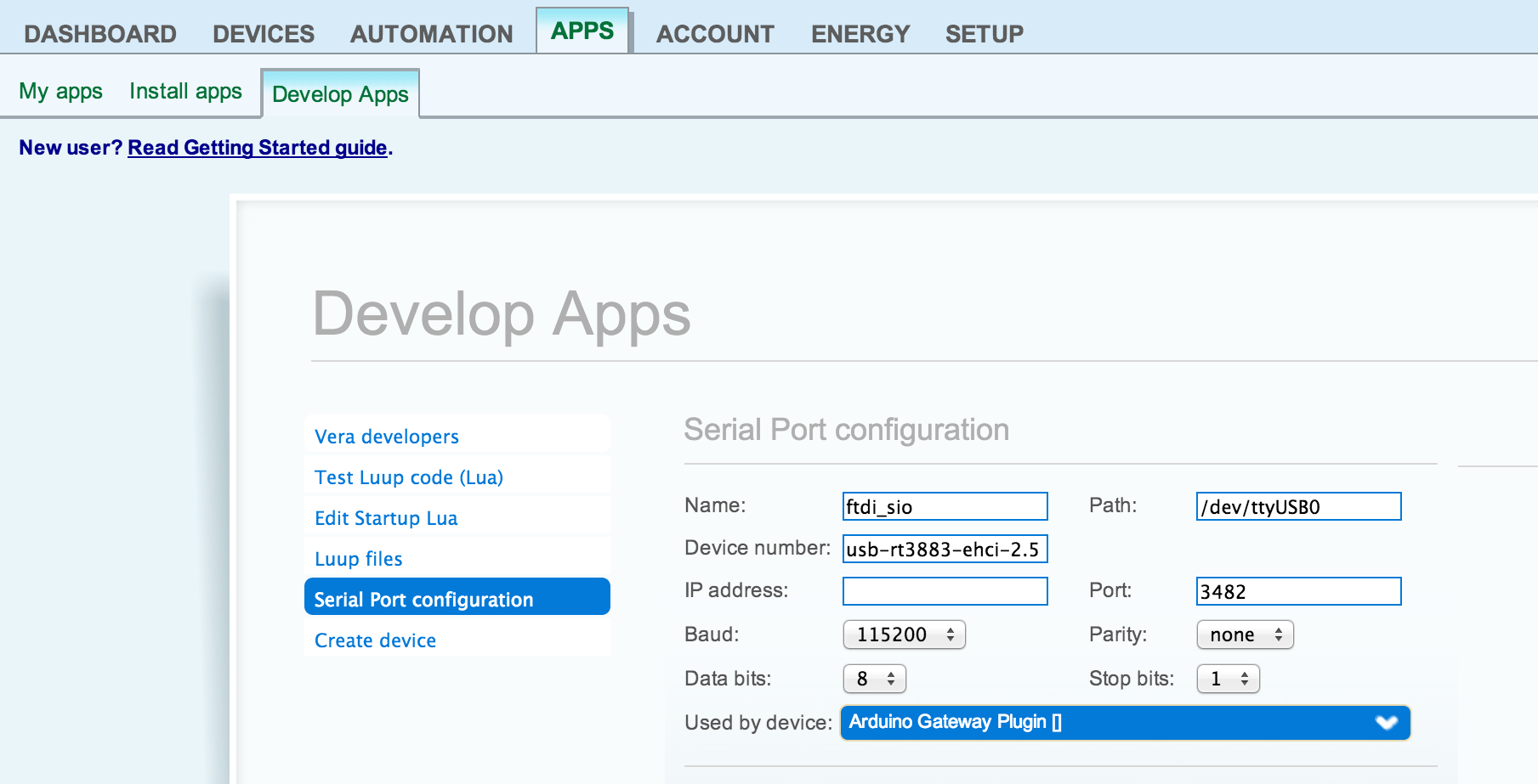
Thanks@mntlvr I'm not sure what kind of serial chip is on the ESP8266 but Vera can not detect all types of serial chips because there are no drivers installed. FTDI chips should be detected by Vera automatically and then you just need to set the correct serial port settings:
-
So do you have a working serial general on your Vera now and does it use an ESP 8266 or a Arduino Nano
-
@mntlvr The Vera controllers have a list of supported serial devices. If you look at this page under USB Serial Devices, looking at the chipset column you will see that the FTDI and PL2303 chipsets are the only ones that Vera natively supports. For the 2303 chipsets, some say that they don't work, and others say that manual configuration is needed. Mine luckily just worked with no extra configuration. That list was last modified in 2013 though, so what is supported/works and what doesn't most likely has changed since then.
-
Okay thanks
Well I built a Ethernet board using 1.4.1 library and a W5100 Ethernet board and it worked right off so now I am as curious as heck to make the ESP 8266 work but I still think it has something to do with the newest library. I think I will start out with the Arduino IDE 1.6.4 or something like that and see if that makes a difference. Not very many on this site can help with the issue because they do not have Vera Controllers, so I have to figure this out and just keep trying