MySensors weather station


  • @Yveaux You can NEVER forget the WAF. Luckily, my wife is to the point of just asking, "so what are you building now".


  • @DavidZH Good point. Reversing these should not be a big problem. Just a matter of re-designing the internal rotors that hold the magnets. I'd have to do that because one side has more room than the other. They are only like 15 minute prints anyway

    Thanks for the suggestion.


  • So Monday I should have my new reed switches and should be able to start working on the board for the wind sensors. For the anemometer, the setup is pretty simple. The rotor has a magnet (red arrow) that passes by the reed switch (blue arrow) to count the revolutions.
    0_1492875963522_upload-373e9c0b-f453-4328-97fc-62a7be9b5cc1

    The reed switch wire for the anemometer will pass through the hole at the edge (green arrow) and connect to the direction rotor PCB. Had a small problem when I was cutting the board (blue arrow), but it should still be usable for the prototype. The red lines (red arrow) are where the reed switches will get mounted for the wind direction rotor.
    0_1492876264052_upload-b165feee-93e0-48a9-b1d0-4c2af21c550e

    The direction rotor has a small round magnet (blue arrow) which should face the nose cone of the wind direction vane and will pass by the magnetic reed switches mounted on the round PCB
    0_1492876688706_upload-57ee9f7c-ac97-4704-855f-72e916d8eb07

    The circuit board mounting plate will get sandwiched between the top and bottom covers and have the main connection wire feed through the side hole near the wind direction magnet in the previous pic.
    0_1492877066850_upload-e840a1bf-f9b5-4b42-bfcb-4b18d46d47cf

    Later I will post the proposed schematic for how this will all connect to the pro mini. I will also hopefully have some test code for the setup.


  • So I was playing around a bit on the circuits.io website and came up with this for a test circuit. Each push button switch represents a reed switch for the direction rotor.
    0_1492881263412_upload-beb662b0-043a-4250-aedd-3a51ac3497f1

    The idea is to separate the 8 reed switches into two banks which will only use 2 analog IO lines to handle all 8 switches. The first bank of reed switches will be for North, South, East and West. The second bank will be for Northeast, Southeast, Southwest and Northwest. My main reason for doing it this way was due to the fact that the MySensors library API uses V_DIRECTION for the wind direction and is a number between 0 and 360. I needed a way to get more accurate than just 0, 45, 90, 135, 180 etc... which I could do tying all of the reed switches to 1 analog IO line. With this design, I can catch the directions when the magnet is in-between 2 of the reed switches and activating both giving me another 1/8 step of accuracy.

    Below is the code that I tested on the above circuit. The code should handle debouncing of the reed switches. With the reed switch and magnet rotor setup in place, the code should never reach a 999 value. It should always return a value between 0 and 337 based on the direction of the wind.

    int old_NSEW = 0, old_NeSeSwNw = 0;
    
    void setup() {
      Serial.begin(9600);
      pinMode(A0, INPUT);
      pinMode(A1, INPUT);
    }
    
    int getNSEW()
    {
      int i, z, sum;
      int button;
    
      sum = 0;
      for (i=0; i < 4; i++)
      {
         sum += analogRead(A0);
      }
      z = sum / 4;
      //Serial.println(z);
      if (z > 1021) button = 999;                                           
      else if (z > 357 && z < 361) button = 0;                     
      else if (z > 405 && z < 409) button = 90;                
      else if (z > 467 && z < 471) button = 180;                
      else if (z > 551 && z < 555) button = 270;  
      else button = 999;
    
      return button;
    }
    
    int getNeSeSwNw()
    {
      int i, z, sum;
      int button;
    
      sum = 0;
      for (i=0; i < 4; i++)
      {
         sum += analogRead(A1);
      }
      
      z = sum / 4;
      //Serial.println(z);
      if (z > 1021) button = 999;                                              
      else if (z > 357 && z < 361) button = 45;                     
      else if (z > 405 && z < 409) button = 135;                
      else if (z > 467 && z < 471) button = 225;                
      else if (z > 551 && z < 555) button = 315;  
      else button = 999;
    
      return button;
    }
    
    
    void loop ()
    {
      int NSEW, NeSeSwNw, NSEW_curr, NeSeSwNw_curr, triggered_NSEW, triggered_NeSeSwNw;  
      NSEW = getNSEW(); 
      NeSeSwNw = getNeSeSwNw();
      if (NSEW != old_NSEW)
      {
          delay(50);        // debounce
          NSEW_curr = getNSEW();
    
          if (NSEW == NSEW_curr)
          {
             old_NSEW = NSEW;
             triggered_NSEW = NSEW;
            if (NSEW == 999 || NeSeSwNw == 999) {
               triggered_NSEW = NSEW;
            } else if (NSEW < NeSeSwNw) {
               triggered_NSEW = ((NeSeSwNw - NSEW) / 2) + NSEW;
            } else {
               triggered_NSEW = NSEW - ((NSEW - NeSeSwNw) / 2);
            }
             Serial.println(triggered_NSEW);
          }
       }
      if (NeSeSwNw != old_NeSeSwNw)
      {
          delay(50);        // debounce
          NeSeSwNw_curr = getNeSeSwNw();
    
          if (NeSeSwNw == NeSeSwNw_curr)
          {
             old_NeSeSwNw = NeSeSwNw;
            if (NSEW == 999 || NeSeSwNw == 999) {
               triggered_NeSeSwNw = NeSeSwNw;
            } else if (NSEW < NeSeSwNw) {
               triggered_NeSeSwNw = ((NeSeSwNw - NSEW) / 2) + NeSeSwNw;
            } else {
               triggered_NeSeSwNw = NeSeSwNw - ((NSEW - NeSeSwNw) / 2);
            }
            Serial.println(triggered_NeSeSwNw);
          }
       }
    }
    

    Does anyone see any issues in this approach to the wind direction?

    Next I plan on working on the code for the anemometer to calculate wind speed. I could possibly have that figured out later today.


  • Mod

    Personally I think you may have issues with the position when magnet will be around the middle of 2 sensors because it could either trigger both or none of them so magnet strength will be crucial to your setup. I still think the optical sensor used by the other weather stations is a preferred solution


  • @gohan the diameter of the circuit board is 52mm or a radius of 26mm. From the center of the shaft to the center of the magnet is 17.75mm. The reed switches I ordered were 7mm long. I had to get shorter ones because of the tight space they will be in. The magnet's diameter is 4.25mm and it is a pretty strong neodymium magnet. Calculating the circumference to the center of where the magnet is mounted on the rotor, that is 111.5mm. Dividing that by 8 gives a distance between the reed switches of 13.94mm. I tested with a different reed switch that I had and found that the detection distance from magnet to reed switch is roughly 5mm plus or minus a smidge. The rotor should be fairly close to the reed switches if my calculations are correct. I can't say 100% till I get the reed switches and build the assembly, but I think I am going to be fine. I think worst case, I might have to get a slightly larger magnet, and even if I did it wouldn't have to be more than 1 to 2 millimeters bigger than the one I have.


  • So here is an update on where I am at with the direction rotor assembly. I came up with the following proposed circuit board assembly based on my circuits.io layout from my previous post. All of the reed switches are in a circular configuration and alternate the 2 different switch banks seen in the above post.
    0_1493175374379_upload-a0192f97-d885-4f50-b4cd-9f01ec151da7

    Following that diagram, here is the final prototype board. The only difference in the final board is that I used 3.3k resistors, as I was low on 2.2k's. I figured all I should have to do is make a couple adjustments to the code for the derived values when a reed switch was activated.
    0_1493175842348_upload-46ddb478-2a46-4b59-88fa-6a290eec5272

    Even though the design seemed pretty solid, I seem to be having some issues with it. I have tried a few different rotor and magnet assemblies. All of the magnets are neodymium magnets that I got from various salvage operations. The order from left to right is the order that I tested them in.
    0_1493176935322_upload-3b93081d-dd79-412c-b882-e6327d927e4b

    It appears that @gohan was correct about the first test rotor. Some of the other ones just seemed a bit erratic. There are a couple other things that I want to try, but I'm starting to look at some kind of 360 degree angle sensor to potentially use. I am wondering if anyone in the forum has done any kind of rotational angle sensing, and what sensor did you end up using?


  • Admin

    @dbemowsk

    Maybe you can get some inspiration from this (that's using a potentiometer)
    http://www.thingiverse.com/thing:952978


  • Mod

    20$ for a potentiometer???? 🙀
    With that price it is cheaper to hack a spare part from another weather station 😄


  • Admin

    Haha.. yes.. didn't google prices. That's pricey 😬


  • Mod

    @dbemowsk You could use a compass sensor (e.g. HMC5883L) with a small magnet revolving above it.
    Requires some math to get the angle but once you nail it you'll get incredible precision from it.


  • Mod

    I still think the central LED with 8 phototransistor around is the cheapest solution 🙂 (given that you are already 3D printing everything, I don't think one more part will make much difference; there is one example in another topic about hacking a weather station)


  • @gohan I am assuming that you are talking about this post:
    https://forum.mysensors.org/topic/6645/fody-weather-station-wind-sensor/2

    I would have to figure out how to wire everything, but that would be an option.


  • Mod

    I was referring exactly to that topic. Maybe you could ask Flopp if he could measure his part for you. The tricky part will be to find the right brightness for the LED when it is crossing between 2 phototransistor, but I think it will be easier to adjust than changing a magnetic field 🙂
    About those parts, I can't say much, it is up to you: with 10 you still have 2 as spares just in case, 50 are quite a lot unless you plan to build more for your friends 🙂


  • @gohan Good point on the 50 pieces. I can do some experimenting prior to the final design to figure out what is going to work best.


  • Mod

    keep in mind that if you don't have a regulated voltage, the LED may change brightness as battery drains out. It just came to my mind: can you manage on the sw side 2 of your reed switches on at the same time? If you can find a way you can still use the magnet and add additional "half step" in your wind direction and make it more precise


  • @gohan My plan I think is going to be to have a solar panel that will charge a small LiPo or SLA battery. I would size the battery big enough to handle the regulator on the pro mini and use the regulated output voltage to run the LED to give it a constant brightness.

    My original plan with the reed switches was to have the ability to trigger 2 reed switches at once. That was the reason for having 4 reed switches for N S E W and the other 4 for NE SE SW NW. I designed it to use 2 IO lines for the 2 different banks of 4 reed switches. That way if the N and NE reed switches were triggered that you would get that extra half step. The biggest problem that I am running into is that for some reason the reed switches don't seem to be triggering consistently with any of the magnet configurations I have tried. That is why I wanted to look at another approach.

    I ordered the 10 photo transistors this morning. I will still look at a way to run them as 2 banks of 4 sensors like I did with the reed switches so I can get that extra half step.


  • @gohan said in MySensors weather station:

    The tricky part will be to find the right brightness for the LED when it is crossing between 2 photo-transistor, but I think it will be easier to adjust than changing a magnetic field 🙂

    What I did for wind direction is that I "look" for the first photo-transistor that get light from the LED and use that direction. So I don't care if the light is crossing between 2 photo-transistor. I scan from first digital in until i scanned all of them.

    void readWindDirection()
    {
      //check in what direction the wind is. First sensor that have light will be the direction
      int i = 4;
      for (i; i < 9 ; i++){
        if (!digitalRead(i)){
          WD = WDarray[i-4];
          return;
        }
      }
      i = 14;
      for (i; i < 17 ; i++){
        if (!digitalRead(i)){
          WD = WDarray[i-9];
          return;
        }
      }
    }


  • @flopp I am curious how you wired your electronics. I saw that as one of your original questions in your fody weather station post. so based on what you are saying, you really only use the 8 different directions, N, NE, E, SE, S, SW, W, NW, correct?

    I have the basic design of the one you had pictured in your post mostly done. I still have to plan for circuit board mounting and wire connections, but I don't think that should be too difficult.

    Here is my starting design done in OpenSCAD. I have the center hole threaded part way with a US 1/4 x 20 thread as that is what I used for the bolts to go through the wind vane.
    0_1493275410728_upload-206e872f-5ef5-4ef8-9c8b-5e4536d8fb31
    0_1493275543341_upload-febb1225-6256-4cc2-bee9-2c4d220d3238

    I shoud be getting the phototransistors by Monday, so I want to draw up a preliminary design for the circuit board before that.


  • @dbemowsk said in MySensors weather station:

    @flopp I am curious how you wired your electronics. I saw that as one of your original questions in your fody weather station post. so based on what you are saying, you really only use the 8 different directions, N, NE, E, SE, S, SW, W, NW, correct?

    Yes, correct. I have 8 receivers for the light.

    I want to know more about this product https://www.youtube.com/watch?v=-oQiJ50LcAc


  • @dbemowsk said in MySensors weather station:

    Here is my starting design done in OpenSCAD. I have the center hole threaded part way with a US 1/4 x 20 thread as that is what I used for the bolts to go through the wind vane.

    Your drawings look good.


  • Here is possibly how it would be fitted into the wind vane body cap. It'll be a tight fit for the PCB, but I'm sure I can make it.
    0_1493290462764_upload-41341d20-831d-4331-9aba-56d34034fbb9


  • Some things about the direction sensor, your magnet/reed switch is exactly what is in the old dallas 1-wire weather station and it worked well giving 16 positions,

    the led/photodiode method mentioed by gohan is interesting, if you used analog inputs you could use the value across 3 of them at a time to interpolate a pretty high resolution answer, multiplexing could make it so you dont need 8 analog inputs.

    Another thing is a rotary encoder, ive seen them used to measure the angles of telescope mounts, i believe they can be had with good enough resolution for your needs.

    I didnt read the whole thread, apologies if i am repeating ideas, or if you have decided on a solution.


  • @wallyllama No problem, I appreciate the input.


  • So for the phototransistor method, I figured I could use a similar approach to what I was planning with the reed switches. Here is a proposed schematic:
    0_1493356241919_upload-499fb8bd-e4c7-435b-a86a-114395356c60

    The idea is to use two identical banks of 4 phototransistors and alternating these in the slots. This should allow me to get the increased resolution that I was figuring on getting with the reed switch design.

    Does anyone see any issues with this design?


  • @dbemowsk
    On my(fody) wind direction they use GND instead of VCC. When light is hitting the receiver, GND is passing through and you get a shortcut. I think, in that way you don't need all the 3,3K resistors.

    About resolution, personally I wouldn't focus on that because the wind is never in the same direction more than a few second then it moves a little bit. Maybe it stays in same direction when you have strong winds?


  • @flopp Are you only using 1 analog data line? The idea behind the resistors is to give varying degrees of 0 to 5 volts on the analog pin. Depending on which phototransistor is triggered, the value seen by the IO line is different for every one allowing you to differentiate which sensor is tripped.

    If you are saying not to worry as much about the resolution, then I should be able to drop to using only 1 analog line instead of two with a configuration like this:
    0_1493364799125_upload-a8f9c536-c440-4196-a5f6-060f6c6ce3f4


  • @dbemowsk
    I am using 8 digital inputs, with pinmode(x,INPUT_PULLUP) on all of them, A0, A1 and A2 i use as digital input because I am using UNO so all the digitals was occupied with NRf and Rain, Wind speed.


  • @flopp I just didn't want to use up all the IO lines if I didn't have to. The designs that I was showing with the resistors allows you to detect multiple switch triggers with 1 or 2 I/O lines depending how you want that detection done. I want to add a few other sensors to the setup, so I want to keep as many IO lines free as I can.


  • Just got my phototransistors. The ebay auction said that it was for 10 sensors. I got 15..... BONUS. :^)


  • OK, so I am doing some testing on the new wind direction sensor board I am building. My problem is that the infrared LED that I have, which was scavanged from an old remote, has good IR pointing forward. but when I try to direct it sideways to the IR sensors, I appear to not be getting enough IR light to trigger the sensors. If I shine a flashlight at each of the sensors, they register, but not when O Does anyone know of either a different IR diode, or a way that I can get the existing diode to shine more in a sideways direction? Here is what the board is looking like. I currently only have one set of 4 sensors connected for testing. You can kind of see that the IR LED is lit.
    0_1495063129068_upload-5fcf55ca-db4f-48c5-9d3a-721e5c0b9bb1

    This is the design of the IR rotor that directs the light which gets screwed to the end of the bolt that is the shaft of the wind direction vane. The majority of the IR light gets directed at the end of the bolt.
    0_1495063638749_upload-c72eb7e3-4af9-4742-bffe-20d565d4835b .

    I am up for any suggestions.


  • Mod

    Something reflective that diffuses light?


  • @dbemowsk 15 is metric for 10.*

    • If you received 16, then I could have said you ordered in hex, and this would actually have been funny.


  • @dbemowsk i have an led flashlight in the shape of a lantern, it has a shape like cone that has been dehydrated, so there is a concave curve from the base to the tip. Sort of like a golf tee but different proportions.0_1495070004870_1495069978157-964853724.jpg

    I guess it it like a regular flashlight reflector inside out


  • @wallyllama That would have been funny. There are 10 types of people in this world, Those that understand binary, and those that don't.


  • @wallyllama My only problem with this is that the hole that the LED fits in is slightly larger than 5mm, so that cone would need to be tiny.


  • @dbemowsk actually, you only have to illuminate the sensors that your slot faces, a 45° mirror or a reflector opposite the slot should help.


  • @gohan I tried putting a piece of tin foil in the hole, but it must not have been at the right angle.


  • Mod

    Maybe a steel sphere? A white piece of plastic? Remember that you can use the smartphone camera to see the ir light coming from the led, in case you would like to see the result before assembling it


  • @gohan Yes, I have been using my smart phone camera. I use it all the time at work to test remotes. I have some other things to try later today. I will post my results.


  • Hello all,
    I'd like to add to this discussion my bit,
    here is code from my older project of arduino based, battery operated, solar panel charged weather station
    https://github.com/Luc3as/MySensors-WeatherStation
    I must finish all documentation, I have PCBs ready and manufactured and tested, and models ready for 3d prints too.
    I am not measuring wind so I am also interested in nice work above.
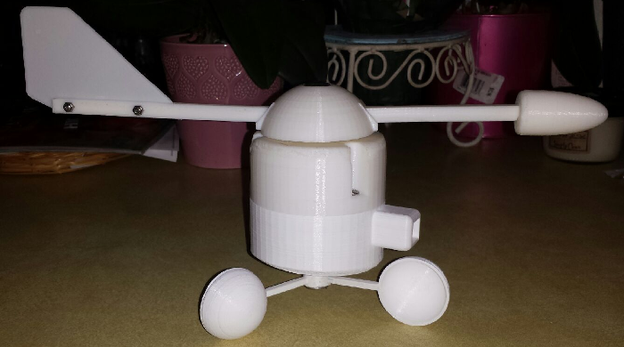
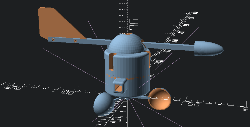
    for now it is still work in progress, here is little teaser of overall look
    0_1495694816412_IMG_20170519_171638.jpg


  • @Luc3as Thanks for the contribution. I have been quite busy the past few weeks and haven't had a lot of time to work more on the wind direction sensor. There are still a few issues I am working through with that before I can start jumping into the code for it. I am hoping to get more done this weekend.

    As for your 3D files, do you have them on thingiverse or somewhere accessible for us to check them out? I am interested in the work you have done.


  • Mod

    Those are quite a lot of solar panels. Is it that power hungry?


  • @gohan I can't see those small panels delivering that much. Plus, at certain parts of the day a number of the panels will most likely be shaded lowering their output.


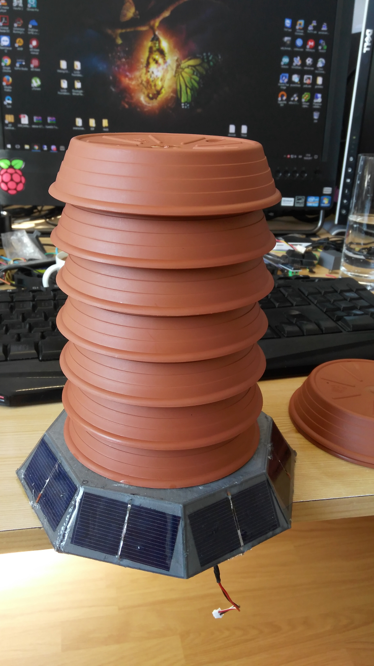
  • @dbemowsk yup, actually there are 8 of them, each providing nominal 0,5 volts, so to power up the lipo charger for battery I need at least 4 volts, in direct sunlight I think this will not be problem, but as @dbemowsk says, it will not have ideal position to sun every day and for whole time. but there is big enough reserve at battery , providing power for few days to weeks even without solar panel.
    and I am also checking voltage on solar panel so if there would be some problem with charging I can set notifications or something from home automation system.


  • I did some wind speed and direction sensor boards that I use in my own weather station design. All solid state and high resolution with analog signal readout, voltage for direction, 8 pulse per rev for speed. For inspiration see http://wws.us.to. Gary


  • Mod

    @Luc3as if you put solar panels in series you will get resistance from the shaded ones (at least that is what I saw in some experiments) . It would be better to have a single one pointing south that gathers the most sunlight and that's it


  • @gohan said in MySensors weather station:

    @Luc3as if you put solar panels in series you will get resistance from the shaded ones

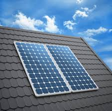
    That is correct, as far as what I have learned. Large monocrystaline and polycrystaline solar panels like the ones shown below have low to no output for the entire panel when one or more of the cells on a panel is shaded or covered.
    0_1495767863204_upload-5b7ebb13-0e24-46c9-9309-63bcf0032e7a

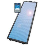
    Amorphous solar panels like these have closer to full output with less drop-off in shaded areas, but have a lower overall amperage output than monocrystaline and polycrystaline panels.
    0_1495768140607_upload-6ac6d03c-ceb7-4228-ac66-8918a44a6ea5

    The cells that @Luc3as has in his pic appear to be monocrystaline cells. Each cell will produce about 0.5 volts, so depending on the batteries you are using and the charging circuit, you could put some of these in series to create a couple banks, and then put the banks in parallel, you may get some usable power to charge a battery.


  • @GaryStofer I was checking out your weather station design. Nice work. Out of curiosity, what did you use for your wind direction sensor?


  • @dbemowsk Initially I uses an AS5030 encoder, but then I switched to the EM-3242 as it's much cheaper and smaller and does the same. My board has an Op-amp inverter to change the sense of angle to voltage so that the magnet can run on the top of the chip rather than on the bottom. Only problem we had with the EM-3242 was that it has no hysteresis which shows up at the 360/0 junction.


  • So, I had put this project on hold for a bit, but I am back at it. One of the parts of the project that I will be talking about in this post is the rain gauge portion of this. I had started a thread on this part a while back, but decided that I would combine everything for the weather station in this thread.

    So one of the things with this rain gauge was that I wanted to make it fairly accurate. In my "tipping bucket rain gauge" thread, @BulldogLowell had mentioned that an 8 inch opening on the funnel is typical for what is used commercially, so I went with that and designed this:
    0_1497912167330_upload-e18b1b01-0515-4e52-8869-e9ec3f454828
    0_1497912228058_upload-93bcefc3-6e26-4066-897f-6f7e668ec752
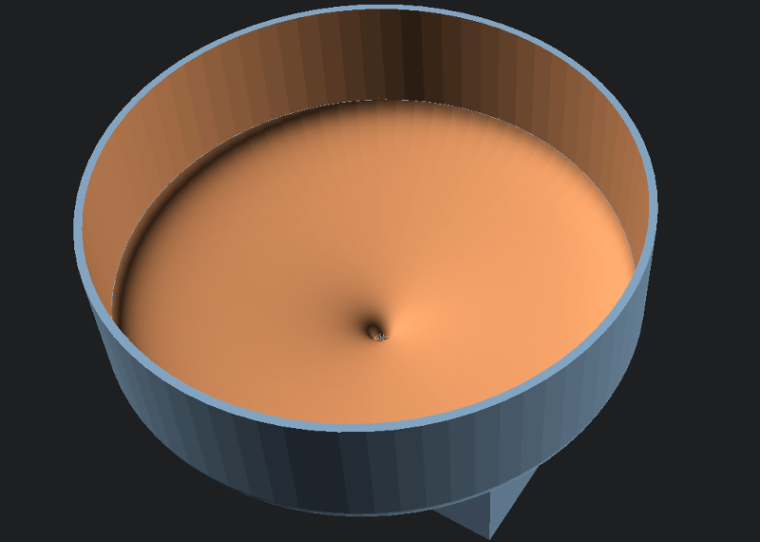
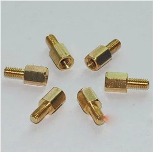
    Before I could print this on the 3D printer, I needed to print some different parts for my printer to allow for it to print the large size of the funnel. I also did some research on what type of plastic I should use before printing this monstrous part. Something I should have looked into more before printing the wind direction vane and wind speed rotor. Being that this will be outdoors in the sun it will need to have some UV resistance. I ended up settling on e-sun PETG filament. According to this review that I read, there was this statement that sold me on it:

    "It can also maintain the finished product's toughness and prevent it from turning into a yellowish color. PETG also contains UV absorber and can serve as a protective layer from the influence of ultraviolet light."

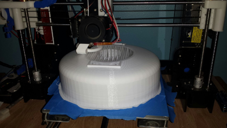
    At any rate, I just got my brand new roll of white and started the print:
    0_1497913538802_upload-f3954b84-720b-42d5-bfa9-6674b7d6e7c1
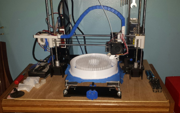
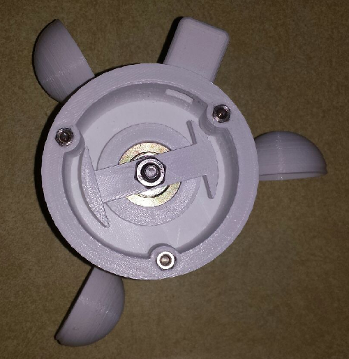
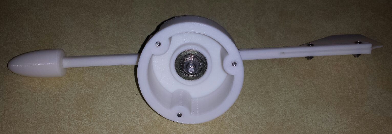
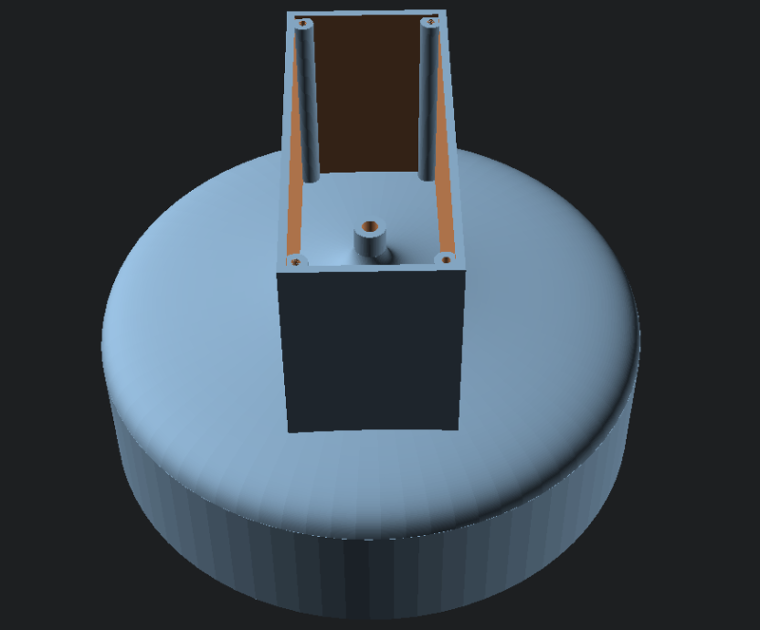
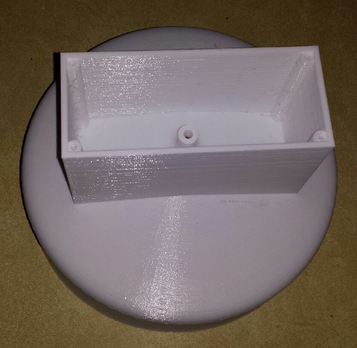
    I am running at a 0.24 layer height which should be fine for this. I am printing at 30 mm/s. Cura says 44 hours 40 minutes for the print, but the times from cura are usually a bit short. I am betting on about 48 hours total print time. This will be the largest print job I have ever had the printer do. The picture is at about 17 to 18 hours into the print.

    Tonight I will be tweaking the design of the base that will hold the tipping bucket and sensor. I did some test prints a while back of the basic parts of this to see how they would function, and I think they worked well. This is the basic design that I have as of now:
    0_1497915054416_upload-ac77942b-edef-44c7-b719-1c3f83dc2fca
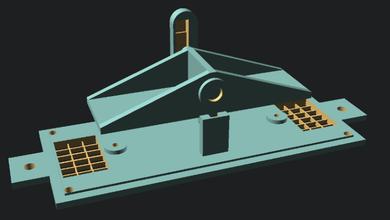
    A few tweaks to this and it should be good. The main thing is going to be figuring out how I want this to mount/attach to the rest of the system with the wind sensors and the arduino. Since this will just have the reed sensor, I will need to account for how it will get wired to the arduino. I am open for any suggestions on how to attach this to the rest of the sensors. My plan was to have some PVC pipes as the supports and mount things to that. I will need to watch out for the drain holes when mounting.

    All in all I think the project is coming along despite having to put it on hold for a while. As always, I am open to any feedback or suggestions that anyone can give.

    Thanks for reading.


  • thanks for this
    one of my cups on my anemometer is broken might be able to tweak that file instead of starting from scratch now


  • @MasterCATZ the anemometer that I used was one that I found on thingiverse. The link is in the beginning of the thread, but I am sure you found that already. You may want to just create a whole new cup rotor for yours.


  • Mod

    @dbemowsk that's quite a lot of support material ☺


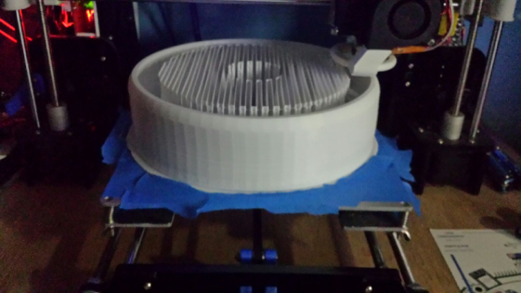
  • @gohan I agree, but I wanted to play it safe for when it got to the main funnel part. I opted to set the structure type to lines instead of a grid to at least keep the waste down some.

    Just over 24 hours into the print. As you can see in this updated pic, it is just starting to get to what will be the top part of the funnel where it is tapering in.
    0_1497937820531_upload-83c04d37-8a81-45b2-9365-97b38eb56b4a


  • Just an update on the progress. It just started on the box this morning. Should be finished tonight at some point.
    0_1497958856921_upload-537b0254-6498-4d49-86a9-5c88d9f525b6


  • Hello,

    I found this in the forum. Perhaps it helps for the wind direction detection.

    https://forum.mysensors.org/post/17825

    Especially here
    http://www.philpot.me/weatherinsider.html


  • @marco4711 Thanks for the links. I still have a few more things that I want to try to get my setup working If it comes down to it, I may use MasterCATZ' idea of using a magnetic rotational sensor. I don't give up easily.


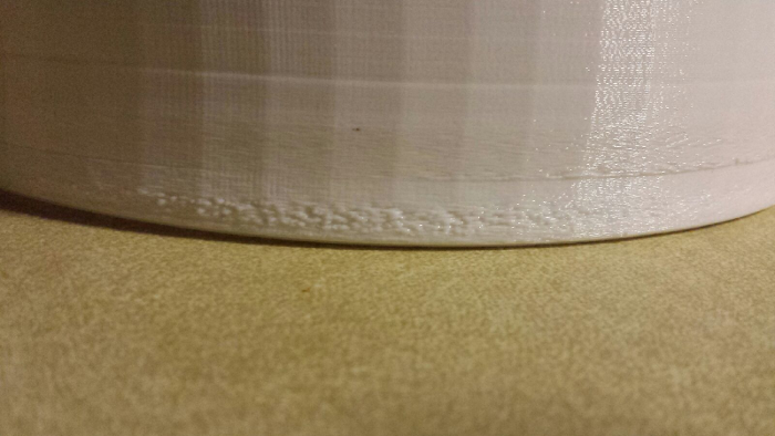
  • Well, the part finally finished. Roughly 46 hours. Overall, I think it will work good. It was a bit of a job clearing out all of the support material though.
    0_1498016481853_upload-8d7bd6b4-81c8-47d1-b5ea-634de160c85f

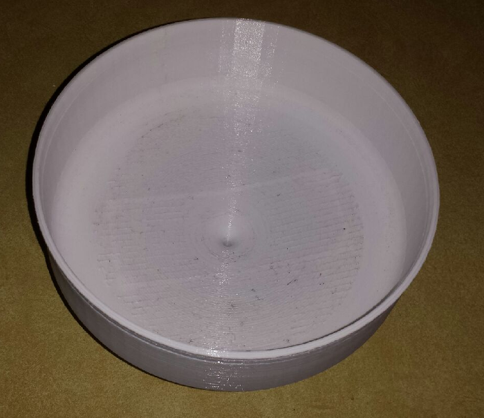
    The bottom turned out well.
    0_1498016713961_upload-c8b84df7-4dee-468d-baeb-ac2c8d91188b

    The first few layers had some issues, but really nothing that will defeat it's purpose. Had me worried for a short time though, but I gave it the benefit of the doubt.
    0_1498016851444_upload-f03e5ee9-a10f-498c-93dd-0d5985544c58


  • So, for the latest addition to my weather station, I decided to make a radiation shield to house a DHT22 temp and humidity sensor. I figured that I would also need a place to put the arduino to be used as a connection hub for everything and I figured this would be as good a place as any. This is my design for it:
    0_1498978951186_upload-fc2eb2a2-f4be-4e60-b58f-d8acacfde543

    The under side of the base is where the electronics will be mounted. I have designed the standoffs to mount an easy newbie board. and should have plenty of room for wire connections as these will be fairly basic.
    0_1498979383692_upload-f73c8994-4742-42f0-b710-6d097e4e3fbc

    In the event that water should get inside of the unit due to wind or other factors, I have designed the bottom cover with a tapered center going to a drain hole.
    0_1498979569506_upload-bba6491f-732a-4a60-bc61-897dc90f2f70

    I have the radiation shield and rain gauge partially assembled for now for programming and testing. I will get some better pictures of that tomorrow and post them to the thread.

    One other change that I decided on was for the wind direction sensor. Since I had a bit of trouble with the other designs that I tested using reed switches and IR phototransistors, I decided to try an AS5047P magnetic direction sensor. I ordered this one off of ebay. It was a bit expensive at $16 US plus $3.39 for shipping, but the person selling it mentioned that it comes with an extra chip. These sell on Digikey for $17 plus $7 and change for shipping, and the chips alone sell for around $9, so I didn't think it was that bad of a deal. I should have that later this week.
    0_1498980091138_upload-31626253-dcaf-4ca5-b68e-f4d11c479f05

    Once I get this assembled I think the last thing will be to figure out all of the programming, which I have a bit of a start on using the rain gauge code from the build section of the site. I have been researching the code for the anemometer, and that may take a bit of planning with everything else that I have running, but I think it can be done. With the new direction sensor module, that should be pretty straight forward as far as connection and code, I just need to decide if I want to connect it with SPI or straight analog. I am thinking though that this project is nearing completion. It was a bit of a learning curve building all of the parts, but I think it was a good journey.

    As mentioned, I'll post more pics tomorrow.


  • looking good

    I need to beef up my solar panels

    I get 1 week before the low battery indicator switches on and I loose half my distance

    instead of using 2x AA 1.5v batteries ( or 1.2v rechargeables )

    I am just going to run 18650 cells and use a 4v solar panel


  • @MasterCATZ I had actually thought of getting a small 6 volt SLA or AGM battery and connecting a small solar panel to it. I can knock out an easy battery box with a solar panel mount on my 3D printer. These are the solar panels I was looking at as possibilities:
    https://www.amazon.com/Sunnytech-333ma-Module-System-Charger/dp/B00HQXQOIQ/ref=sr_1_28?ie=UTF8&qid=1499001654&sr=8-28&keywords=6+volt+solar+panel+charger
    https://www.amazon.com/Portable-Module-System-Battery-Charger/dp/B01JLPM81I/ref=sr_1_39?ie=UTF8&qid=1499001192&sr=8-39&keywords=6+volt+solar+panel+charger
    I just need enough power from the panel to power the arduino and sensors during the day plus a little extra to top off the battery. I figured if I ever decide to add more sensors to the station I'll have all the power I need to handle whatever I put on it. I have my Easy Newbie board set up with a 5V pro mini and power coming into the RAW input. I think I'll be set.


  • Here are a couple pics of my first prototype mounting layout of the sensors. I may still use some elbows and get the anemometer and wind direction vane moved a bit higher than the other sensors. My fear is that with all of the sensors sitting on the same plane, wind passing by the other sensor housings may affect the readings of these. The main one I am concerned with is the rain sensor. This is a minor obstacle that can be fixed with two PVC elbows.
    0_1499028515008_upload-d23be907-c68e-4994-863c-4f73824bb0ba0_1499028531031_upload-1b3c57ac-913d-4ddd-aa07-2552f9f2e78e

    Another thing, I was thinking about the batteries that I want to use with this and I noticed that I have had the 4 - AA battery pack on for a few days now and they are still running. If I put together a pack of 2 18650 batteries, I should be good. Those batteries run at 3.7 volts, so 2 of them should give my 7.4 volts which should be no problem on the RAW input of the pro mini. My only worry with these would be overcharging them. Being that these are lithium ion batteries, they can be dangerous if overcharged. Just need to find a decent solar charging circuit for them. I am open for suggestions if anyone has any.

    I hope within the next week I can have all of the OpenSCAD files cleaned up and posted on thingiverse. I wanted to post some of them a while back, but ended up making a few minor tweaks.

    Enjoy...


  • So today as I was working on the rig to change the placement of the anemometer/wind direction assembly, I ended up dropping the assembly and broke one of the cups off. As I was getting ready to make a new wind cup assembly, I decided to make a small change in the design. The change that I made has the arms holding the cups lower to better prevent wind interference from the housing. Here is the new design.
    0_1499058501983_upload-14e57d76-754e-42f9-93c1-2674252c6a5b

    I will post more pics tomorrow of the change in placement of the anemometer assembly with the new cups.


  • Mod

    You could power the pro mini directly to vcc using just one lithium cell and remove the voltage regulator and led to save power.


  • @gohan Right now the only Pro Minis that I have left in my parts bin are 5 volt ones. Besides, I already have the newbie board fitted with the 3.3v regulator and power caps. Another compelling reason for using a 5v mini is that it is 16MHz instead of 8MHz for the 3.3v ones. I think that I am going to want the extra speed for the number of sensors I have connected to a single pro mini and the data that I need to collect. I need to use interrupts for the pulse counting of the anemometer, so the faster I can do those things, the better off I'll be.


  • Hardware Contributor

    @dbemowsk - are your goal to sleep this sensor or whats your thoughts running it with battery? It might be a hard nut to crack 5v 16mhz and batteries?

    Love your thread btw! Keep up the good work 🙂


  • @sundberg84 I don't plan to sleep the sensor at all. Putting the sensor to sleep would cause problems with the anemometer and the interrupt I need to use for that. The main reason for needing it to run on battery is that I plan to mount this up in the air on the top edge of my house. This is why I want to also put a solar panel on it. During the day the solar panel can run the sensor and charge the battery, and at night the battery can take over.


  • Mod

    Are you sure you don't want to sleep sensor? If it is a matter of interrupts for anemometer, you could use a dinamic sleep time, like if you don't have any wind motion within 2 seconds put the node to sleep and wake it up on pin change


  • @gohan I have never worked with a dynamic sleep timer. Do you have am example of how this is used?


  • Mod

    Not really, maybe just put the sleep in an IF statement and check if the time from last impulse from the anemometer is over than 2 sec then sleep, otherwise it just continues loop


  • @gohan So am I correct in assuming that an interrupt will wake a sleep timer? As long as I can catch the pulses from the anemometer, I don't see a reason I couldn't use a sleep timer. Just thinking about it, I may also want to use an interrupt for the rain gauge sensor for similar reasons. Not sure about the wind direction sensor.


  • Here are a few more pictures of the new layout with the new anemometer cups.
    0_1499087266284_upload-2b958d54-e3bb-4ae1-9ba4-815bc9ac5f88
    0_1499087278053_upload-dec6c2b6-ee03-4891-9f89-161246ed722f
    0_1499087288381_upload-164b9af0-fe6c-4ebf-ab25-e675e10c41d7


  • Mod

    @dbemowsk basically you would need to attach sleep to both interrupts on pin 2 and 3 and use them for anemometer and rain meter. For wind direction check it when it wakes up


  • So I am trying to figure out code for the wind speed sensor and I see there is a V_GUST value. I am wondering what people use for that value.


  • So now that I have the wind direction sensor working, I need to try to migrate the code into my weather_station sketch. One option that I am working on implementing is a calibration button for North. So after I get things set up and mounted, I will use a compass to point the wind vane towards North. I will then press the calibration button which will save the current direction position to EEPROM if it is different than the one stored. The following code will then be used to get the true direction that the wind vane is pointing.

    value = 360 * myAS5047.sensor_read() / 16383; //Read the value from the direction sensor as a value from 0 to 360
    north_offset = EEPROM.read(address);  //Read the offset value from EEPROM
    
    dir = ((value - north_offset) < 0) ? 360 - abs (value - north_offset)  : value - north_offset; //Get the true direction
    /*
    insert code to read the button and if pressed, check the current value stored in EEPROM against the value read from the sensor
    and write the new value if it is different.  If the sensor value matches the current stored value, then ignore the write to
    save on EEPROM writes.
    */
    

    So with this idea, I will need to know a few things. First, I am assuming that MySensors does EEPROM writes and reads. Is there a particular addreess pointer variable that I should use when writing my value to EEPROM? I will also need to know how I can get the address pointer to that data the same each time the arduino is reset, especially if MySensors does writes and reads.

    As always, any input is appreciated.


  • Hardware Contributor

    Hello, @dbemowsk
    You should use the built in method from the MySensors library to do that :
    https://www.mysensors.org/download/sensor_api_20#saving-state


  • @Nca78 Thanks, exactly what I wanted to know.


  • @Nca78 So my values are from 0 to 360, looking at the link you posted, the value that you save to an address is uint8_t which is equivalent to a byte (0 to 255). Is there a way to store a word value (uint16_t), or do I need to break the value into two bytes and store those into two positions?


  • Hardware Contributor

    @dbemowsk said in MySensors weather station:

    @Nca78 So my values are from 0 to 360, looking at the link you posted, the value that you save to an address is uint8_t which is equivalent to a byte (0 to 255). Is there a way to store a word value (uint16_t), or do I need to break the value into two bytes and store those into two positions?

    Yes it can only store bytes, but it's not a big deal to make a method to read/write values on 2 bytes.
    Else you can just keep a precision of 2° and divide by 2 to get a 0=>180 value 😉


  • Actually thinking about this, I should be using 0 to 359. 0 to 360 is actually 361 positions, not 360.


  • Mod

    Precision of 2° I believe it's enough as many weather stations provide just the 8 general directions


  • @gohan It would only be for saving the offset for north, so I think I will do that.


  • So I am trying to figure out the SPI for the wind direction sensor. Where is the SPI code for MySensors. Do I need to call SPI.begin()? Does MySensors code use transactions? If so, where can I find that to look at.


  • Mod

    Doesn't it have a library?


  • @gohan It does, but it is an untested library. This is the test code that I ran using that library:

    #include "AS5047.h"
    #include <SPI.h>
    #include <EEPROM.h>
    
    #define SWITCH_PIN 7 //The north calibration switch
    
    AS5047 myAS5047(5); // SS pin
     
    int address = 0;      //EEPROM address counter
    int north_offset = 0;
    long value;
    int dir;
    bool button;
    
    void setup()
    {
      SPI.begin;
      Serial.begin(9600);
    
      pinMode(SWITCH_PIN, INPUT_PULLUP);
    
      north_offset = EEPROM.read(address);
    }
    
    void loop()
    {
      value=(360*myAS5047.sensor_read())/16383;
      dir = ((value - north_offset) < 0) ? 360 - abs(value - north_offset) : value - north_offset;
      
      Serial.print("measured direction: ");
      Serial.println(dir);
      Serial.print("north_offset: ");
      Serial.println(north_offset);
    
      button = digitalRead(SWITCH_PIN);
      north_offset = EEPROM.read(address);
      if (!button && north_offset != value) {
        EEPROM.write(address, value);
        north_offset = value;
        Serial.println("Button pressed");
      }
      
      delay(1000);
    }
    

    This test worked fine, now I am trying to merge this with my weather station sketch. I am not very familiar with working with SPI. In the setup() method, they call SPI.begin(). I am just trying to figure out what I need to do for merging the code.


  • Should all of the SPI stuff be included in the library?


  • So now I have the direction sensor on the SPI bus with the CS pin connected to D5 on my easy newbie board. If I run my sample program for the direction sensor to test it on the bus with the nRF24 radio, I get readings and it seems to work fine. The problem is, if I run my modified rain sensor sketch seen below, I cannot get the radio to work.

    /*
     Arduino Tipping Bucket Rain Gauge
    
     April 26, 2015
    
     Version 2.0
    
     Arduino Tipping Bucket Rain Gauge
    
     Utilizing a tipping bucket sensor, your Vera home automation controller and the MySensors.org
     gateway you can measure and sense local rain.  This sketch will create two devices on your
     Vera controller.  One will display your total precipitation for the last 5 days.  The other, 
     a sensor that changes state if there is recent rain (up to last 120 hours)  above a threshold.  
     Both these settings are user definable.
    
     There is a build overview video here: https://youtu.be/1eMfKQaLROo
    
     This sketch features the following:
    
     * Allows you to set the rain threshold in mm
     * Allows you to determine the tripped indicator window up to 120 hours.
     * Displays the last 5 days of rain in Variable1 through Variable5
       of the Rain Sensor device
     * Configuration changes to Sensor device updated every hour
     * Should run on any Arduino
     * Will retain Tripped/Not Tripped status and data in a power interruption, saving small amount
       of data to EEPROM (Circular Buffer to maximize life of EEPROM)
     * LED status indicator
     * Optional Temp/Humidity (DHT-22 or DHT-11) and Light LUX (BH1750) sensors. To use, uncomment
       #define DHT_ON  and/or #define LUX_ON
     * Optionally send total accumulation of each day's rainfall or send only individual days rainfall totals.
       Uncomment #define USE_DAILY to display individual daily rainfall.  If it is commented out it will display
       a cumulative total rainfall (day4 = day1+day2+day3+day4 etc)
    
     by @BulldogLowell and @PeteWill for free public use
    
     */
    
    #define MY_DEBUG // Enable MySensors debug prints to serial monitor
    
    // Enable and select radio type attached
    #define MY_RADIO_NRF24
    //#define MY_RADIO_RFM69
    
    //#define MY_NODE_ID 7 //uncomment this line to assign a static ID
    
    #include <SPI.h>
    #include <math.h>
    #include <TimeLib.h>
    #include "AS5047.h"
    #include <MySensors.h>
    
    #define SKETCH_NAME "Weather Station"
    #define SKETCH_VERSION "2.0"
    
    #define DWELL_TIME 40  // this allows for radio to come back to power after a transmission, ideally 0 
    
    //#define DEBUG_ON  // Rain gauge specific debug messages. 
    #define DHT_ON // uncomment out this line to enable DHT sensor
    //#define LUX_ON // uncomment out this line to enable BH1750 sensor
    //#define USE_DAILY // Uncomment to display individual daily rainfall totals in the variables sent to your controller. If it's commented it will add each day to the next for a cumulative total.
    
    #define NORTH_SWITCH_PIN 7 //The north calibration switch
    #define AS5047_CHIP_SELECT_PIN 5 //The north calibration switch
    
    #define TIP_SENSOR_PIN 2 //The tipping bucket rain sensor
    #define CALIBRATE_FACTOR 60 // amount of rain per rain bucket tip e.g. 5 is .05mm
    #define DHT_LUX_DELAY 300000  //Delay in milliseconds that the DHT and LUX sensors will wait before sending data
    #define WIND_DIR_DELAY 300000  //Delay in milliseconds that the DHT and LUX sensors will wait before sending data
    
    #define CHILD_ID_RAIN_LOG 3  // Keeps track of accumulated rainfall
    #define CHILD_ID_TRIPPED_INDICATOR 4  // Indicates Tripped when rain detected
    #define CHILD_ID_WIND 5  // Indicates Tripped when rain detected
    
    #define EEPROM_NORTH_OFFSET_LOCATION 0  // location of the EEPROM circular buffer
    #define EEPROM_BUFFER_LOCATION 1  // location of the EEPROM circular buffer
    #define E_BUFFER_LENGTH 240
    #define RAIN_BUCKET_SIZE 120
    
    #ifdef  DEBUG_ON
      #define DEBUG_PRINT(x)   Serial.print(x)
      #define DEBUG_PRINTLN(x) Serial.println(x)
      #define SERIAL_START(x)  Serial.begin(x)
      #else
      #define DEBUG_PRINT(x)
      #define DEBUG_PRINTLN(x)
      #define SERIAL_START(x)
    #endif
    //
    MyMessage msgRainRate(CHILD_ID_RAIN_LOG, V_RAINRATE);
    MyMessage msgRain(CHILD_ID_RAIN_LOG, V_RAIN);
    //
    MyMessage msgRainVAR1(CHILD_ID_RAIN_LOG, V_VAR1);
    MyMessage msgRainVAR2(CHILD_ID_RAIN_LOG, V_VAR2);
    MyMessage msgRainVAR3(CHILD_ID_RAIN_LOG, V_VAR3);
    MyMessage msgRainVAR4(CHILD_ID_RAIN_LOG, V_VAR4);
    MyMessage msgRainVAR5(CHILD_ID_RAIN_LOG, V_VAR5);
    //
    MyMessage msgTripped(CHILD_ID_TRIPPED_INDICATOR, V_TRIPPED);
    MyMessage msgTrippedVar1(CHILD_ID_TRIPPED_INDICATOR, V_VAR1);
    MyMessage msgTrippedVar2(CHILD_ID_TRIPPED_INDICATOR, V_VAR2);
    
    MyMessage msgWindSpeed(CHILD_ID_WIND, V_WIND);
    MyMessage msgWindGust(CHILD_ID_WIND, V_GUST);
    MyMessage msgWindDirection(CHILD_ID_WIND, V_DIRECTION);
    //
    #ifdef DHT_ON
      #include <DHT.h>
      #define CHILD_ID_HUM 0
      #define CHILD_ID_TEMP 1
      #define HUMIDITY_SENSOR_DIGITAL_PIN 3
      DHT dht;
      float lastTemp;
      float lastHum;
      bool metric = false;
      MyMessage msgHum(CHILD_ID_HUM, V_HUM);
      MyMessage msgTemp(CHILD_ID_TEMP, V_TEMP);
    #endif
    //
    #ifdef LUX_ON
      //BH1750 is connected to SCL (analog input A5) and SDA (analog input A4)
      #include <BH1750.h>
      #include <Wire.h>
      #define CHILD_ID_LIGHT 2
      BH1750 lightSensor;
      MyMessage msg(CHILD_ID_LIGHT, V_LIGHT_LEVEL);
      unsigned int lastlux;
      uint8_t heartbeat = 10; //Used to send the light lux to gateway as soon as the device is restarted and after the DHT_LUX_DELAY has happened 10 times
    #endif
    
    AS5047 myAS5047(5); //AS5047_CHIP_SELECT_PIN); //Wind direction magnetic position sensor
    uint8_t north_offset;
    bool button;
    int wind_direction;
    int last_direction;
    
    unsigned long sensorPreviousMillis;
    unsigned long windDirPreviousMillis;
    int eepromIndex;
    int tipSensorPin = 3; // Pin the tipping bucket is connected to. Must be interrupt capable pin
    int ledPin = 5; // Pin the LED is connected to.  PWM capable pin required
    #ifdef DEBUG_ON
    unsigned long dataMillis;
    unsigned long serialInterval = 600000UL;
    #endif
    const unsigned long oneHour = 3600000UL;
    unsigned long lastTipTime;
    unsigned long lastRainTime; //Used for rainRate calculation
    unsigned int rainBucket [RAIN_BUCKET_SIZE] ; /* 24 hours x 5 Days = 120 hours */
    unsigned int rainRate = 0;
    uint8_t rainWindow = 72;         //default rain window in hours.  Will be overwritten with msgTrippedVar1.
    volatile int wasTippedBuffer = 0;
    int rainSensorThreshold = 50; //default rain sensor sensitivity in hundredths.  Will be overwritten with msgTrippedVar2.
    uint8_t state = 0;
    uint8_t oldState = 2; //Setting the default to something other than 1 or 0
    unsigned int lastRainRate = 0;
    int lastMeasure = 0;
    bool gotTime = false;
    uint8_t lastHour;
    uint8_t currentHour;
    //
    void presentation()  {
      // Register all sensors to gw (they will be created as child devices)
      sendSketchInfo(SKETCH_NAME, SKETCH_VERSION);
      wait(DWELL_TIME);
      present(CHILD_ID_RAIN_LOG, S_RAIN);
      wait(DWELL_TIME);
      present(CHILD_ID_TRIPPED_INDICATOR, S_MOTION);
      wait(DWELL_TIME);
    
      present(CHILD_ID_WIND, S_WIND);
      wait(DWELL_TIME);
    
    #ifdef DHT_ON
      present(CHILD_ID_HUM, S_HUM);
      wait(DWELL_TIME);
      present(CHILD_ID_TEMP, S_TEMP);
      wait(DWELL_TIME);
    #endif
    
    
    #ifdef LUX_ON
      present(CHILD_ID_LIGHT, S_LIGHT_LEVEL);
    #endif
    
      DEBUG_PRINTLN(F("Sensor Presentation Complete"));
    }
    
    void setup()
    {
      #ifndef MY_DEBUG
      SERIAL_START(115200);  //Start serial if MySensors debugging isn't enabled
      #endif
      //
      pinMode(NORTH_SWITCH_PIN, INPUT_PULLUP);
      
      // Set up the IO
      pinMode(TIP_SENSOR_PIN, INPUT_PULLUP);
      attachInterrupt (digitalPinToInterrupt(TIP_SENSOR_PIN), sensorTipped, FALLING);  // depending on location of the hall effect sensor may need CHANGE
      pinMode(ledPin, OUTPUT);
      digitalWrite(ledPin, HIGH);
      //
      //Sync time with the server
      //
      unsigned long functionTimeout = millis();
      while (timeStatus() == timeNotSet && millis() - functionTimeout < 30000UL)
      {
        requestTime();
        DEBUG_PRINTLN(F("Getting Time"));
        wait(1000); // call once per second
        DEBUG_PRINTLN(F("."));
      }
      currentHour = hour();
      lastHour = hour();
      //
      //retrieve from EEPROM stored values on a power cycle.
      //
      
      //Get the north offset direction
      north_offset = loadState(EEPROM_NORTH_OFFSET_LOCATION)*2;
      
      bool isDataOnEeprom = false;
      for (int i = 0; i < E_BUFFER_LENGTH; i++)
      {
        uint8_t locator = loadState(EEPROM_BUFFER_LOCATION + i);
        if (locator == 0xFE)  // found the EEPROM circular buffer index
        {
          eepromIndex = EEPROM_BUFFER_LOCATION + i;
          DEBUG_PRINT(F("EEPROM Index "));
          DEBUG_PRINTLN(eepromIndex);
          //Now that we have the buffer index let's populate the rainBucket[] with data from eeprom
          loadRainArray(eepromIndex);
          isDataOnEeprom = true;
          break;
        }
      }
      //
      if (!isDataOnEeprom) // Added for the first time it is run on a new Arduino
      {
        DEBUG_PRINTLN(F("I didn't find valid EEPROM Index, so I'm writing one to location 0"));
        eepromIndex = EEPROM_BUFFER_LOCATION;
        saveState(eepromIndex, 0xFE);
        saveState(eepromIndex + 1, 0xFE);
        //then I will clear out any bad data
        for (int i = 2; i <= E_BUFFER_LENGTH; i++)
        {
          saveState(i, 0x00);
        }
      }
      #ifdef DEBUG_ON
      dataMillis = millis();
      #endif
      lastTipTime = millis(); 
      //
      request(CHILD_ID_TRIPPED_INDICATOR, V_VAR1);
      wait(DWELL_TIME);
      request(CHILD_ID_TRIPPED_INDICATOR, V_VAR2);
      wait(DWELL_TIME);
      //
    #ifdef DHT_ON
      dht.setup(HUMIDITY_SENSOR_DIGITAL_PIN);
      metric = getConfig().isMetric;
      //metric = false;
      wait(DWELL_TIME);
    #endif
      //
    #ifdef LUX_ON
      lightSensor.begin();
    #endif
      //
      transmitRainData(); //Setup complete send any data loaded from eeprom to gateway
    }
    
    void loop()
    {
      if (state)
      {
        prettyFade();  // breathe if tripped
      }
      else
      {
        slowFlash();   // blink if not tripped
      }
    #ifdef DEBUG_ON  // Serial Debug Block
      if ( (millis() - dataMillis) >= serialInterval)
      {
        for (int i = 24; i <= 120; i = i + 24)
        {
          updateSerialData(i);
        }
        dataMillis = millis();
      }
    #endif
    
      //NORTH_SWITCH_PIN
      button = digitalRead(NORTH_SWITCH_PIN);
      if (!button) {
        setNorthOffset();
      } 
      
      //
      // let's constantly check to see if the rain in the past rainWindow hours is greater than rainSensorThreshold
      //
      int measure = 0; // Check to see if we need to show sensor tripped in this block
      for (int i = 0; i < rainWindow; i++)
      {
        measure += rainBucket [i];
        if (measure != lastMeasure)
        {
          //      DEBUG_PRINT(F("measure value (total rainBucket within rainWindow): "));
          //      DEBUG_PRINTLN(measure);
          lastMeasure = measure;
        }
      }
      //
      state = (measure >= (rainSensorThreshold * 100));
      if (state != oldState)
      {
        send(msgTripped.set(state));
        wait(DWELL_TIME);
        DEBUG_PRINT(F("New Sensor State... Sensor: "));
        DEBUG_PRINTLN(state ? "Tripped" : "Not Tripped");
        oldState = state;
      }
      //WIND_DIR_DELAY
      if (millis() - windDirPreviousMillis > WIND_DIR_DELAY)
      {
        wind_direction = getWindDirection();
        if (wind_direction != last_direction)
        {
          send(msgWindDirection.set(wind_direction));
        }
        last_direction = wind_direction;
        windDirPreviousMillis = millis();
      }
      //
      unsigned long tipDelay = millis() - lastRainTime;
      if (wasTippedBuffer) // if was tipped, then update the 24hour total and transmit to Vera
      {
        DEBUG_PRINTLN(F("Sensor Tipped"));
        DEBUG_PRINT(F("rainBucket [0] value: "));
        DEBUG_PRINTLN(rainBucket [0]);
        send(msgRain.set((float)rainTotal(currentHour) / 100, 1)); //Calculate the total rain for the day
        wait(DWELL_TIME);
        wasTippedBuffer--;
        rainRate = ((oneHour) / tipDelay);
        if (rainRate != lastRainRate)
        {
          send(msgRainRate.set(rainRate, 1));
          wait(DWELL_TIME);
          DEBUG_PRINT(F("RainRate= "));
          DEBUG_PRINTLN(rainRate);
          lastRainRate = rainRate;
        }
        lastRainTime = lastTipTime;
      }
      //
      currentHour = hour();
      if (currentHour != lastHour)
      {
        DEBUG_PRINTLN(F("One hour elapsed."));
        send(msgRain.set((float)rainTotal(currentHour) / 100, 1)); // send today's rainfall
        wait(DWELL_TIME);
        saveState(eepromIndex, highByte(rainBucket[0]));
        saveState(eepromIndex + 1, lowByte(rainBucket[0]));
        DEBUG_PRINT(F("Saving rainBucket[0] to eeprom. rainBucket[0] = "));
        DEBUG_PRINTLN(rainBucket[0]);
        for (int i = RAIN_BUCKET_SIZE - 1; i >= 0; i--)//cascade an hour of values back into the array
        {
          rainBucket [i + 1] = rainBucket [i];
        }
        request(CHILD_ID_TRIPPED_INDICATOR, V_VAR1);
        wait(DWELL_TIME);
        request(CHILD_ID_TRIPPED_INDICATOR, V_VAR2);
        wait(DWELL_TIME);
        rainBucket[0] = 0;
        eepromIndex = eepromIndex + 2;
        if (eepromIndex > EEPROM_BUFFER_LOCATION + E_BUFFER_LENGTH)
        {
          eepromIndex = EEPROM_BUFFER_LOCATION;
        }
        DEBUG_PRINT(F("Writing to EEPROM.  Index: "));
        DEBUG_PRINTLN(eepromIndex);
        saveState(eepromIndex, 0xFE);
        saveState(eepromIndex + 1, 0xFE);
        requestTime(); // sync the time every hour
        wait(DWELL_TIME);
        transmitRainData();
        rainRate = 0;
        send(msgRainRate.set(rainRate, 1));
        wait(DWELL_TIME);
        DEBUG_PRINTLN(F("Sending rainRate is 0 to controller"));
        lastHour = hour();
      }
      if (millis() - sensorPreviousMillis > DHT_LUX_DELAY)
      {
        #ifdef DHT_ON  //DHT Code
          doDHT();
        #endif
        #ifdef LUX_ON
          doLUX();
        #endif
        sensorPreviousMillis = millis();
      }
    }
    
    int getWindDirection() 
    {
      north_offset = loadState(EEPROM_NORTH_OFFSET_LOCATION);
      
      int value = readDir();
      int dir = ((value - north_offset) < 0) ? 360 - abs(value - north_offset) : value - north_offset;
        DEBUG_PRINT("Wind direction: ");
        DEBUG_PRINTLN(dir);
      return dir;
    }
    
    //
    void setNorthOffset() 
    {
      int value = readDir();
      if (north_offset != value)
      {
        saveState(EEPROM_NORTH_OFFSET_LOCATION, value/2);
        north_offset = value;
        DEBUG_PRINT("North offset set to: ");
        DEBUG_PRINTLN(value/2);
      }
    }
    int readDir() 
    {
      int value = (359*myAS5047.sensor_read())/16383;
      return value;
    }
    //
    #ifdef DHT_ON
    void doDHT(void)
    {
      float temperature = dht.getTemperature();
        if (isnan(temperature)) 
        {
          DEBUG_PRINTLN(F("Failed reading temperature from DHT"));
        } else if (temperature != lastTemp) 
        {
          lastTemp = temperature;
          if (!metric) 
          {
            temperature = dht.toFahrenheit(temperature);
          }
          send(msgTemp.set(temperature, 1));
          wait(DWELL_TIME);
          DEBUG_PRINT(F("Temperature is: "));
          DEBUG_PRINTLN(temperature);
        }
        float humidity = dht.getHumidity();;
        if (isnan(humidity)) 
        {
          DEBUG_PRINTLN(F("Failed reading humidity from DHT"));
        } else if (humidity != lastHum) 
        {
          lastHum = humidity;
          send(msgHum.set(humidity, 1));
          wait(DWELL_TIME);
          DEBUG_PRINT(F("Humidity is: "));
          DEBUG_PRINTLN(humidity);
        }
    }
    #endif
    //
    #ifdef LUX_ON
    void doLUX(void)
    {
      unsigned int lux = lightSensor.readLightLevel();// Get Lux value
      DEBUG_PRINT(F("Current LUX Level: "));
      DEBUG_PRINTLN(lux);
      heartbeat++;
      if (lux != lastlux || heartbeat > 10) 
      {
        send(msg.set(lux));
        lastlux = lux;
      }
      if (heartbeat > 10) 
      {
        heartbeat = 0;
      }
    }
    #endif
    //
    void sensorTipped()
    {
      unsigned long thisTipTime = millis();
      if (thisTipTime - lastTipTime > 100UL)
      {
        rainBucket[0] += CALIBRATE_FACTOR; // adds CALIBRATE_FACTOR hundredths of unit each tip
        wasTippedBuffer++;
      }
      lastTipTime = thisTipTime;
    }
    //
    int rainTotal(int hours)
    {
      int total = 0;
      for ( int i = 0; i <= hours; i++)
      {
        total += rainBucket [i];
      }
      return total;
    }
    
    #ifdef DEBUG_ON
    void updateSerialData(int x)
    {
      DEBUG_PRINT(F("Rain last "));
      DEBUG_PRINT(x);
      DEBUG_PRINTLN(F(" hours: "));
      float tipCount = 0;
      for (int i = 0; i < x; i++)
      {
        tipCount = tipCount + rainBucket [i];
      }
      tipCount = tipCount / 100;
      DEBUG_PRINTLN(tipCount);
    }
    #endif
    
    void loadRainArray(int eValue) // retrieve stored rain array from EEPROM on powerup
    {
      for (int i = 1; i < RAIN_BUCKET_SIZE; i++)
      {
        eValue = eValue - 2;
        if (eValue < EEPROM_BUFFER_LOCATION)
        {
          eValue = EEPROM_BUFFER_LOCATION + E_BUFFER_LENGTH;
        }
        DEBUG_PRINT(F("EEPROM location: "));
        DEBUG_PRINTLN(eValue);
        uint8_t rainValueHigh = loadState(eValue);
        uint8_t rainValueLow = loadState(eValue + 1);
        unsigned int rainValue = rainValueHigh << 8;
        rainValue |= rainValueLow;
        rainBucket[i] = rainValue;
        //
        DEBUG_PRINT(F("rainBucket[ value: "));
        DEBUG_PRINT(i);
        DEBUG_PRINT(F("] value: "));
        DEBUG_PRINTLN(rainBucket[i]);
      }
    }
    
    void transmitRainData(void)
    {
      DEBUG_PRINT(F("In transmitRainData. currentHour = "));
      DEBUG_PRINTLN(currentHour);
      int rainUpdateTotal = 0;
      for (int i = currentHour; i >= 0; i--)
      {
        rainUpdateTotal += rainBucket[i];
        DEBUG_PRINT(F("Adding rainBucket["));
        DEBUG_PRINT(i);
        DEBUG_PRINTLN(F("] to rainUpdateTotal."));
      }
      DEBUG_PRINT(F("TX Day 1: rainUpdateTotal = "));
      DEBUG_PRINTLN((float)rainUpdateTotal / 100.0);
      send(msgRainVAR1.set((float)rainUpdateTotal / 100.0, 1)); //Send current day rain totals (resets at midnight)
      wait(DWELL_TIME);
    #ifdef USE_DAILY
      rainUpdateTotal = 0;
    #endif
      for (int i = currentHour + 24; i > currentHour; i--)
      {
        rainUpdateTotal += rainBucket[i];
        DEBUG_PRINT(F("Adding rainBucket["));
        DEBUG_PRINT(i);
        DEBUG_PRINTLN(F("] to rainUpdateTotal."));
      }
      DEBUG_PRINT(F("TX Day 2: rainUpdateTotal = "));
      DEBUG_PRINTLN((float)rainUpdateTotal / 100.0);
      send(msgRainVAR2.set((float)rainUpdateTotal / 100.0, 1));
      wait(DWELL_TIME);
    #ifdef USE_DAILY
      rainUpdateTotal = 0;
    #endif
      for (int i = currentHour + 48; i > currentHour + 24; i--)
      {
        rainUpdateTotal += rainBucket[i];
        DEBUG_PRINT(F("Adding rainBucket["));
        DEBUG_PRINT(i);
        DEBUG_PRINTLN(F("] to rainUpdateTotal."));
      }
      DEBUG_PRINT(F("TX Day 3: rainUpdateTotal = "));
      DEBUG_PRINTLN((float)rainUpdateTotal / 100.0);
      send(msgRainVAR3.set((float)rainUpdateTotal / 100.0, 1));
      wait(DWELL_TIME);
    #ifdef USE_DAILY
      rainUpdateTotal = 0;
    #endif
      for (int i = currentHour + 72; i > currentHour + 48; i--)
      {
        rainUpdateTotal += rainBucket[i];
        DEBUG_PRINT(F("Adding rainBucket["));
        DEBUG_PRINT(i);
        DEBUG_PRINTLN(F("] to rainUpdateTotal."));
      }
      DEBUG_PRINT(F("TX Day 4: rainUpdateTotal = "));
      DEBUG_PRINTLN((float)rainUpdateTotal / 100.0);
      send(msgRainVAR4.set((float)rainUpdateTotal / 100.0, 1));
      wait(DWELL_TIME);
    #ifdef USE_DAILY
      rainUpdateTotal = 0;
    #endif
      for (int i = currentHour + 96; i > currentHour + 72; i--)
      {
        rainUpdateTotal += rainBucket[i];
        DEBUG_PRINT(F("Adding rainBucket["));
        DEBUG_PRINT(i);
        DEBUG_PRINTLN(F("] to rainUpdateTotal."));
      }
      DEBUG_PRINT(F("TX Day 5: rainUpdateTotal = "));
      DEBUG_PRINTLN((float)rainUpdateTotal / 100.0);
      send(msgRainVAR5.set((float)rainUpdateTotal / 100.0, 1));
      wait(DWELL_TIME);
    }
    
    void receive(const MyMessage &message)
    {
      if (message.sensor == CHILD_ID_RAIN_LOG)
      {
        // nothing to do here
      }
      else if (message.sensor == CHILD_ID_TRIPPED_INDICATOR)
      {
        if (message.type == V_VAR1)
        {
          rainWindow = atoi(message.data);
          if (rainWindow > 120)
          {
            rainWindow = 120;
          }
          else if (rainWindow < 1)
          {
            rainWindow = 1;
          }
          if (rainWindow != atoi(message.data))   // if I changed the value back inside the boundries, push that number back to Vera
          {
            send(msgTrippedVar1.set(rainWindow));
          }
        }
        else if (message.type == V_VAR2)
        {
          rainSensorThreshold = atoi(message.data);
          if (rainSensorThreshold > 10000)
          {
            rainSensorThreshold = 10000;
          }
          else if (rainSensorThreshold < 1)
          {
            rainSensorThreshold = 1;
          }
          if (rainSensorThreshold != atoi(message.data))  // if I changed the value back inside the boundries, push that number back to Vera
          {
            send(msgTrippedVar2.set(rainSensorThreshold));
          }
        }
      }
    }
    
    void prettyFade(void)
    {
      float val = (exp(sin(millis() / 2000.0 * PI)) - 0.36787944) * 108.0;
      analogWrite(ledPin, val);
    }
    
    void slowFlash(void)
    {
      static bool ledState = true;
      static unsigned long pulseStart = millis();
      if (millis() - pulseStart < 100UL)
      {
        digitalWrite(ledPin, !ledState);
        pulseStart = millis();
      }
    }
    
    void receiveTime(unsigned long newTime)
    {
      DEBUG_PRINTLN(F("Time received..."));
      setTime(newTime);
      char theTime[6];
      sprintf(theTime, "%d:%2d", hour(), minute());
      DEBUG_PRINTLN(theTime);
    }
    

    These are the errors that I get when I try to run the code:

    Starting sensor (RNNNA-, 2.0.0)
    TSM:INIT
    !TSM:RADIO:FAIL
    !TSM:FAILURE
    TSM:PDT
    

    If I disconnect the direction sensor and start it, the radio works fine. The odd thing is that when I run the test code for the direction sensor with the radio connected to the bus, that works fine.

    Any ideas?


  • Hardware Contributor

    @dbemowsk my guess is your sensor tries to communicate on the SPI bus and prevents communication with NRF24.
    I don't know what is in you AS5047 files so I'm not sure but I suppose it's taking over the SPI bus at creation, you should try to force the CSN pin used for the as5047 to HIGH in before() method to disable it before MySensors library starts using the radio.


  • @Nca78 ok, so I tried adding this:

    void before()
    {
      digitalWrite(AS5047_CHIP_SELECT_PIN, HIGH);
    }
    

    This seems to now allow the radio to connect, but I am still having some trouble. I then tried removing setting the CSN pin high in the before(), and adding it to the constructor of the library class here:

    AS5047::AS5047(uint16_t SelectPin)
             : _ss(SelectPin)
    {
             pinMode(_ss, OUTPUT);
             SPCR = (1<<SPE) | (1<<MSTR) | (1<<CPHA) | (1<<SPR1) | (1<<SPR0); // slow down clock speed, set up spi
             digitalWrite(_ss, HIGH); //<<-------------
             SPI.begin();
    }
    

    This seemed to do the same as putting it in the begin() method, but still having some trouble. I am going to see if I can work through the problems on my own, but I may post if I have questions. Let me know if you see problems with what I did to the class.

    Thanks.


  • Mod

    @dbemowsk it's good practice to have a pull up resistor on each SPI CS line (approx. 10k).
    It can save you a lot of hassle when multiple devices share the same SPI bus.


  • @Yveaux Thanks, this is easy enough. I have some small 1/8w 10k resistors with a small bit of room in the proto area of the easy newbie board yet, I will add one in.


  • Mod

    @dbemowsk said in MySensors weather station:

    I will add one in.

    Two, one for each SPI device 😉


  • @Yveaux I thought the nRF24 radios would have had it built in to the module, but I never checked. It is just that and the magnetic direction sensor on the SPI bus. After thinking about it too, I may just add the resistor on to the small board I have inside the wind speed and direction sensor case that the wire harness connects to, or do you think it would be better if it was closer to the arduino? If that is the case, then I would stick with my original plan to put it in the little bit of leftover space in the proto area of the easy newbie board. Jumper wires are getting a bit cramped in that space though, so if I can avoid it I will.


  • Mod

    @dbemowsk the nrf module doesn't have a pullup on CS.
    Where you put them doesn't really matter. It's just to have a defined, unselected state when the lines are not actively driven by the microcontroller.
    If it is too much trouble in your current hardware, then skip the pull-ups and save them for your next piece of hardware. The same can be achieved in software, but you just must make sure all CS lines are made inactive (high) before doing anything with the SPI bus. Before() is a good place to achieve this, but bad designed drivers that use eg the constructor to do spi initialization could still beat you to it...
    Therefore pull-ups are preferred.


  • @Yveaux If I am going to do one for the radio too, I can put one in the case of the wind sensor and one in the proto area for the radio. I think I'll be alright. It will eliminate confusion on the programming end.


  • @Yveaux So if this is done in software, is it better to be done in the before() method rather than the constructor of the library class? If the nRF24 radios do not have a built in pull up on the CS line, does the MySensors library somehow take care of this in one of it's class files? I haven't seen a push to have designers of MySensors hardware include pull-ups on the nRF24's CS line...


  • Mod

    @dbemowsk said in MySensors weather station:

    @Yveaux So if this is done in software, is it better to be done in the before() method rather than the constructor of the library class?

    It all depends on initialization order of the classes, which isn't trivial. For global static instances (declared outside a function like loop()) the constructor will be called before the before() call, but if one places an instance inside a function or dynamically creates it things will be different. So, when designing a library you simply can't be sure when your constructie is called...

    I'm not sure right now if the drivers actively pull the CS line high at startup, but IMHO they should.
    The fact that some mySensors hardware designs lack pull-ups on CS is probably because the SPI bus isn't shared in many cases, and maybe because people aren't aware.
    This would be a good item to add to a design checklist, if only we had one 🙂


  • @Yveaux Great explanation, thanks.

    I am close to having things all working. I will post more as I progress.


Log in to reply
 

Suggested Topics

  • 2
  • 11
  • 7
  • 8
  • 106
  • 1

25
Online

11.2k
Users

11.1k
Topics

112.5k
Posts