MySensors weather station

-
So after getting my 3D printer I was thinking of all the MySensors projects that I could build with it. One of the things that I had looked at previously was setting up a weather station for my setup. The problem was that I would have had to buy some commercial weather station hardware and try to convert it to work with MySensors. The hardware alone for these was a bit expensive, not to mention the work it would take to convert it.
Having a 3D printer now has opened new doors for this project. I started working on designs for the parts to this and have some good progress. I still need to work out some of the electronics, but that will come in time as I get parts built.
One of the first things was designing a tipping bucket rain gauge which I have some posts on in a topic under hardware in the forum. I still need to print some parts for this. Started printing some things and ran out of white filament. Just got my new roll in the other day, so I will most likely start these in the next couple days.
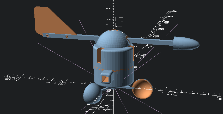
No weather station is complete without wind speed and wind direction sensors, so that's what I decided to embark on next. Since I had to wait for my new roll of filament, I decided to work on some of the design. Here is the proposed design that I came up with:

This design is loosely based off of some setups that I saw when doing some google image searches. I started with the anemometer cups. I found an OpenSCAD design for these on thingiverse http://www.thingiverse.com/thing:34644 and used that as my starting point. I designed all of the other parts around this. So the only part of this that I can say is not truly my design is that. There are 12 parts total that I printed for this:- 3 anemometer cups with arms
- Central cylinder that the cups mount to
- Bottom case with square mounting peg that holds the anemometer sensor
- wind speed rotor that holds the magnet for the sensor
- Top case that holds the wind direction vane
- The wind direction cap
- 2 wind vane arms to hold the tail fin and the nose cone
- The tail fin
- The nose cone
One last part that I have not designed yet which will be pretty simple is the internal wind direction rotor that will hold the magnet for the direction sensor.
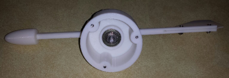
Here are some pics of the finished parts:
Wind direction vane inside showing 1 inch roller bearing
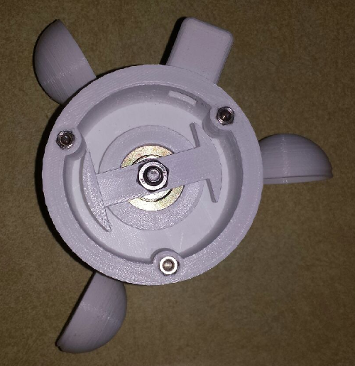
Anemometer inside showing the mounted rotor.
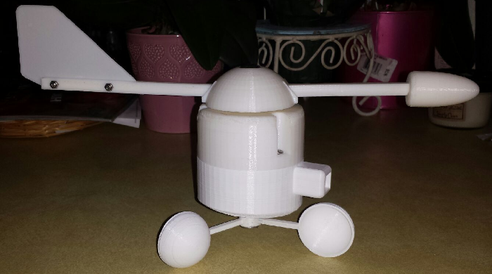
The full assembly
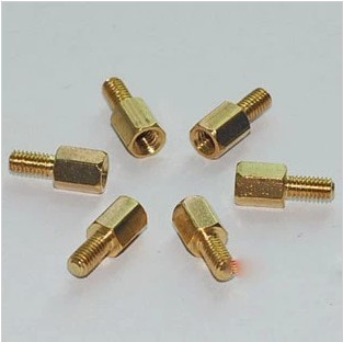
For the screw posts to hold the cap and base together, I took some stainless circuit board mounting posts similar to the ones below that I had in my parts bin and use my soldering iron to melt them into the holes. My guess is that the melted plastic took a good hold of the threaded end, so I doubt they are coming out.
All in all, the project is coming together nicely. Once I get a few more pieces together, I will post all of this on my thingiverse page and give the link to the group. I will post further details on this as I get things done. I always welcome comments and suggestion to my designs, so if you have any, feel free to post them here.
-
So after getting my 3D printer I was thinking of all the MySensors projects that I could build with it. One of the things that I had looked at previously was setting up a weather station for my setup. The problem was that I would have had to buy some commercial weather station hardware and try to convert it to work with MySensors. The hardware alone for these was a bit expensive, not to mention the work it would take to convert it.
Having a 3D printer now has opened new doors for this project. I started working on designs for the parts to this and have some good progress. I still need to work out some of the electronics, but that will come in time as I get parts built.
One of the first things was designing a tipping bucket rain gauge which I have some posts on in a topic under hardware in the forum. I still need to print some parts for this. Started printing some things and ran out of white filament. Just got my new roll in the other day, so I will most likely start these in the next couple days.
No weather station is complete without wind speed and wind direction sensors, so that's what I decided to embark on next. Since I had to wait for my new roll of filament, I decided to work on some of the design. Here is the proposed design that I came up with:
This design is loosely based off of some setups that I saw when doing some google image searches. I started with the anemometer cups. I found an OpenSCAD design for these on thingiverse http://www.thingiverse.com/thing:34644 and used that as my starting point. I designed all of the other parts around this. So the only part of this that I can say is not truly my design is that. There are 12 parts total that I printed for this:- 3 anemometer cups with arms
- Central cylinder that the cups mount to
- Bottom case with square mounting peg that holds the anemometer sensor
- wind speed rotor that holds the magnet for the sensor
- Top case that holds the wind direction vane
- The wind direction cap
- 2 wind vane arms to hold the tail fin and the nose cone
- The tail fin
- The nose cone
One last part that I have not designed yet which will be pretty simple is the internal wind direction rotor that will hold the magnet for the direction sensor.
Here are some pics of the finished parts:
Wind direction vane inside showing 1 inch roller bearing
Anemometer inside showing the mounted rotor.
The full assembly
For the screw posts to hold the cap and base together, I took some stainless circuit board mounting posts similar to the ones below that I had in my parts bin and use my soldering iron to melt them into the holes. My guess is that the melted plastic took a good hold of the threaded end, so I doubt they are coming out.
All in all, the project is coming together nicely. Once I get a few more pieces together, I will post all of this on my thingiverse page and give the link to the group. I will post further details on this as I get things done. I always welcome comments and suggestion to my designs, so if you have any, feel free to post them here.
@dbemowsk - nice work! Looking forward to follow this project!
-
@dbemowsk - nice work! Looking forward to follow this project!
@sundberg84 I should have the wind sensor finished by next week. I already have the reed switch I need for the wind speed sensor. The ones for the direction sensor needed to be smaller, so I ordered some 7mm magnetic reed switches today to use for that. I'll make the direction sensor board something like this:
-
@dbemowsk - nice work! Looking forward to follow this project!
@sundberg84 I have some of your new Rev 9 boards that I got recently that I will most likely be using for this project. Kudos on the boards.
-
@sundberg84 I have some of your new Rev 9 boards that I got recently that I will most likely be using for this project. Kudos on the boards.
@dbemowsk - maybe we could do some sort of basic PCB to use with your project later on and MySensors people can buy and assemble both PCB and 3d printed thereself. Well that for the future. Good luck!
-
So after getting my 3D printer I was thinking of all the MySensors projects that I could build with it. One of the things that I had looked at previously was setting up a weather station for my setup. The problem was that I would have had to buy some commercial weather station hardware and try to convert it to work with MySensors. The hardware alone for these was a bit expensive, not to mention the work it would take to convert it.
Having a 3D printer now has opened new doors for this project. I started working on designs for the parts to this and have some good progress. I still need to work out some of the electronics, but that will come in time as I get parts built.
One of the first things was designing a tipping bucket rain gauge which I have some posts on in a topic under hardware in the forum. I still need to print some parts for this. Started printing some things and ran out of white filament. Just got my new roll in the other day, so I will most likely start these in the next couple days.
No weather station is complete without wind speed and wind direction sensors, so that's what I decided to embark on next. Since I had to wait for my new roll of filament, I decided to work on some of the design. Here is the proposed design that I came up with:
This design is loosely based off of some setups that I saw when doing some google image searches. I started with the anemometer cups. I found an OpenSCAD design for these on thingiverse http://www.thingiverse.com/thing:34644 and used that as my starting point. I designed all of the other parts around this. So the only part of this that I can say is not truly my design is that. There are 12 parts total that I printed for this:- 3 anemometer cups with arms
- Central cylinder that the cups mount to
- Bottom case with square mounting peg that holds the anemometer sensor
- wind speed rotor that holds the magnet for the sensor
- Top case that holds the wind direction vane
- The wind direction cap
- 2 wind vane arms to hold the tail fin and the nose cone
- The tail fin
- The nose cone
One last part that I have not designed yet which will be pretty simple is the internal wind direction rotor that will hold the magnet for the direction sensor.
Here are some pics of the finished parts:
Wind direction vane inside showing 1 inch roller bearing
Anemometer inside showing the mounted rotor.
The full assembly
For the screw posts to hold the cap and base together, I took some stainless circuit board mounting posts similar to the ones below that I had in my parts bin and use my soldering iron to melt them into the holes. My guess is that the melted plastic took a good hold of the threaded end, so I doubt they are coming out.
All in all, the project is coming together nicely. Once I get a few more pieces together, I will post all of this on my thingiverse page and give the link to the group. I will post further details on this as I get things done. I always welcome comments and suggestion to my designs, so if you have any, feel free to post them here.
-
@dbemowsk awesome what you're doing in openscad! :+1:
I wonder if we could come up with a design that also incorporates a rain meter and all electronics...@Yveaux I have been working on the rain gauge that I will use with this. I will probably start posting the pics for the rain gauge in this thread from now on and just link the other thread to this one.
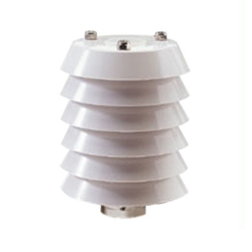
One other part that I haven't mentioned that I want to incorporate is a vented radiation shield like this to hold some of the sensors like temp, humidity, barometric pressure, etc.. I could possibly fit the MySensors board in this.
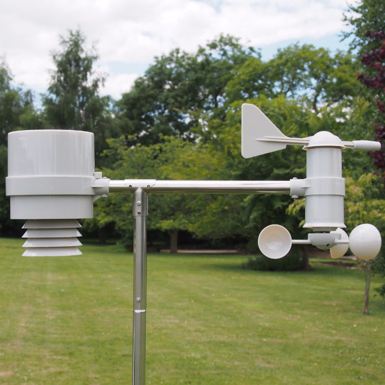
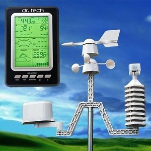
Just did a quick google image search on "home weather station" and found a few that I could possibly use as models for the design since the wind sensor parts are similar to mine:
-
@dbemowsk - maybe we could do some sort of basic PCB to use with your project later on and MySensors people can buy and assemble both PCB and 3d printed thereself. Well that for the future. Good luck!
@sundberg84 I love the idea of putting together a board for this. I would probably hold off though until I get the hardware built to know what we are dealing with. If we do it, it could be designed with connectors for all of the sensors and be set up as some sort of modular design so that people could build as much or as little of the project as they want.
-
@sundberg84 I love the idea of putting together a board for this. I would probably hold off though until I get the hardware built to know what we are dealing with. If we do it, it could be designed with connectors for all of the sensors and be set up as some sort of modular design so that people could build as much or as little of the project as they want.
@dbemowsk - sounds like a good plan!
-
Can I make a suggestion? Reverse the placement of the nuts to the top part, and the little machine screws to the bottom part of the housing. That way it will be easier to keep the water out as it will not creep in to the gap between the ABS and the screw. That capillary action will also work upside down, but good old gravity counters that to a great degree.
-
@Yveaux I have been working on the rain gauge that I will use with this. I will probably start posting the pics for the rain gauge in this thread from now on and just link the other thread to this one.
One other part that I haven't mentioned that I want to incorporate is a vented radiation shield like this to hold some of the sensors like temp, humidity, barometric pressure, etc.. I could possibly fit the MySensors board in this.
Just did a quick google image search on "home weather station" and found a few that I could possibly use as models for the design since the wind sensor parts are similar to mine:
@dbemowsk I have exactly the same weather station as the first one (Alecto DKW-2012 in my case).
I would very much like to have all sensors integrated into a single unit, not having single units (wind, rain, temp) interconnected with some bars.
This would also have a much higher WAF :nail_care: IMHO
Maybe I'd better sit down and drawn something to get the creativity flowing ;-)What material did you use to print it BTW?
-
Can I make a suggestion? Reverse the placement of the nuts to the top part, and the little machine screws to the bottom part of the housing. That way it will be easier to keep the water out as it will not creep in to the gap between the ABS and the screw. That capillary action will also work upside down, but good old gravity counters that to a great degree.
@DavidZH Good point. Reversing these should not be a big problem. Just a matter of re-designing the internal rotors that hold the magnets. I'd have to do that because one side has more room than the other. They are only like 15 minute prints anyway
Thanks for the suggestion.
-
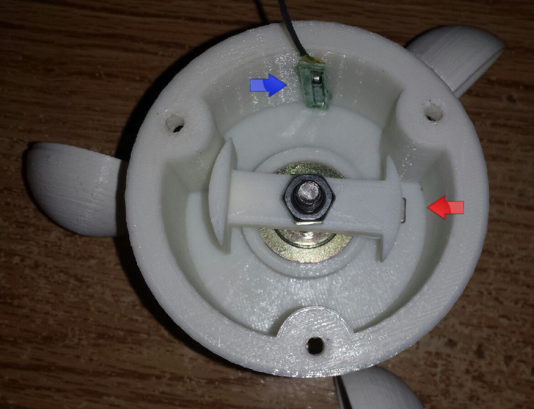
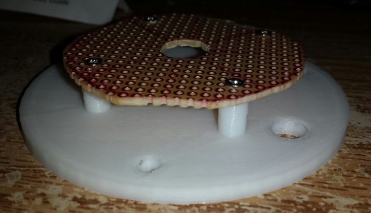
So Monday I should have my new reed switches and should be able to start working on the board for the wind sensors. For the anemometer, the setup is pretty simple. The rotor has a magnet (red arrow) that passes by the reed switch (blue arrow) to count the revolutions.
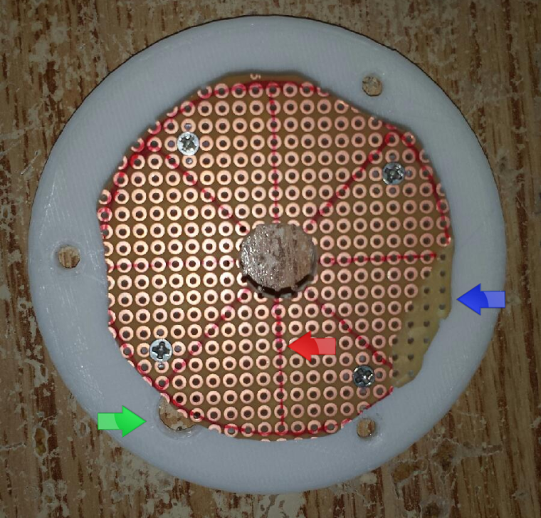
The reed switch wire for the anemometer will pass through the hole at the edge (green arrow) and connect to the direction rotor PCB. Had a small problem when I was cutting the board (blue arrow), but it should still be usable for the prototype. The red lines (red arrow) are where the reed switches will get mounted for the wind direction rotor.
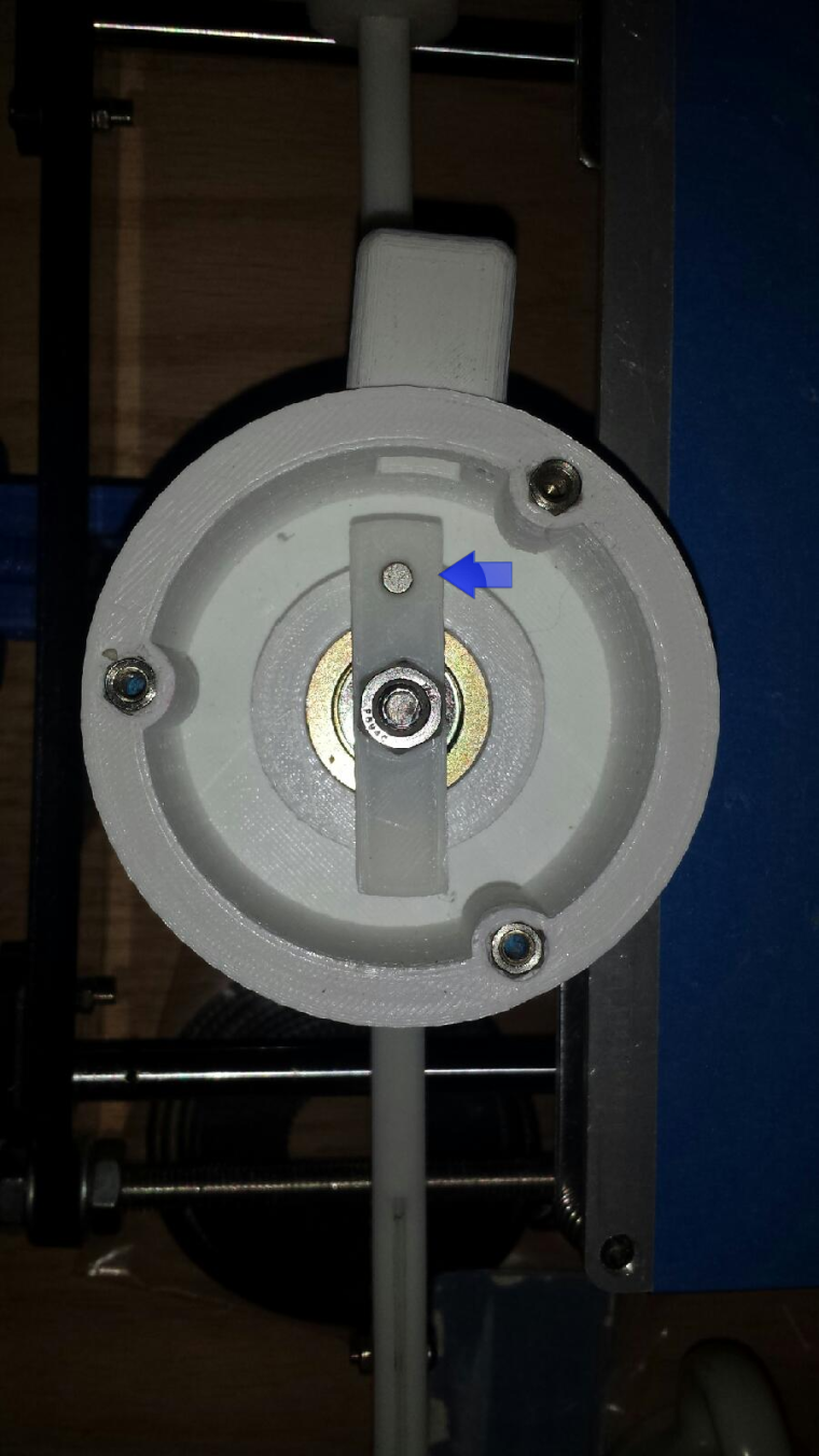
The direction rotor has a small round magnet (blue arrow) which should face the nose cone of the wind direction vane and will pass by the magnetic reed switches mounted on the round PCB
The circuit board mounting plate will get sandwiched between the top and bottom covers and have the main connection wire feed through the side hole near the wind direction magnet in the previous pic.
Later I will post the proposed schematic for how this will all connect to the pro mini. I will also hopefully have some test code for the setup.
-
So I was playing around a bit on the circuits.io website and came up with this for a test circuit. Each push button switch represents a reed switch for the direction rotor.
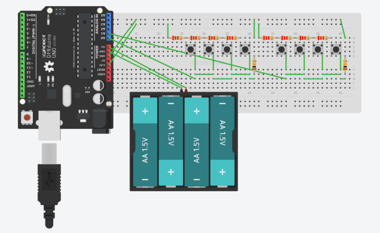
The idea is to separate the 8 reed switches into two banks which will only use 2 analog IO lines to handle all 8 switches. The first bank of reed switches will be for North, South, East and West. The second bank will be for Northeast, Southeast, Southwest and Northwest. My main reason for doing it this way was due to the fact that the MySensors library API uses V_DIRECTION for the wind direction and is a number between 0 and 360. I needed a way to get more accurate than just 0, 45, 90, 135, 180 etc... which I could do tying all of the reed switches to 1 analog IO line. With this design, I can catch the directions when the magnet is in-between 2 of the reed switches and activating both giving me another 1/8 step of accuracy.
Below is the code that I tested on the above circuit. The code should handle debouncing of the reed switches. With the reed switch and magnet rotor setup in place, the code should never reach a 999 value. It should always return a value between 0 and 337 based on the direction of the wind.
int old_NSEW = 0, old_NeSeSwNw = 0;

void setup() {
  Serial.begin(9600);
  pinMode(A0, INPUT);
  pinMode(A1, INPUT);
}

int getNSEW()
{
  int i, z, sum;
  int button;

  sum = 0;
  for (i=0; i < 4; i++)
  {
     sum += analogRead(A0);
  }
  z = sum / 4;
  //Serial.println(z);
  if (z > 1021) button = 999;
  else if (z > 357 && z < 361) button = 0;
  else if (z > 405 && z < 409) button = 90;
  else if (z > 467 && z < 471) button = 180;
  else if (z > 551 && z < 555) button = 270;
  else button = 999;

  return button;
}

int getNeSeSwNw()
{
  int i, z, sum;
  int button;

  sum = 0;
  for (i=0; i < 4; i++)
  {
     sum += analogRead(A1);
  }

  z = sum / 4;
  //Serial.println(z);
  if (z > 1021) button = 999;
  else if (z > 357 && z < 361) button = 45;
  else if (z > 405 && z < 409) button = 135;
  else if (z > 467 && z < 471) button = 225;
  else if (z > 551 && z < 555) button = 315;
  else button = 999;

  return button;
}


void loop ()
{
  int NSEW, NeSeSwNw, NSEW_curr, NeSeSwNw_curr, triggered_NSEW, triggered_NeSeSwNw;
  NSEW = getNSEW();
  NeSeSwNw = getNeSeSwNw();
  if (NSEW != old_NSEW)
  {
      delay(50);        // debounce
      NSEW_curr = getNSEW();

      if (NSEW == NSEW_curr)
      {
         old_NSEW = NSEW;
         triggered_NSEW = NSEW;
        if (NSEW == 999 || NeSeSwNw == 999) {
           triggered_NSEW = NSEW;
        } else if (NSEW < NeSeSwNw) {
           triggered_NSEW = ((NeSeSwNw - NSEW) / 2) + NSEW;
        } else {
           triggered_NSEW = NSEW - ((NSEW - NeSeSwNw) / 2);
        }
         Serial.println(triggered_NSEW);
      }
   }
  if (NeSeSwNw != old_NeSeSwNw)
  {
      delay(50);        // debounce
      NeSeSwNw_curr = getNeSeSwNw();

      if (NeSeSwNw == NeSeSwNw_curr)
      {
         old_NeSeSwNw = NeSeSwNw;
        if (NSEW == 999 || NeSeSwNw == 999) {
           triggered_NeSeSwNw = NeSeSwNw;
        } else if (NSEW < NeSeSwNw) {
           triggered_NeSeSwNw = ((NeSeSwNw - NSEW) / 2) + NeSeSwNw;
        } else {
           triggered_NeSeSwNw = NeSeSwNw - ((NSEW - NeSeSwNw) / 2);
        }
        Serial.println(triggered_NeSeSwNw);
      }
   }
}
Does anyone see any issues in this approach to the wind direction?
Next I plan on working on the code for the anemometer to calculate wind speed. I could possibly have that figured out later today.
-
Personally I think you may have issues with the position when magnet will be around the middle of 2 sensors because it could either trigger both or none of them so magnet strength will be crucial to your setup. I still think the optical sensor used by the other weather stations is a preferred solution
@gohan the diameter of the circuit board is 52mm or a radius of 26mm. From the center of the shaft to the center of the magnet is 17.75mm. The reed switches I ordered were 7mm long. I had to get shorter ones because of the tight space they will be in. The magnet's diameter is 4.25mm and it is a pretty strong neodymium magnet. Calculating the circumference to the center of where the magnet is mounted on the rotor, that is 111.5mm. Dividing that by 8 gives a distance between the reed switches of 13.94mm. I tested with a different reed switch that I had and found that the detection distance from magnet to reed switch is roughly 5mm plus or minus a smidge. The rotor should be fairly close to the reed switches if my calculations are correct. I can't say 100% till I get the reed switches and build the assembly, but I think I am going to be fine. I think worst case, I might have to get a slightly larger magnet, and even if I did it wouldn't have to be more than 1 to 2 millimeters bigger than the one I have.
-
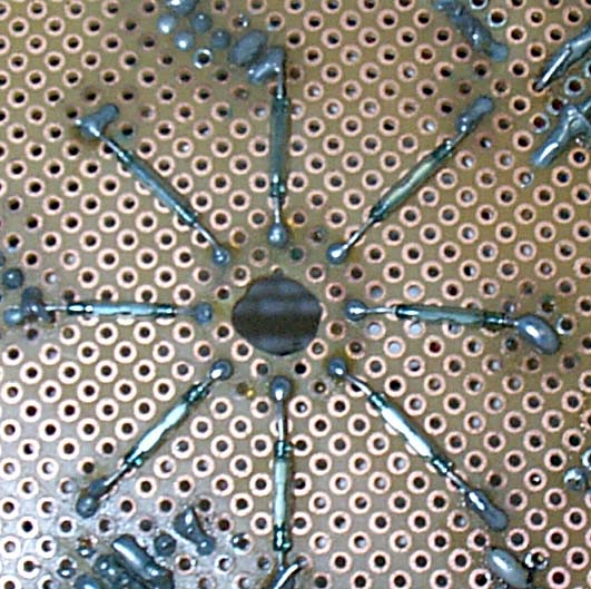
So here is an update on where I am at with the direction rotor assembly. I came up with the following proposed circuit board assembly based on my circuits.io layout from my previous post. All of the reed switches are in a circular configuration and alternate the 2 different switch banks seen in the above post.
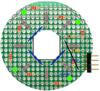
Following that diagram, here is the final prototype board. The only difference in the final board is that I used 3.3k resistors, as I was low on 2.2k's. I figured all I should have to do is make a couple adjustments to the code for the derived values when a reed switch was activated.
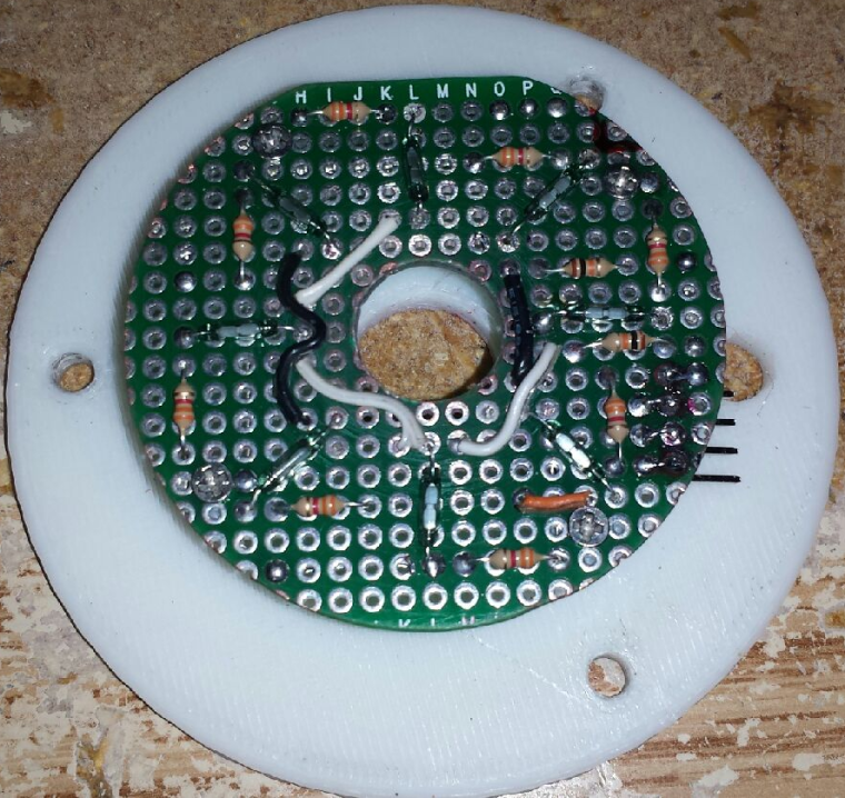
Even though the design seemed pretty solid, I seem to be having some issues with it. I have tried a few different rotor and magnet assemblies. All of the magnets are neodymium magnets that I got from various salvage operations. The order from left to right is the order that I tested them in.
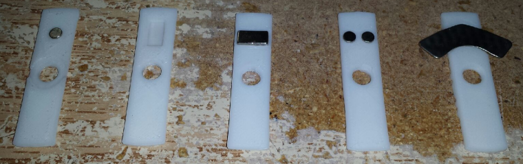
It appears that @gohan was correct about the first test rotor. Some of the other ones just seemed a bit erratic. There are a couple other things that I want to try, but I'm starting to look at some kind of 360 degree angle sensor to potentially use. I am wondering if anyone in the forum has done any kind of rotational angle sensing, and what sensor did you end up using?
Hello! It looks like you're interested in this conversation, but you don't have an account yet.
Getting fed up of having to scroll through the same posts each visit? When you register for an account, you'll always come back to exactly where you were before, and choose to be notified of new replies (either via email, or push notification). You'll also be able to save bookmarks and upvote posts to show your appreciation to other community members.
With your input, this post could be even better 💗
Register Login