[SOLVED] NodeMCU ESP8266 and SPI with NRF24L01 + SD card module - sanity errors?
-
Hi,
I have a problem which has been bothering me two evenings now; and I am just wondering if someone has a clever idea to get closer to the solution, or have a solution in general.
I have a NodeMCU ESP8266 setup as MQTT gateway using the default pin layout as described on https://www.mysensors.org/build/connect_radio. This works perfect, and have been doing various tests now with battery based sensors.
But, now I also want to create a backup system to a MicroSD card on this gateway using an MicroSD adapter. My receive() function will do these activities. Now the only problem is that I just cannot get the radio and SD card work together.
Even not when not including the SD.h (or other related) libraries. The moment the CS pin is removed from the breadboard, the NodeMCU almost instantly continues and the radio turns on.
These two evenings have been quite educational, but now it's time to get this to work :-). I also tested on another NodeMCU, which has the same issue. The SD card works standalone perfectly. Also with the radio connected it works perfect. It's just the radio that refuses to work and continues to give:
0;255;3;0;9;TSM:INIT
0;255;3;0;9;RF24:write register, reg=0, value=14
0;255;3;0;9;RF24:write register, reg=3, value=3
0;255;3;0;9;RF24:write register, reg=4, value=95
0;255;3;0;9;RF24:write register, reg=5, value=76
0;255;3;0;9;RF24:write register, reg=6, value=39
0;255;3;0;9;RF24:write register, reg=16, value=115
0;255;3;0;9;RF24:write register, reg=29, value=6
0;255;3;0;9;RF24:read register, reg=6, value=0
0;255;3;0;9;RF24:read register, reg=5, value=0
0;255;3;0;9;!RF24:INIT:SANCHK FAIL
0;255;3;0;9;!TSM:INIT:TSP FAIL
0;255;3;0;9;TSM:FAIL:CNT=7
0;255;3;0;9;TSM:FAIL:PDT
0;255;3;0;9;RF24:write register, reg=0, value=12
The CS of the radio is on D8 and the CS of the SD reader is D4. This matches with the pins as seen below (according to: https://pradeepsinghblog.files.wordpress.com/2016/04/nodemcu_pins.png?w=616)
This results from the before() function (serial print from the program):
RF 24 CS PIN
15
SD CS PIN
2
pins low
SD_CS_PIN is HIGH - GOOD
MY_RF24_CS_PIN is LOW - GOOD
The SD_CS pin is put to HIGH in the before() and pinmode are set in the before function:
pinMode (SD_CS_PIN, OUTPUT); digitalWrite (SD_CS_PIN, HIGH); pinMode (MY_RF24_CS_PIN, OUTPUT); digitalWrite (MY_RF24_CS_PIN, LOW );Remember: The SD libraries are not used at all. No begin() functions of any kind are called.
This is what I have learned over the evenings, and I think this is all what it should be. The only thing I can think of is that the SD module just ignores the CS value.
Hope that someone has a clue what could solve this issue. I am out of ideas right now.
-
Hi Yveaux,
I don't know what comes after quadruple (quintuble? :)) but I checked the wires many times. Radio works perfect without SD card reader. SD card worked with radio connected - but then the radio does not work anymore.
I made a fritzing of my setup, just to spot any errors, just to go check each connection once more.
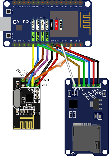
One thing I can think of is that the GPIO15 is a hardware CS (HCS), while my D4 is not. But every example I see on the internet says that practically any pin can be the CS pin?
Update
More searching let me to this topic: https://forum.arduino.cc/index.php?topic=360718.0 which I think might be the case. Unfortunately, I do not have the tools to apply this fix I think.

-
Re: NodeMCU ESP8266 and SPI with NRF24L01 + SD card module - sanity errors?
Separate reply just for searching purposes:
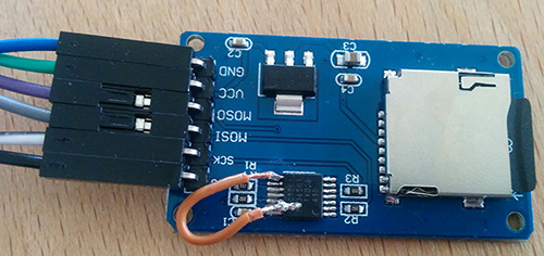
It worked :-)! Now it's working perfect without changing a single line of code or changing wires. I took the risk of destroying the module, but otherwise it's useless anyway for my project. I managed to use a knife to take a few mm's of pin 13 up and then to solder a wire to pin 8 and pin 13. As described in the linked topic.
My SD backup system one step closer! :D
-
Re: NodeMCU ESP8266 and SPI with NRF24L01 + SD card module - sanity errors?
Separate reply just for searching purposes:
It worked :-)! Now it's working perfect without changing a single line of code or changing wires. I took the risk of destroying the module, but otherwise it's useless anyway for my project. I managed to use a knife to take a few mm's of pin 13 up and then to solder a wire to pin 8 and pin 13. As described in the linked topic.
My SD backup system one step closer! :D
-
@Kokosnoot great to hear you solved it!
Crappy design module once more...
Usually I always start googling schematics of any new modules I buy, just to prevent surprises like this! -
@Yveaux sometimes I just wonder if the designer of a module just copied another one just by looking at it and then put it to production without even testing it.
-
This post is deleted!
Hello! It looks like you're interested in this conversation, but you don't have an account yet.
Getting fed up of having to scroll through the same posts each visit? When you register for an account, you'll always come back to exactly where you were before, and choose to be notified of new replies (either via email, or push notification). You'll also be able to save bookmarks and upvote posts to show your appreciation to other community members.
With your input, this post could be even better 💗
Register Login