nRF5 action!
-
Around 30 feet, through some walls, but at 2mbps. I realize that's not very far, but even so the measured packet loss (informal testing) is pretty high at that speed. I can see why most people default to 250kbps instead.
I don't have the 840 dev kit yet, mostly because I don't see anyother 840 modules on the market right now.
@NeverDie Did you manage to get more than 10m ? maybe by another modules.
I thought the nrf52 will have better range !
-
@NeverDie
Exactly. There are two pads labelled SWD and SWC, originally meant for pogo pins.
I patched them with wires to the pin header.
Programming with a Chinese STLink V2 clone works flawlessly.@Uhrheber I am a bit confused. To program the nRF52 from eByte I need a special programmer but they are expensive. So you mean you used a clone StLink V2 and it worked fine ?
I found this.
-
@Uhrheber I am a bit confused. To program the nRF52 from eByte I need a special programmer but they are expensive. So you mean you used a clone StLink V2 and it worked fine ?
I found this.
@ahmedadelhosni
Sure, I'm using a similar one.
Why wouldn't it work? The nrf52 is an ARM Mx, like the ST chips. The programming interface is the same. You could also use one of the many other ARM programmers, like J-Link, or nearly any JTAG programmer supported by OpenOCD.Just follow this guide: https://www.openhardware.io/view/376/MySensors-NRF5-Platform
And: https://github.com/sandeepmistry/arduino-nRF5/#installing -
@ahmedadelhosni
Sure, I'm using a similar one.
Why wouldn't it work? The nrf52 is an ARM Mx, like the ST chips. The programming interface is the same. You could also use one of the many other ARM programmers, like J-Link, or nearly any JTAG programmer supported by OpenOCD.Just follow this guide: https://www.openhardware.io/view/376/MySensors-NRF5-Platform
And: https://github.com/sandeepmistry/arduino-nRF5/#installing@Uhrheber Great. Thanks for the help.
So if I understand well. If I have a TIVA board like TM4C123G Launchpad and it is ARM Mx also, then I can use it to program my nRF ?
This is the datasheet for the board : http://www.ti.com/lit/ug/spmu296/spmu296.pdf
I searched and found those links describing how to use the Launchad but I am not sure whether this will work for nRF also or not.
http://processors.wiki.ti.com/index.php/Stellaris_LM4F120_LaunchPad_Debug_How_To
http://ucsolutions.blogspot.com.eg/2014/08/ti-launchpad-as-external-debugger-with.htmlThanks.
-
@Uhrheber Great. Thanks for the help.
So if I understand well. If I have a TIVA board like TM4C123G Launchpad and it is ARM Mx also, then I can use it to program my nRF ?
This is the datasheet for the board : http://www.ti.com/lit/ug/spmu296/spmu296.pdf
I searched and found those links describing how to use the Launchad but I am not sure whether this will work for nRF also or not.
http://processors.wiki.ti.com/index.php/Stellaris_LM4F120_LaunchPad_Debug_How_To
http://ucsolutions.blogspot.com.eg/2014/08/ti-launchpad-as-external-debugger-with.htmlThanks.
@ahmedadelhosni said in nRF5 Bluetooth action!:
@Uhrheber Great. Thanks for the help.
So if I understand well. If I have a TIVA board like TM4C123G Launchpad and it is ARM Mx also, then I can use it to program my nRF ?
This is the datasheet for the board : http://www.ti.com/lit/ug/spmu296/spmu296.pdf
I searched and found those links describing how to use the Launchad but I am not sure whether this will work for nRF also or not.
http://processors.wiki.ti.com/index.php/Stellaris_LM4F120_LaunchPad_Debug_How_To
http://ucsolutions.blogspot.com.eg/2014/08/ti-launchpad-as-external-debugger-with.htmlThanks.
I think it's a question of the licence of the programmer that is on your board.
For example the J-Link version on the NRF52 DK is only allowed to program NRF52 and NRF51 chips. It's logic because the NRF52DK is just over 30$ while a J-Link programmer is x00$.
You have pins SWDIO and SWDCLK on pins PC0 and PC1 of your board so just try it and you will know :) -
Guys, your best bet is to reflash STM32 Bluepill into BlackMagicProbe.
It's awesome!
https://medium.com/@paramaggarwal/converting-an-stm32f103-board-to-a-black-magic-probe-c013cf2cc38c -
Anyhow, the basic question remains and boils down to this: Can I have both
    // Enable interrupt
  NVIC_SetPriority(LPCOMP_IRQn, 15);
  NVIC_ClearPendingIRQ(LPCOMP_IRQn);
  NVIC_EnableIRQ(LPCOMP_IRQn);
AND an equivalent incantation for the RTC both active at the same time? Or am I forced into having it be just one or the other?
@NeverDie said in nRF5 Bluetooth action!:
Anyhow, the basic question remains and boils down to this: Can I have both
    // Enable interrupt
  NVIC_SetPriority(LPCOMP_IRQn, 15);
  NVIC_ClearPendingIRQ(LPCOMP_IRQn);
  NVIC_EnableIRQ(LPCOMP_IRQn);
AND an equivalent incantation for the RTC both active at the same time? Or am I forced into having it be just one or the other?
@d00616 Any thoughts or comments regarding this?
-
@NeverDie said in nRF5 Bluetooth action!:
Anyhow, the basic question remains and boils down to this: Can I have both
    // Enable interrupt
  NVIC_SetPriority(LPCOMP_IRQn, 15);
  NVIC_ClearPendingIRQ(LPCOMP_IRQn);
  NVIC_EnableIRQ(LPCOMP_IRQn);
AND an equivalent incantation for the RTC both active at the same time? Or am I forced into having it be just one or the other?
@d00616 Any thoughts or comments regarding this?
@NeverDie said in nRF5 Bluetooth action!:
@d00616 Any thoughts or comments regarding this?
Sorry, I can't help here. Maybe, the interrupt priority can be used only once and you have to use another priority for RTC or LPCOMP.
-
I tried out the Fanstel BT832X (i.e. nRF52832 with PA and LNA) today:
Good news:
- Even without the PA turned on, the range seems a lot better than if transmitting from an Ebyte module.
- Also, I've confirmed that it comes with DCDC built-in.
- With the PA turned on, the range is comparable to, and perhaps even better than, the RFaxis I reviewed earlier in this thread.
With the PA turned on, it consumes about 250ma.
-
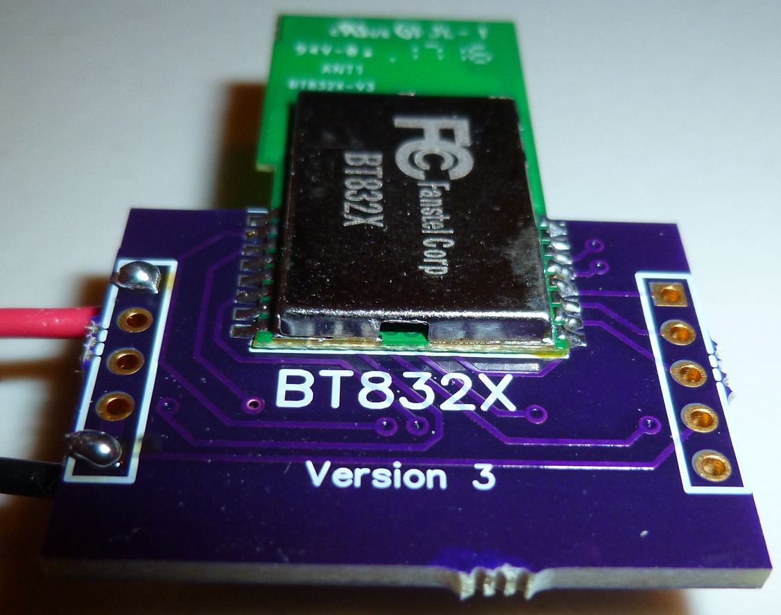
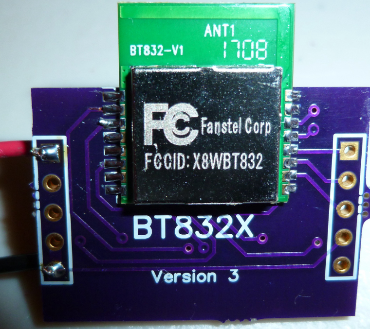
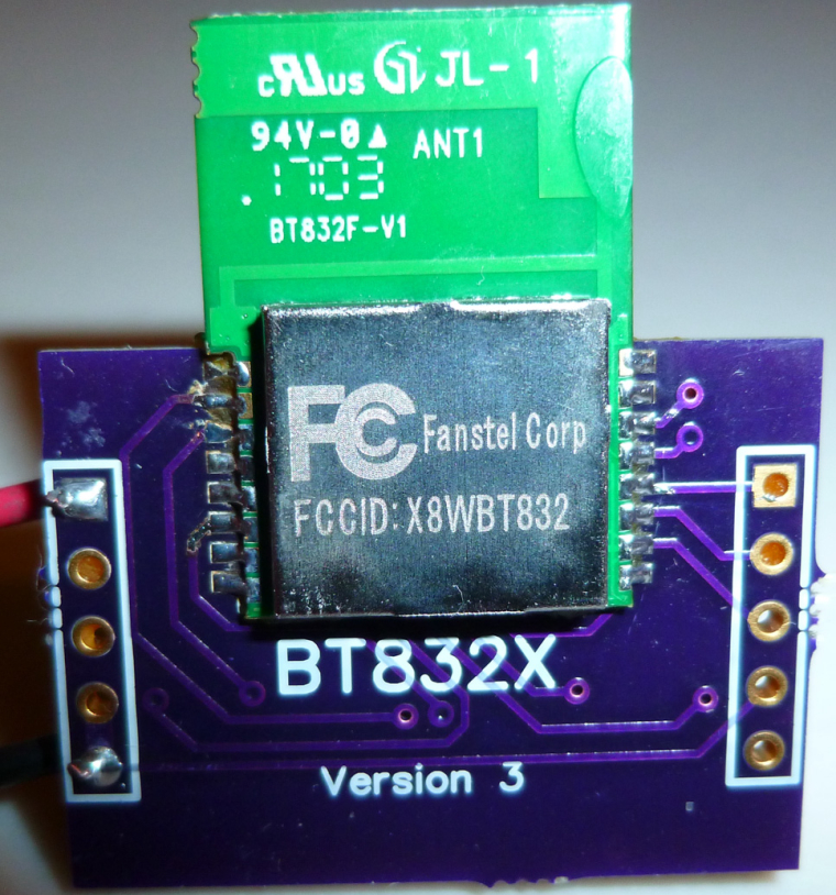
@d00616 I hooked up the Fanstel BT832A. Although it appeared to flash and verify correctly, I couldn't get it to do anything--not even blink. Is there any chance that it's downsized flash/memory has something to do with it? "Flash/RAM memories in BT832 are 512KB/64KB. They are 192KB/24KB in BT832A." So, as an experiment, I hooked up a BT832 in its place on the same board, and it's able to transmit and blink just fine. In total, the only differences between the two are:
- Cortex M4F in BT832 has hardware DSP and floating point instructions. Cortex M4 in BT832A has hardware DSP instructions but it does not have floating point unit to support hardware instruction.
- Flash/RAM memories in BT832 are 512KB/64KB. They are 192KB/24KB in BT832A.
- BT832 has NFC tag interface. BT832A does not have NFC tag
interface.
I think we can rule out #3. So, if it isn't #2, then is perhaps #1 a factor? I wouldn't think so.
The solder connections seemed correct. I suppose it's possible I simply got a bad module, but I'm doubtful that's it.
Here's a photo of it installed on a BT832X board, which is pin-for-pin compatible:
-
@d00616 I hooked up the Fanstel BT832A. Although it appeared to flash and verify correctly, I couldn't get it to do anything--not even blink. Is there any chance that it's downsized flash/memory has something to do with it? "Flash/RAM memories in BT832 are 512KB/64KB. They are 192KB/24KB in BT832A." So, as an experiment, I hooked up a BT832 in its place on the same board, and it's able to transmit and blink just fine. In total, the only differences between the two are:
- Cortex M4F in BT832 has hardware DSP and floating point instructions. Cortex M4 in BT832A has hardware DSP instructions but it does not have floating point unit to support hardware instruction.
- Flash/RAM memories in BT832 are 512KB/64KB. They are 192KB/24KB in BT832A.
- BT832 has NFC tag interface. BT832A does not have NFC tag
interface.
I think we can rule out #3. So, if it isn't #2, then is perhaps #1 a factor? I wouldn't think so.
The solder connections seemed correct. I suppose it's possible I simply got a bad module, but I'm doubtful that's it.
Here's a photo of it installed on a BT832X board, which is pin-for-pin compatible:
@NeverDie said in nRF5 Bluetooth action!:
I think we can rule out #3. So, if it isn't #2, then is perhaps #1 a factor? I wouldn't think so.
I think, you have to do more things:
- Change compiler attributes to disable FPU support
- Change the memory layout in linker scripts. Look into boards definition. Linker scripts are placed under ./cores/nRF5/SDK/components/toolchain/gcc/ The SDK14 has scripts supporting the nrf52810
- The SDK14 has an dedicated startup code (gcc_startup_nrf52810.S), I don't know if this relevant for arduino-nrf5
I think there is more to do than compile the code. I think the SDK code for arduino-nrf5 must be updated to SDK 14, then a nre MCU must be defined.
I have compared the startup code. The difference is in the interrupt vector. It should work with the NRF52832 startup code, but the linker script must be changed.
-
@NeverDie said in nRF5 Bluetooth action!:
I think we can rule out #3. So, if it isn't #2, then is perhaps #1 a factor? I wouldn't think so.
I think, you have to do more things:
- Change compiler attributes to disable FPU support
- Change the memory layout in linker scripts. Look into boards definition. Linker scripts are placed under ./cores/nRF5/SDK/components/toolchain/gcc/ The SDK14 has scripts supporting the nrf52810
- The SDK14 has an dedicated startup code (gcc_startup_nrf52810.S), I don't know if this relevant for arduino-nrf5
I think there is more to do than compile the code. I think the SDK code for arduino-nrf5 must be updated to SDK 14, then a nre MCU must be defined.
I have compared the startup code. The difference is in the interrupt vector. It should work with the NRF52832 startup code, but the linker script must be changed.
@d00616 Also, at least so far, I haven't been able to get the Fanstel modules to receive anything. At first I thought it must be an LNA thing, but I tried it just now on a Fanstel module without LNA, and although it can transmit and blink just fine, the regular receive code isn't working. Any theories on that?
-
@d00616 Also, at least so far, I haven't been able to get the Fanstel modules to receive anything. At first I thought it must be an LNA thing, but I tried it just now on a Fanstel module without LNA, and although it can transmit and blink just fine, the regular receive code isn't working. Any theories on that?
@NeverDie said in nRF5 Bluetooth action!:
@d00616 Also, at least so far, I haven't been able to get the Fanstel modules to receive anything. At first I thought it must be an LNA thing, but I tried it just now on a Fanstel module without LNA, and although it can transmit and blink just fine, the regular receive code isn't working. Any theories on that?
I think this could be the memory layout -> linker script. My try to port Arduino to nrf51 in 2014 is failed at the same state. Blink was ok. Using something with memory are failed. The reason was a wrong linker script. At this time Nordic hasen't released (L)GPG compatible scripts.
Edit: I think it's possible to add the 82810 to https://github.com/mysensors/ArduinoHwNRF5 by changing the board definition and add the missing linker script into the variant folder.
-
@NeverDie said in nRF5 Bluetooth action!:
@d00616 Also, at least so far, I haven't been able to get the Fanstel modules to receive anything. At first I thought it must be an LNA thing, but I tried it just now on a Fanstel module without LNA, and although it can transmit and blink just fine, the regular receive code isn't working. Any theories on that?
I think this could be the memory layout -> linker script. My try to port Arduino to nrf51 in 2014 is failed at the same state. Blink was ok. Using something with memory are failed. The reason was a wrong linker script. At this time Nordic hasen't released (L)GPG compatible scripts.
Edit: I think it's possible to add the 82810 to https://github.com/mysensors/ArduinoHwNRF5 by changing the board definition and add the missing linker script into the variant folder.
@d00616 I'm puzzled then. The module that you are using (https://www.aliexpress.com/item/NRF52832-Mini-Development-Board-Gold-Core-board-Wireless-Bluetooth-Transceiver-Module/32798618219.html?spm=2114.search0204.3.1.BEAy98&ws_ab_test=searchweb0_0,searchweb201602_4_10152_10065_10151_5700015_5620015_10130_10068_10344_10345_10547_10342_10546_10343_10340_10341_10548_10545_10541_10307_5640015_10060_10155_10154_10056_10055_10539_10538_5370015_10537_10536_10059_10534_10533_100031_10103_10102_10142_10107_10324_10325_5760015_10084_10083_10178_5750015_10312_10313_10314_10073_5630015,searchweb201603_30,ppcSwitch_4_ppcChannel&btsid=011daf01-f75a-4448-9202-405ef9dcacd9&algo_expid=acb605b8-ed11-4497-8757-d77cd4b3550b-0&algo_pvid=acb605b8-ed11-4497-8757-d77cd4b3550b) allegedly comes with 512k flash and 64k ram. So, what, if any, difference is there between that and the Fanstel module with the same amount of flash and ram?
-
OK, I need to confirm it, but I have a theory now that the Fanstel modules don't have 32K clock crystals in them. That would explain why that have pinouts for XTAL1 and XTAL2. It might also be hanging my code, which assumes there is a clock crystal and tries to turn it on.
My using pin P0.02 to control the LED might be a deadly brew that causes the hang. I'll post a follow-up if that's what turns out to be the actual root of what superficially seemed like an "Rx problem." -
It's confirmed. Son of a gun, they don't have the 32K clock crystal on the module. On the datasheet, it says that for battery operation, "We suggest adding a 32.768 kHz crystal and 2 capacitors as shown in the upper left corner of the evaluation board schematics."
I'll add pads for it on the breakout board.
-
OK, I need to confirm it, but I have a theory now that the Fanstel modules don't have 32K clock crystals in them. That would explain why that have pinouts for XTAL1 and XTAL2. It might also be hanging my code, which assumes there is a clock crystal and tries to turn it on.
My using pin P0.02 to control the LED might be a deadly brew that causes the hang. I'll post a follow-up if that's what turns out to be the actual root of what superficially seemed like an "Rx problem."@NeverDie said in nRF5 Bluetooth action!:
My using pin P0.02 to control the LED might be a deadly brew that causes the hang.
Correction: Use of P0.02 to control the LED shouldn't be a problem, as it corresponds to AIN0 and isn't involved in XTAL. Therefore, I edited the original post to strike-through this sentence.
-
Good news! Switching over to the RC oscillator totally fixed the problem. Both the Fanstel BT832 and BT832X now receive just fine. :)
-
In fact, both the Fanstel BT832 and the BT832X (with no LNA turned on) have much better receive range than an Ebyte module. They are head and shoulders better. In turn the BT832X (again, even with no LNA turned on) has a noticeably better receive range than the BT832.
So, at this point, I'm sold on the Fanstel modules for the most common uses. The Fanstel modules also have a smaller footprint than the Ebyte modules. The Ebyte modules might be better for those cases where you need a lot of easily accessible pins to do something, but that's about it I think.