nRF5 action!
-
Is signing soft supported or not yet ?
The personalizer sketch do not have hash define for the NRF52.
@ahmedadelhosni pull requests are always welcome.
-
Is signing soft supported or not yet ?
The personalizer sketch do not have hash define for the NRF52.
@ahmedadelhosni said in nRF5 Bluetooth action!:
Is signing soft supported or not yet ?
The personalizer sketch do not have hash define for the NRF52.The security personalizer is working with the NRF5X. Random numbers for the Soft Signing are generated with the internal AES hardware, seeded with the hardware number generator. This allows a fast and secure nonce generation.
At the Moment the NRF5 with Soft Signing is not at the same level like the ATSHA204, because the read back protection is not enabled. If you want to do this, you have to add some code.
-
What else should I turn-off to save power during sleep?
Presently, I turn-off these things: the radio, NFC, the high frequency clock, and uarte, Meanwhile, the low frequency clock is working.
Presently getting a sleep current drain of apprxoimately 2.8 microamps.
-
What else should I turn-off to save power during sleep?
Presently, I turn-off these things: the radio, NFC, the high frequency clock, and uarte, Meanwhile, the low frequency clock is working.
Presently getting a sleep current drain of apprxoimately 2.8 microamps.
@NeverDie said in nRF5 Bluetooth action!:
What else should I turn-off to save power during sleep?
Presently, I turn-off these things: the radio, NFC, the high frequency clock, and uarte, Meanwhile, the low frequency clock is working.
Presently getting a sleep current drain of apprxoimately 2.8 microamps.
Which chip are you talking about ?
-
nRF52832. I'm guessing the same will apply to the nRF51822, except for the NFC (which the nRF51822 doesn't have).
-
I should probably add that the 2.8ua is with the RTC and LPCOMP running. So, maybe it's already as low as it can go, I don't know. Just wondering if there are any other obvious suspects I should try turning off. I'll try i2C and SPI to see if it makes a difference... Not sure, but maybe SPI gets initialized through the header file without my even being aware of it.
-
Well, it could be within the bounds of measurement error, but it appears that dropping I2c and SPI has reduced the drain to 2.6ua.
@NeverDie said in nRF5 Bluetooth action!:
Well, it could be within the bounds of measurement error, but it appears that dropping I2c and SPI has reduced the drain to 2.6ua.
Is I2C or SPI used somewhere in your code?
-
@NeverDie said in nRF5 Bluetooth action!:
Well, it could be within the bounds of measurement error, but it appears that dropping I2c and SPI has reduced the drain to 2.6ua.
Is I2C or SPI used somewhere in your code?
@d00616 said in nRF5 Bluetooth action!:
@NeverDie said in nRF5 Bluetooth action!:
Well, it could be within the bounds of measurement error, but it appears that dropping I2c and SPI has reduced the drain to 2.6ua.
Is I2C or SPI used somewhere in your code?
Not in the current test code that I'm running.
-
@d00616 said in nRF5 Bluetooth action!:
@NeverDie said in nRF5 Bluetooth action!:
Well, it could be within the bounds of measurement error, but it appears that dropping I2c and SPI has reduced the drain to 2.6ua.
Is I2C or SPI used somewhere in your code?
Not in the current test code that I'm running.
@NeverDie said in nRF5 Bluetooth action!:
Not in the current test code that I'm running.
Interesting. The SPI is rated with <1µA idle current. TWI has no idle current in the datasheet.
-
@NeverDie said in nRF5 Bluetooth action!:
Not in the current test code that I'm running.
Interesting. The SPI is rated with <1µA idle current. TWI has no idle current in the datasheet.
-
So far, UARTE is the biggest offender. Turning off and disabling that saves a lot of current.
-
So, here is code which works! Many thanks to @d00616 and others for their helpful comments above.
To keep from distracting, I stripped out the radio code, but you can easily insert your favorite brand of that.
Basically, the sketch blinks an LED very briefly once every 5 seconds. Between blinks, it sleeps. However, if a leak is detected (which is equivalent to a button push), it wakes up immediately and blinks a lot. It runs on both nRF52832 and nRF51822. The sleep current is ~2.6ua on an nRF52832. To get sleep current that low, it is using the Low Power Comparator (LPCOMP) to watch for a change on the leak detector pin while the CPU sleeps.
I haven't yet measured the sleep current consumption on an nRF51822, but I expect it would be something comparable.
//This sketch is applicable to Coincell Multisensor nRF51822, version 10 #define MY_CORE_ONLY #define IS_NRF51 //true iff the target is an nRF51. If an nRF52, then comment this line out! #define I2C_INTERRUPT_PIN 3 #define LEAK_DETECTION_PIN 2 #include <nrf.h> #include <MySensors.h> volatile bool button_pressed=false; void blinkityBlink(uint8_t pulses, uint8_t repetitions) { for (int x=0;x<repetitions;x++) { for (int i=0;i<pulses;i++) { digitalWrite(LED_BUILTIN,HIGH); wait(20); digitalWrite(LED_BUILTIN,LOW); wait(100); } wait(500); } } void disableNfc() { //only applied to nRF52 #ifndef IS_NRF51 //Make pins 9 and 10 usable as GPIO pins. NRF_NFCT->TASKS_DISABLE=1; //disable NFC NRF_NVMC->CONFIG=1; // Write enable the UICR NRF_UICR->NFCPINS=0; //Make pins 9 and 10 usable as GPIO pins. NRF_NVMC->CONFIG=0; // Put the UICR back into read-only mode. #endif } void turnOffRadio() { NRF_RADIO->TASKS_DISABLE=1; while (!(NRF_RADIO->EVENTS_DISABLED)) {} //until radio is confirmed disabled } void turnOffUarte0() { #ifndef IS_NRF51 NRF_UARTE0->TASKS_STOPRX = 1; NRF_UARTE0->TASKS_STOPTX = 1; NRF_UARTE0->TASKS_SUSPEND = 1; NRF_UARTE0->ENABLE=0; //disable UART0 while (NRF_UARTE0->ENABLE!=0) {}; //wait until UART0 is confirmed disabled. #endif #ifdef IS_NRF51 NRF_UART0->TASKS_STOPRX = 1; NRF_UART0->TASKS_STOPTX = 1; NRF_UART0->TASKS_SUSPEND = 1; NRF_UART0->ENABLE=0; //disable UART0 while (NRF_UART0->ENABLE!=0) {}; //wait until UART0 is confirmed disabled. #endif } void turnOffAdc() { #ifndef IS_NRF51 if (NRF_SAADC->ENABLE) { //if enabled, then disable the SAADC NRF_SAADC->TASKS_STOP=1; while (NRF_SAADC->EVENTS_STOPPED) {} //wait until stopping of SAADC is confirmed NRF_SAADC->ENABLE=0; //disable the SAADC while (NRF_SAADC->ENABLE) {} //wait until the disable is confirmed } #endif } void turnOffHighFrequencyClock() { NRF_CLOCK->TASKS_HFCLKSTOP = 1; while ((NRF_CLOCK->HFCLKSTAT) & 0x0100) {} //wait as long as HF clock is still running. } void mySleepPrepare() { turnOffHighFrequencyClock(); turnOffRadio(); turnOffUarte0(); } void activateLpComp() { //NRF_LPCOMP->PSEL=1; // monitor AIN1 (pin P0.03 on nRF52832 test board). //while (!(NRF_LPCOMP->PSEL==1)) {} //wait until confirmed NRF_LPCOMP->PSEL=3; // monitor AIN3 (pin P0.02 on nRF51822 for coincell_multisensor_v10) while (!(NRF_LPCOMP->PSEL==3)) {} //wait until confirmed NRF_LPCOMP->REFSEL=1; // choose 1/4 VDD as the reference voltage while (!(NRF_LPCOMP->REFSEL==1)) {} //wait until confirmed NRF_LPCOMP->ANADETECT=1; //detect UP events. while (NRF_LPCOMP->ANADETECT!=1) {} //wait until confirmed NRF_LPCOMP->INTENSET=B0100; //Enable interrupt for UP event while (!(NRF_LPCOMP->INTENSET==B0100)) {} //wait until confirmed NRF_LPCOMP->ENABLE=1; //Enable LPCOMP while (!(NRF_LPCOMP->ENABLE==1)) {} //wait until confirmed NRF_LPCOMP->TASKS_START=1; //start the LPCOMP while (!(NRF_LPCOMP->EVENTS_READY)) {} //wait until ready NVIC_SetPriority(LPCOMP_IRQn, 15); NVIC_ClearPendingIRQ(LPCOMP_IRQn); NVIC_EnableIRQ(LPCOMP_IRQn); } void suspendLpComp() { //suspend getting more interrupts from LPCOMP before the first interrupt can be handled if ((NRF_LPCOMP->ENABLE) && (NRF_LPCOMP->EVENTS_READY)) { //if LPCOMP is enabled NRF_LPCOMP->INTENCLR=B0100; //disable interrupt from LPCOMP while (NRF_LPCOMP->INTENCLR==B0100) {} //wait until confirmed } } void resumeLpComp() { //suspend getting interrupts from LPCOMP NRF_LPCOMP->INTENSET=B0100; //Enable interrupt for UP event while (!(NRF_LPCOMP->INTENSET==B0100)) {} //wait until confirmed } void setup() { hwInit(); hwPinMode(LED_BUILTIN,OUTPUT_D0H1); disableNfc(); turnOffAdc(); activateLpComp(); blinkityBlink(2,1); //Signify end of setup with two quick pulses. mySleepPrepare(); button_pressed=false; } void loop() { sleep(5000); //sleep for 5 seconds. mySleepPrepare(); //An ounce of prevention: Turn-off HF clock, etc, ASAP to save power, just in case the library's sleep() routine resumed them. if (button_pressed) { //if a leak is detected suspendLpComp(); //suspend LPCOMP to prevent multiple interrupts blinkityBlink(10,3); //blink a lot to show that a leak was detected. button_pressed=false; //Clear the semaphore NRF_LPCOMP->EVENTS_UP=0; //Clear the semaphore resumeLpComp(); //operations of LPCOMP were suspended after detecting the LPCOMP iterrupt } else { blinkityBlink(1,1); //otherwise, just one short blink to indicate the wakeup was scheduled by the RTC } } // * Reset events and read back on nRF52 //* http://infocenter.nordicsemi.com/pdf/nRF52_Series_Migration_v1.0.pdf #if __CORTEX_M == 0x04 #define NRF5_RESET_EVENT(event) \ event = 0; \ (void)event #else #define NRF5_RESET_EVENT(event) event = 0 #endif // This must be in one line extern "C" { void LPCOMP_IRQHandler(void) {button_pressed=true; NRF5_RESET_EVENT(NRF_LPCOMP->EVENTS_UP); NRF_LPCOMP->EVENTS_UP=0; MY_HW_RTC->CC[0]=(MY_HW_RTC->COUNTER+2);}} -
So, here is code which works! Many thanks to @d00616 and others for their helpful comments above.
To keep from distracting, I stripped out the radio code, but you can easily insert your favorite brand of that.
Basically, the sketch blinks an LED very briefly once every 5 seconds. Between blinks, it sleeps. However, if a leak is detected (which is equivalent to a button push), it wakes up immediately and blinks a lot. It runs on both nRF52832 and nRF51822. The sleep current is ~2.6ua on an nRF52832. To get sleep current that low, it is using the Low Power Comparator (LPCOMP) to watch for a change on the leak detector pin while the CPU sleeps.
I haven't yet measured the sleep current consumption on an nRF51822, but I expect it would be something comparable.
//This sketch is applicable to Coincell Multisensor nRF51822, version 10 #define MY_CORE_ONLY #define IS_NRF51 //true iff the target is an nRF51. If an nRF52, then comment this line out! #define I2C_INTERRUPT_PIN 3 #define LEAK_DETECTION_PIN 2 #include <nrf.h> #include <MySensors.h> volatile bool button_pressed=false; void blinkityBlink(uint8_t pulses, uint8_t repetitions) { for (int x=0;x<repetitions;x++) { for (int i=0;i<pulses;i++) { digitalWrite(LED_BUILTIN,HIGH); wait(20); digitalWrite(LED_BUILTIN,LOW); wait(100); } wait(500); } } void disableNfc() { //only applied to nRF52 #ifndef IS_NRF51 //Make pins 9 and 10 usable as GPIO pins. NRF_NFCT->TASKS_DISABLE=1; //disable NFC NRF_NVMC->CONFIG=1; // Write enable the UICR NRF_UICR->NFCPINS=0; //Make pins 9 and 10 usable as GPIO pins. NRF_NVMC->CONFIG=0; // Put the UICR back into read-only mode. #endif } void turnOffRadio() { NRF_RADIO->TASKS_DISABLE=1; while (!(NRF_RADIO->EVENTS_DISABLED)) {} //until radio is confirmed disabled } void turnOffUarte0() { #ifndef IS_NRF51 NRF_UARTE0->TASKS_STOPRX = 1; NRF_UARTE0->TASKS_STOPTX = 1; NRF_UARTE0->TASKS_SUSPEND = 1; NRF_UARTE0->ENABLE=0; //disable UART0 while (NRF_UARTE0->ENABLE!=0) {}; //wait until UART0 is confirmed disabled. #endif #ifdef IS_NRF51 NRF_UART0->TASKS_STOPRX = 1; NRF_UART0->TASKS_STOPTX = 1; NRF_UART0->TASKS_SUSPEND = 1; NRF_UART0->ENABLE=0; //disable UART0 while (NRF_UART0->ENABLE!=0) {}; //wait until UART0 is confirmed disabled. #endif } void turnOffAdc() { #ifndef IS_NRF51 if (NRF_SAADC->ENABLE) { //if enabled, then disable the SAADC NRF_SAADC->TASKS_STOP=1; while (NRF_SAADC->EVENTS_STOPPED) {} //wait until stopping of SAADC is confirmed NRF_SAADC->ENABLE=0; //disable the SAADC while (NRF_SAADC->ENABLE) {} //wait until the disable is confirmed } #endif } void turnOffHighFrequencyClock() { NRF_CLOCK->TASKS_HFCLKSTOP = 1; while ((NRF_CLOCK->HFCLKSTAT) & 0x0100) {} //wait as long as HF clock is still running. } void mySleepPrepare() { turnOffHighFrequencyClock(); turnOffRadio(); turnOffUarte0(); } void activateLpComp() { //NRF_LPCOMP->PSEL=1; // monitor AIN1 (pin P0.03 on nRF52832 test board). //while (!(NRF_LPCOMP->PSEL==1)) {} //wait until confirmed NRF_LPCOMP->PSEL=3; // monitor AIN3 (pin P0.02 on nRF51822 for coincell_multisensor_v10) while (!(NRF_LPCOMP->PSEL==3)) {} //wait until confirmed NRF_LPCOMP->REFSEL=1; // choose 1/4 VDD as the reference voltage while (!(NRF_LPCOMP->REFSEL==1)) {} //wait until confirmed NRF_LPCOMP->ANADETECT=1; //detect UP events. while (NRF_LPCOMP->ANADETECT!=1) {} //wait until confirmed NRF_LPCOMP->INTENSET=B0100; //Enable interrupt for UP event while (!(NRF_LPCOMP->INTENSET==B0100)) {} //wait until confirmed NRF_LPCOMP->ENABLE=1; //Enable LPCOMP while (!(NRF_LPCOMP->ENABLE==1)) {} //wait until confirmed NRF_LPCOMP->TASKS_START=1; //start the LPCOMP while (!(NRF_LPCOMP->EVENTS_READY)) {} //wait until ready NVIC_SetPriority(LPCOMP_IRQn, 15); NVIC_ClearPendingIRQ(LPCOMP_IRQn); NVIC_EnableIRQ(LPCOMP_IRQn); } void suspendLpComp() { //suspend getting more interrupts from LPCOMP before the first interrupt can be handled if ((NRF_LPCOMP->ENABLE) && (NRF_LPCOMP->EVENTS_READY)) { //if LPCOMP is enabled NRF_LPCOMP->INTENCLR=B0100; //disable interrupt from LPCOMP while (NRF_LPCOMP->INTENCLR==B0100) {} //wait until confirmed } } void resumeLpComp() { //suspend getting interrupts from LPCOMP NRF_LPCOMP->INTENSET=B0100; //Enable interrupt for UP event while (!(NRF_LPCOMP->INTENSET==B0100)) {} //wait until confirmed } void setup() { hwInit(); hwPinMode(LED_BUILTIN,OUTPUT_D0H1); disableNfc(); turnOffAdc(); activateLpComp(); blinkityBlink(2,1); //Signify end of setup with two quick pulses. mySleepPrepare(); button_pressed=false; } void loop() { sleep(5000); //sleep for 5 seconds. mySleepPrepare(); //An ounce of prevention: Turn-off HF clock, etc, ASAP to save power, just in case the library's sleep() routine resumed them. if (button_pressed) { //if a leak is detected suspendLpComp(); //suspend LPCOMP to prevent multiple interrupts blinkityBlink(10,3); //blink a lot to show that a leak was detected. button_pressed=false; //Clear the semaphore NRF_LPCOMP->EVENTS_UP=0; //Clear the semaphore resumeLpComp(); //operations of LPCOMP were suspended after detecting the LPCOMP iterrupt } else { blinkityBlink(1,1); //otherwise, just one short blink to indicate the wakeup was scheduled by the RTC } } // * Reset events and read back on nRF52 //* http://infocenter.nordicsemi.com/pdf/nRF52_Series_Migration_v1.0.pdf #if __CORTEX_M == 0x04 #define NRF5_RESET_EVENT(event) \ event = 0; \ (void)event #else #define NRF5_RESET_EVENT(event) event = 0 #endif // This must be in one line extern "C" { void LPCOMP_IRQHandler(void) {button_pressed=true; NRF5_RESET_EVENT(NRF_LPCOMP->EVENTS_UP); NRF_LPCOMP->EVENTS_UP=0; MY_HW_RTC->CC[0]=(MY_HW_RTC->COUNTER+2);}}@NeverDie Nice stuff! Perhaps you could file a PR and include it as a example in the repo?
Do you feel secure today? No? Start requiring some signatures and feel better tomorrow ;)
-
Here's the hardware I developed it on:
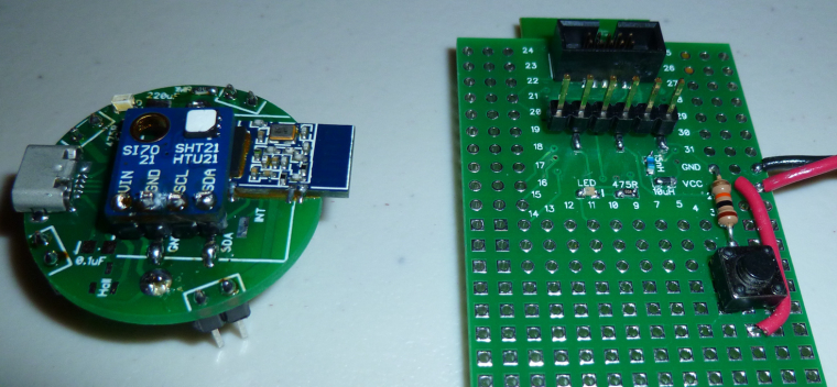
For the nRF52832 (on the right), I literally used a button push to simulate a leak detection. However, for the nRF51822 (on the left), I did use the leak detection pins. I've tried putting it on a flooded surface and, indeed, it does detect water. By that I mean a water leak is enough to wake it up from sleep and trigger a detection event. -
I just now measured the sleep current on the nRF51822 (above), and it is 3.9ua. So, higher than the nRF52822. Go figure.
BTW, I'm using a uCurrent Gold paired to a Fluke 87V for my current measurements, so I think my measurements are probably reasonably accurate (and repeatable by anyone else with similar equipment).
-
@NeverDie Nice stuff! Perhaps you could file a PR and include it as a example in the repo?
@Anticimex said in nRF5 Bluetooth action!:
@NeverDie Nice stuff! Perhaps you could file a PR and include it as a example in the repo?
I think instead of that I'll bake it into an improved demo script for the multisensor node and post it there. So, instead of waking up every 5 seconds to blink an LED, it will instead wake-up every 5 minutes to take a temperature/humidity reading and report it back wirelessly to the gateway. Meanwhile, if it happens to detect a water leak, it will report that the instant it is detected. That will be the practical upshot of the above script, which is a boilerplate for how to quickly respond to interrupts while sleeping and yet still remain miserly with respect to battery consumption.
Or, better yet, I'll do it for the PIR demo code, since it doesn't yet have demo code. Same basic idea.
-
@NeverDie Nice stuff! Perhaps you could file a PR and include it as a example in the repo?
@Anticimex said in nRF5 Bluetooth action!:
@NeverDie Nice stuff! Perhaps you could file a PR and include it as a example in the repo?
I posted an enhanced version of it here as the demo sketch--it includes proper MySensors radio code as well: https://www.openhardware.io/view/499/10-years-wireless-PIR-Sensor-on-just-one-set-of-3-AAs#tabs-source
-
Need your help, guys. I am trying to reprogram a smart socket based on nrf51 module. The schematic is:
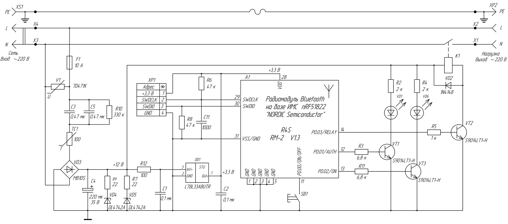
I successfully did it using conventional BT Arduino core (Sandeep's) and I was able to switch the relay on/off.
However, when I tried to use Mysensors ESB5 implementation, the relay just switches On briefly and then immediately Off.
I believe this is because the pin doesn't supply enough current for the transistor to saturate (3.3v/1k=3.3ma).
Questions:
a ) shall I use hwPinMode(PIN, OUTPUT_S0H1)? if yes,
b ) why in non-MySensors sketch a simple pinMode(PIN, OUTPUT) worked?
Does MuSensors implementation overrides Sandeep's definitions so the pin supplies less current? -
Need your help, guys. I am trying to reprogram a smart socket based on nrf51 module. The schematic is:
I successfully did it using conventional BT Arduino core (Sandeep's) and I was able to switch the relay on/off.
However, when I tried to use Mysensors ESB5 implementation, the relay just switches On briefly and then immediately Off.
I believe this is because the pin doesn't supply enough current for the transistor to saturate (3.3v/1k=3.3ma).
Questions:
a ) shall I use hwPinMode(PIN, OUTPUT_S0H1)? if yes,
b ) why in non-MySensors sketch a simple pinMode(PIN, OUTPUT) worked?
Does MuSensors implementation overrides Sandeep's definitions so the pin supplies less current?@Toyman I don't know the answers, but section 20.4.1 GPIO Electrical Specification from the datasheet might give you some insight. What I notice from it is that there's quite a spread between the min and max driver current rating, with no real explanation as to why. So, for that reason, if your target currents are higher than the minimum ratings, perhaps you're better off using an nRF5 pin to control a load switch, which in turn should easily handle your desired currents?