RFM69CW Gateway and Nodes are not working with Api newer then 2.0.0
-
It is grey, uploads it and same thing as before.
Sensor cant get the gateway, gateway stops at "pm open,type:2 0".Don't know where the problem is :/
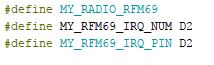
@Floca seems like MY_RF69_IRQ_NUM is important. If I do this
//#define MY_RF69_IRQ_NUM MY_RF69_IRQ_PINmy gateway stops at
0;255;3;0;9;6624 MCO:BGN:STP
0;255;3;0;9;6675 MCO:BGN:INIT OK,TSP=1
pm open,type:2 0
and never receives any messages. I even had to restart the node after a flashed the gateway with IRQ_NUM defined. Before I restarted the node it wasn't able to get the transport up and running again, showing repeated !TSF:SND:TNR.
-
seems that this is the problem...
When it is gray, the define is not found, am i right?What would you think? Arduino IDE reinstalling or what could be the problem?
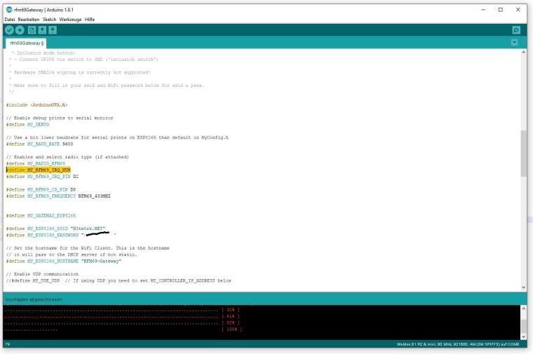
@Floca gray or not is just syntax highliting. It does not affect the compiled code. This is what mine looks like:

But what you did before, with setting both to D2, should work. Could you try that again, and reset the temperature node after you have uploaded the new sketch to the gateway?
-
Ok, i delete the eeprom from both, gateway and node and flash the old scripts with additional definiton of Num IRQ for the gateway?
-
I have No Reply, don't know what i do wrong :(
/** * The MySensors Arduino library handles the wireless radio link and protocol * between your home built sensors/actuators and HA controller of choice. * The sensors forms a self healing radio network with optional repeaters. Each * repeater and gateway builds a routing tables in EEPROM which keeps track of the * network topology allowing messages to be routed to nodes. * * Created by Henrik Ekblad <henrik.ekblad@mysensors.org> * Copyright (C) 2013-2015 Sensnology AB * Full contributor list: https://github.com/mysensors/Arduino/graphs/contributors * * Documentation: http://www.mysensors.org * Support Forum: http://forum.mysensors.org * * This program is free software; you can redistribute it and/or * modify it under the terms of the GNU General Public License * version 2 as published by the Free Software Foundation. * ******************************* * * REVISION HISTORY * Version 1.0 - Henrik EKblad * Contribution by tekka, * Contribution by a-lurker and Anticimex, * Contribution by Norbert Truchsess <norbert.truchsess@t-online.de> * Contribution by Ivo Pullens (ESP8266 support) * * DESCRIPTION * The EthernetGateway sends data received from sensors to the WiFi link. * The gateway also accepts input on ethernet interface, which is then sent out to the radio network. * * VERA CONFIGURATION: * Enter "ip-number:port" in the ip-field of the Arduino GW device. This will temporarily override any serial configuration for the Vera plugin. * E.g. If you want to use the defualt values in this sketch enter: 192.168.178.66:5003 * * LED purposes: * - To use the feature, uncomment WITH_LEDS_BLINKING in MyConfig.h * - RX (green) - blink fast on radio message recieved. In inclusion mode will blink fast only on presentation recieved * - TX (yellow) - blink fast on radio message transmitted. In inclusion mode will blink slowly * - ERR (red) - fast blink on error during transmission error or recieve crc error * * See http://www.mysensors.org/build/esp8266_gateway for wiring instructions. * nRF24L01+ ESP8266 * VCC VCC * CE GPIO4 * CSN/CS GPIO15 * SCK GPIO14 * MISO GPIO12 * MOSI GPIO13 * GND GND * * Not all ESP8266 modules have all pins available on their external interface. * This code has been tested on an ESP-12 module. * The ESP8266 requires a certain pin configuration to download code, and another one to run code: * - Connect REST (reset) via 10K pullup resistor to VCC, and via switch to GND ('reset switch') * - Connect GPIO15 via 10K pulldown resistor to GND * - Connect CH_PD via 10K resistor to VCC * - Connect GPIO2 via 10K resistor to VCC * - Connect GPIO0 via 10K resistor to VCC, and via switch to GND ('bootload switch') * * Inclusion mode button: * - Connect GPIO5 via switch to GND ('inclusion switch') * * Hardware SHA204 signing is currently not supported! * * Make sure to fill in your ssid and WiFi password below for ssid & pass. */ #include <ArduinoOTA.h> // Enable debug prints to serial monitor #define MY_DEBUG // Use a bit lower baudrate for serial prints on ESP8266 than default in MyConfig.h #define MY_BAUD_RATE 9600 // Enables and select radio type (if attached) #define MY_RADIO_RFM69 #define MY_RFM69_IRQ_NUM D2 #define MY_RFM69_IRQ_PIN D2 #define MY_RFM69_CS_PIN D8 #define MY_RFM69_FREQUENCY RFM69_433MHZ #define MY_GATEWAY_ESP8266 #define MY_ESP8266_SSID "N3tw0rk.NET" #define MY_ESP8266_PASSWORD "123456" // Set the hostname for the WiFi Client. This is the hostname // it will pass to the DHCP server if not static. #define MY_ESP8266_HOSTNAME "RFM69-Gateway" // Enable UDP communication //#define MY_USE_UDP // If using UDP you need to set MY_CONTROLLER_IP_ADDRESS below // Enable MY_IP_ADDRESS here if you want a static ip address (no DHCP) //#define MY_IP_ADDRESS 192,168,178,87 // If using static ip you can define Gateway and Subnet address as well //#define MY_IP_GATEWAY_ADDRESS 192,168,178,1 //#define MY_IP_SUBNET_ADDRESS 255,255,255,0 // The port to keep open on node server mode #define MY_PORT 5003 // How many clients should be able to connect to this gateway (default 1) #define MY_GATEWAY_MAX_CLIENTS 2 // Controller ip address. Enables client mode (default is "server" mode). // Also enable this if MY_USE_UDP is used and you want sensor data sent somewhere. //#define MY_CONTROLLER_IP_ADDRESS 192, 168, 178, 68 // Enable inclusion mode #define MY_INCLUSION_MODE_FEATURE // Enable Inclusion mode button on gateway // #define MY_INCLUSION_BUTTON_FEATURE // Set inclusion mode duration (in seconds) #define MY_INCLUSION_MODE_DURATION 60 // Digital pin used for inclusion mode button //#define MY_INCLUSION_MODE_BUTTON_PIN 3 // Set blinking period // #define MY_DEFAULT_LED_BLINK_PERIOD 300 // Flash leds on rx/tx/err // Led pins used if blinking feature is enabled above //#define MY_DEFAULT_ERR_LED_PIN 16 // Error led pin //#define MY_DEFAULT_RX_LED_PIN 16 // Receive led pin //#define MY_DEFAULT_TX_LED_PIN 16 // the PCB, on board LED #if defined(MY_USE_UDP) #include <WiFiUDP.h> #else #include <ESP8266WiFi.h> #endif #include <MySensors.h> void setup() { // Setup locally attached sensors ArduinoOTA.onStart([]() { debug("ArduinoOTA start\n"); }); ArduinoOTA.onEnd([]() { debug("\nArduinoOTA end\n"); }); ArduinoOTA.setPassword((const char *)"123"); ArduinoOTA.onProgress([](unsigned int progress, unsigned int total) { debug("OTA Progress: %u%%\r", (progress / (total / 100))); }); ArduinoOTA.onError([](ota_error_t error) { debug("Error[%u]: ", error); if (error == OTA_AUTH_ERROR) { debug("Auth Failed\n"); } else if (error == OTA_BEGIN_ERROR) { debug("Begin Failed\n"); } else if (error == OTA_CONNECT_ERROR) { debug("Connect Failed\n"); } else if (error == OTA_RECEIVE_ERROR) { debug("Receive Failed\n"); } else if (error == OTA_END_ERROR) { debug("End Failed\n"); } }); ArduinoOTA.begin(); } void presentation() { // Present locally attached sensors here } void loop() { // Send locally attech sensors data here ArduinoOTA.handle(); } -
@mfalkvidd That would be great!
Your test Module for the Gateway was an Wemos, an NodeMcu or something else?
regards
Hello! It looks like you're interested in this conversation, but you don't have an account yet.
Getting fed up of having to scroll through the same posts each visit? When you register for an account, you'll always come back to exactly where you were before, and choose to be notified of new replies (either via email, or push notification). You'll also be able to save bookmarks and upvote posts to show your appreciation to other community members.
With your input, this post could be even better 💗
Register Login