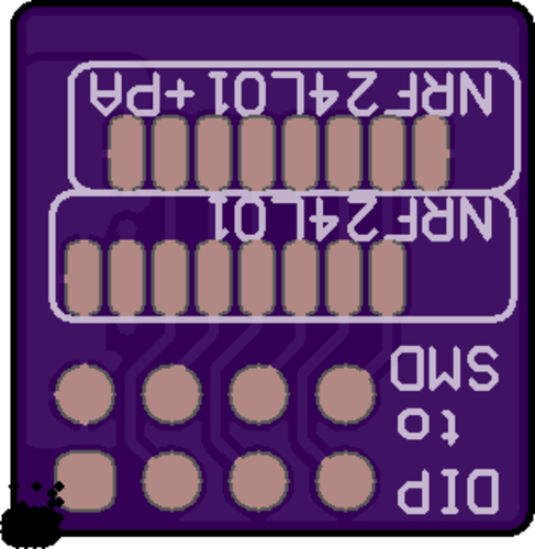
💬 DIP to SMD NRF24L01 adapter
-
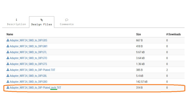
I tried uploading a zip of your design files to OSH Park, but OSH Park says that there's no drill file among them. Is there?
-
There seems to be a fault in those drilling instructions though. Here's what the board looks like if I upload the files to OSH Park:
@NeverDie said in 💬 DIP to SMD NRF24L01 adapter:
There seems to be a fault in those drilling instructions though.
Yes, I see. The problem is that I released the gerber files in the metric system. Now I have released a new drill file. You can try again.
-
@NeverDie said in 💬 DIP to SMD NRF24L01 adapter:
There seems to be a fault in those drilling instructions though.
Yes, I see. The problem is that I released the gerber files in the metric system. Now I have released a new drill file. You can try again.
-
Thanks very much for posting this board. I've ordered 9 of them.
One small suggestion: if you could center the 8 pin connector, it would be better from my point of view. For instance, it might center a little better on my 8-pin adapter shield:
https://www.openhardware.io/view/438/nRF24L01-Pro-Mini-Shield -
Thanks very much for posting this board. I've ordered 9 of them.
One small suggestion: if you could center the 8 pin connector, it would be better from my point of view. For instance, it might center a little better on my 8-pin adapter shield:
https://www.openhardware.io/view/438/nRF24L01-Pro-Mini-Shield@NeverDie said in 💬 DIP to SMD NRF24L01 adapter:
if you could center the 8 pin connector, it would be better from my point of view.
OK. I'll do it in my next revision of this adapter.
-
Hi, thanks for designing an adapter that includes both the "normal" and the PA+LNA versions of the SMD NRF24L01+. Any reason why you don't include any decoupling capacitors? Typically, a 100nF and a 4.7 to 47µF capacitors between VCC and GND are recommended...
I'm using emc2cube's adapters (https://www.openhardware.io/view/297/SMDnRF24_adapter, https://github.com/emc2cube/SMDnRF24_adapter/tree/master/PA_LNA) and they are really great, but they are designed only for the "normal" and only for the PA+LNA versions, so your adapter is even better.
Also: Any reason you are "wasting" a lot of space on the board? I suppose you wanted to make the adapter the same width as the DIP nrf24l01+? Since the smd versions are smaller, you can still align one edge with the original size, align the smd nrf24l01 with that edge and make the board smaller on the other side (i.e. align both edges with the SMD nrf24l01+), i.e. align the width of the adapter with the width of the smd modules. emc2cube does this and the adapter feels much more natural than a board that is larger than the smd nrf24l01...
@reinhold said in 💬 DIP to SMD NRF24L01 adapter:
Typically, a 1nF
Did you perhaps mean to write 100nF?
-
@reinhold said in 💬 DIP to SMD NRF24L01 adapter:
Typically, a 1nF
Did you perhaps mean to write 100nF?
-
It seems @kalina is using the 10nF, 1µF + 10µF combo in his designs, so it's not neccessary for him to add them to the adapter. Still, other designs (or manually wired nodes) do not always have the capacitors, so it would be nice to have the pads on the adapter in case one wants to add the capacitors directly with the wireless module.
Hi @reinhold.
@reinhold said in 💬 DIP to SMD NRF24L01 adapter:
Also: Any reason you are "wasting" a lot of space on the board? I suppose you wanted to make the adapter the same width as the DIP nrf24l01+?
Yes, In this case, the size didn't matter :-)
@reinhold said in 💬 DIP to SMD NRF24L01 adapter:
It seems @kalina is using the 10nF, 1µF + 10µF combo in his designs, so it's not neccessary for him to add them to the adapter.
You are absolutely right. In my projects there are all the necessary components for achieving good power. And in this adapter I only traced polygon pours for 3.3V, because in my opinion the radio module should not be powered by narrow conductors.
@reinhold said in 💬 DIP to SMD NRF24L01 adapter:
it would be nice to have the pads on the adapter in case one wants to add the capacitors directly with the wireless module
OK. I will take this into account for the following developments.
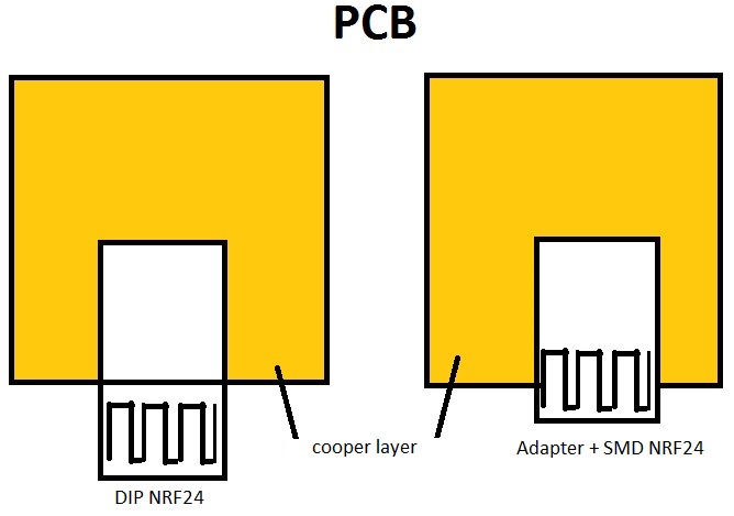
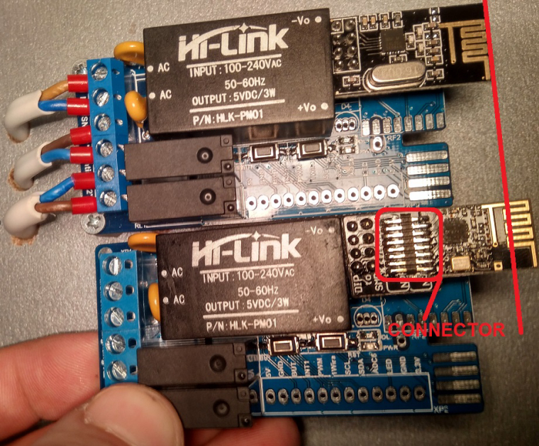
I found one significant drawback of this adapter - it is shorter in length compared to the original radio module (DIP). So if it (adapter+SMD NRF) is soldered into a board, then the antenna will be located directly above the copper layer. Communication in this case will be bad. So, I had to solder the connector between the adapter and the SMD radio module, so that the antenna of the radio has moved beyond the board's dimensions. Please, look at picture below, it will explains better...
-
Hi @reinhold.
@reinhold said in 💬 DIP to SMD NRF24L01 adapter:
Also: Any reason you are "wasting" a lot of space on the board? I suppose you wanted to make the adapter the same width as the DIP nrf24l01+?
Yes, In this case, the size didn't matter :-)
@reinhold said in 💬 DIP to SMD NRF24L01 adapter:
It seems @kalina is using the 10nF, 1µF + 10µF combo in his designs, so it's not neccessary for him to add them to the adapter.
You are absolutely right. In my projects there are all the necessary components for achieving good power. And in this adapter I only traced polygon pours for 3.3V, because in my opinion the radio module should not be powered by narrow conductors.
@reinhold said in 💬 DIP to SMD NRF24L01 adapter:
it would be nice to have the pads on the adapter in case one wants to add the capacitors directly with the wireless module
OK. I will take this into account for the following developments.
I found one significant drawback of this adapter - it is shorter in length compared to the original radio module (DIP). So if it (adapter+SMD NRF) is soldered into a board, then the antenna will be located directly above the copper layer. Communication in this case will be bad. So, I had to solder the connector between the adapter and the SMD radio module, so that the antenna of the radio has moved beyond the board's dimensions. Please, look at picture below, it will explains better...
I have uploaded photo, see above...
Hello! It looks like you're interested in this conversation, but you don't have an account yet.
Getting fed up of having to scroll through the same posts each visit? When you register for an account, you'll always come back to exactly where you were before, and choose to be notified of new replies (either via email, or push notification). You'll also be able to save bookmarks and upvote posts to show your appreciation to other community members.
With your input, this post could be even better 💗
Register Login