Double SPI Radio Raspberry Pi
-
I have connected as an experiment two nrf24l01+ to the raspberry pi (spi enabled), my goal is to change one of the nrf24l01 for a lora or a 433... but since I do not have either yet, two nrf24l01+ it is :-)
I decided to try spi0.1 (with the cs on pin 26) because of the bluetooth/spi1 stuff...
The first radio is wired like on the homepage
The second radio has its MOSI,MISO, SCLK, GND, 3.3v connected on the same wires as the first radio
And the additional wires to
IRQ=pin 16
CE=pin 18
CS=pin 26And 47pF cap between ground and vcc on the radio's (4.7pF does not work even if I wire one radio)
So I have two MySensor folders configures with
./configure --my-transport=nrf24 --my-rf24-ce-pin=18 --my-rf24-cs-pin=26 --my-rf24-irq-pin=16 --spi-spidev-device=/dev/spidev0.1 --spi-driver=SPIDEV --my-port=5004 --my-node-id=15./configure --my-transport=nrf24 --my-rf24-irq-pin=15 --spi-spidev-device=/dev/spidev0.0 --spi-driver=SPIDEVAnyway although the both run and something got transmitted and received... its kinda not working... individually (one 3.3v disconnected or both connected) they work fine communicating with my vento sensor... so the radio's are fine. (and so are the use of the alternative pins)
but when both powered, the original pin radio works but the second radio does not (even with 3.3v/ground on other pins) or visa versa...
when both using mysensors it crashes
Was kinda hoping somebody could shed a light on why...
is it the cs line not being low from the other radio? signal too weak?
interference with packages? ?also tested dtoverlay=spi0-cs,cs0_pin=24,cs1_pin=26 and dtoverlay=spi0-hw-cs in the /boot/config.txt to no avail,
also note with one radio I did not activate the dtparam=spi=on, it still worked...
2x nrf24l01 is one mysensors gateway and one milight, although I have milight in rflink :-)
Some logs...
Controller...
mysgw: MCO:BGN:INIT GW,CP=RNNG--Q-,VER=2.2.0-beta
mysgw: TSF:LRT:OK
mysgw: TSM:INIT
mysgw: TSF:WUR:MS=0
mysgw: TSM:INIT:TSP OK
mysgw: TSM:INIT:GW MODE
mysgw: TSM:READY:ID=0,PAR=0,DIS=0
mysgw: MCO:REG:NOT NEEDED
mysgw: Listening for connections on 0.0.0.0:5003
mysgw: MCO:BGN:STP
mysgw: MCO:BGN:INIT OK,TSP=1
mysgw: TSF:MSG:READ,0-0-0,s=0,c=0,t=0,pt=0,l=0,sg=0:
mysgw: !TSF:MSG:LEN,0!=7
Reset controller...
mysgw: MCO:BGN:INIT GW,CP=RNNG--Q-,VER=2.2.0-beta
mysgw: TSF:LRT:OK
mysgw: TSM:INIT
mysgw: TSF:WUR:MS=0
mysgw: TSM:INIT:TSP OK
mysgw: TSM:INIT:GW MODE
mysgw: TSM:READY:ID=0,PAR=0,DIS=0
mysgw: MCO:REG:NOT NEEDED
mysgw: Listening for connections on 0.0.0.0:5003
mysgw: MCO:BGN:STP
mysgw: MCO:BGN:INIT OK,TSP=1
mysgw: TSF:MSG:READ,15-255-255,s=255,c=7,t=7,pt=0,l=0,sg=0:
mysgw: TSF:MSG:BC
mysgw: TSF:MSG:READ,0-0-14,s=14,c=6,t=0,pt=0,l=0,sg=0:
mysgw: !TSF:MSG:LEN,14!=7
mysgw: TSF:MSG:READ,0-0-14,s=14,c=6,t=0,pt=0,l=0,sg=0:
mysgw: !TSF:MSG:LEN,0!=7
mysgw: TSF:MSG:READ,255-62-2,s=255,c=7,t=255,pt=0,l=0,sg=0:
mysgw: !TSF:MSG:PVER,3!=2
Node 15
mysgw: MCO:BGN:INIT NODE,CP=RNNN--Q-,VER=2.2.0-beta mysgw: TSM:INIT mysgw: TSF:WUR:MS=0 mysgw: TSM:INIT:TSP OK mysgw: TSM:INIT:STATID=15 mysgw: TSF:SID:OK,ID=15 mysgw: TSM:FPAR mysgw: TSF:MSG:SEND,15-15-255-255,s=255,c=3,t=7,pt=0,l=0,sg=0,ft=0,st=OK: mysgw: !TSM:FPAR:NO REPLY mysgw: TSM:FPAR mysgw: TSF:MSG:SEND,15-15-255-255,s=255,c=3,t=7,pt=0,l=0,sg=0,ft=0,st=OK: mysgw: !TSM:FPAR:NO REPLY mysgw: TSM:FPAR mysgw: TSF:MSG:SEND,15-15-255-255,s=255,c=3,t=7,pt=0,l=0,sg=0,ft=0,st=OK: mysgw: !TSM:FPAR:NO REPLY mysgw: TSM:FPAR mysgw: TSF:MSG:SEND,15-15-255-255,s=255,c=3,t=7,pt=0,l=0,sg=0,ft=0,st=OK: mysgw: !TSM:FPAR:FAIL mysgw: TSM:FAIL:CNT=1 mysgw: TSM:FAIL:DIS mysgw: TSF:TDI:TSL mysgw: TSM:FAIL:RE-INIT mysgw: TSM:INIT mysgw: TSM:INIT:TSP OK mysgw: TSM:INIT:STATID=15 mysgw: TSF:SID:OK,ID=15 mysgw: TSM:FPAR <reset controller> mysgw: TSF:MSG:SEND,15-15-255-255,s=255,c=3,t=7,pt=0,l=0,sg=0,ft=0,st=OK: mysgw: TSF:MSG:READ,15-15-255,s=255,c=3,t=7,pt=0,l=0,sg=0: mysgw: TSF:MSG:BC mysgw: !TSM:FPAR:NO REPLY mysgw: TSM:FPAR -
I have connected as an experiment two nrf24l01+ to the raspberry pi (spi enabled), my goal is to change one of the nrf24l01 for a lora or a 433... but since I do not have either yet, two nrf24l01+ it is :-)
I decided to try spi0.1 (with the cs on pin 26) because of the bluetooth/spi1 stuff...
The first radio is wired like on the homepage
The second radio has its MOSI,MISO, SCLK, GND, 3.3v connected on the same wires as the first radio
And the additional wires to
IRQ=pin 16
CE=pin 18
CS=pin 26And 47pF cap between ground and vcc on the radio's (4.7pF does not work even if I wire one radio)
So I have two MySensor folders configures with
./configure --my-transport=nrf24 --my-rf24-ce-pin=18 --my-rf24-cs-pin=26 --my-rf24-irq-pin=16 --spi-spidev-device=/dev/spidev0.1 --spi-driver=SPIDEV --my-port=5004 --my-node-id=15./configure --my-transport=nrf24 --my-rf24-irq-pin=15 --spi-spidev-device=/dev/spidev0.0 --spi-driver=SPIDEVAnyway although the both run and something got transmitted and received... its kinda not working... individually (one 3.3v disconnected or both connected) they work fine communicating with my vento sensor... so the radio's are fine. (and so are the use of the alternative pins)
but when both powered, the original pin radio works but the second radio does not (even with 3.3v/ground on other pins) or visa versa...
when both using mysensors it crashes
Was kinda hoping somebody could shed a light on why...
is it the cs line not being low from the other radio? signal too weak?
interference with packages? ?also tested dtoverlay=spi0-cs,cs0_pin=24,cs1_pin=26 and dtoverlay=spi0-hw-cs in the /boot/config.txt to no avail,
also note with one radio I did not activate the dtparam=spi=on, it still worked...
2x nrf24l01 is one mysensors gateway and one milight, although I have milight in rflink :-)
Some logs...
Controller...
mysgw: MCO:BGN:INIT GW,CP=RNNG--Q-,VER=2.2.0-beta
mysgw: TSF:LRT:OK
mysgw: TSM:INIT
mysgw: TSF:WUR:MS=0
mysgw: TSM:INIT:TSP OK
mysgw: TSM:INIT:GW MODE
mysgw: TSM:READY:ID=0,PAR=0,DIS=0
mysgw: MCO:REG:NOT NEEDED
mysgw: Listening for connections on 0.0.0.0:5003
mysgw: MCO:BGN:STP
mysgw: MCO:BGN:INIT OK,TSP=1
mysgw: TSF:MSG:READ,0-0-0,s=0,c=0,t=0,pt=0,l=0,sg=0:
mysgw: !TSF:MSG:LEN,0!=7
Reset controller...
mysgw: MCO:BGN:INIT GW,CP=RNNG--Q-,VER=2.2.0-beta
mysgw: TSF:LRT:OK
mysgw: TSM:INIT
mysgw: TSF:WUR:MS=0
mysgw: TSM:INIT:TSP OK
mysgw: TSM:INIT:GW MODE
mysgw: TSM:READY:ID=0,PAR=0,DIS=0
mysgw: MCO:REG:NOT NEEDED
mysgw: Listening for connections on 0.0.0.0:5003
mysgw: MCO:BGN:STP
mysgw: MCO:BGN:INIT OK,TSP=1
mysgw: TSF:MSG:READ,15-255-255,s=255,c=7,t=7,pt=0,l=0,sg=0:
mysgw: TSF:MSG:BC
mysgw: TSF:MSG:READ,0-0-14,s=14,c=6,t=0,pt=0,l=0,sg=0:
mysgw: !TSF:MSG:LEN,14!=7
mysgw: TSF:MSG:READ,0-0-14,s=14,c=6,t=0,pt=0,l=0,sg=0:
mysgw: !TSF:MSG:LEN,0!=7
mysgw: TSF:MSG:READ,255-62-2,s=255,c=7,t=255,pt=0,l=0,sg=0:
mysgw: !TSF:MSG:PVER,3!=2
Node 15
mysgw: MCO:BGN:INIT NODE,CP=RNNN--Q-,VER=2.2.0-beta mysgw: TSM:INIT mysgw: TSF:WUR:MS=0 mysgw: TSM:INIT:TSP OK mysgw: TSM:INIT:STATID=15 mysgw: TSF:SID:OK,ID=15 mysgw: TSM:FPAR mysgw: TSF:MSG:SEND,15-15-255-255,s=255,c=3,t=7,pt=0,l=0,sg=0,ft=0,st=OK: mysgw: !TSM:FPAR:NO REPLY mysgw: TSM:FPAR mysgw: TSF:MSG:SEND,15-15-255-255,s=255,c=3,t=7,pt=0,l=0,sg=0,ft=0,st=OK: mysgw: !TSM:FPAR:NO REPLY mysgw: TSM:FPAR mysgw: TSF:MSG:SEND,15-15-255-255,s=255,c=3,t=7,pt=0,l=0,sg=0,ft=0,st=OK: mysgw: !TSM:FPAR:NO REPLY mysgw: TSM:FPAR mysgw: TSF:MSG:SEND,15-15-255-255,s=255,c=3,t=7,pt=0,l=0,sg=0,ft=0,st=OK: mysgw: !TSM:FPAR:FAIL mysgw: TSM:FAIL:CNT=1 mysgw: TSM:FAIL:DIS mysgw: TSF:TDI:TSL mysgw: TSM:FAIL:RE-INIT mysgw: TSM:INIT mysgw: TSM:INIT:TSP OK mysgw: TSM:INIT:STATID=15 mysgw: TSF:SID:OK,ID=15 mysgw: TSM:FPAR <reset controller> mysgw: TSF:MSG:SEND,15-15-255-255,s=255,c=3,t=7,pt=0,l=0,sg=0,ft=0,st=OK: mysgw: TSF:MSG:READ,15-15-255,s=255,c=3,t=7,pt=0,l=0,sg=0: mysgw: TSF:MSG:BC mysgw: !TSM:FPAR:NO REPLY mysgw: TSM:FPAR@TriXwooD Update:
Two radio's (or alternative pins for one radio :-))
for the nrf24l01For Raspberry Pi with 40 pins header (pi zero, pi 3,..)
Note on post above: I tried spi1.0 instead of spi0.0 and spi0.1 and it works... (cs lines not interfering?)
Still not sure why did spi0.0 and spi0.1 not work... what did I wrong there? It should be possible to share the mosi/miso/sclk/gnd/3.3v pins... (maybe it is the cs? or ce?... anyway)This probably means rfm69 wired correctly and a nrf24l01 will work both at the same time on a pi ;-)
Can I compile one gateway with both rfm69 and rf24 enabled at the same time, thus not running two gateways?
For now two gateways running on a pi zero (pi3 with bluetooth not yet tested)
Step Zero
Enable spi1 in /boot/config.txtsudo nano /boot/config.txtdtparam=spi=on dtoverlay=spi1-1cs,cs0_pin=36First Radio Pin
Same as Building a Raspberry Pi Gateway page (with irq pin 15!)First Radio Configure
With irq pin 15!cd MySensorsConfiguring...
./configure --my-transport=nrf24 --my-rf24-irq-pin=15 --spi-spidev-device=/dev/spidev0.0 --spi-driver=SPIDEV --my-port=5003 makeRunning...
cd bin sudo ./mysgw -dSecond Radio Pin
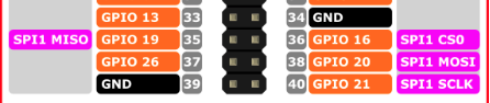
pin 01 3.3v
pin 33 for irq
pin 35 miso
pin 36 cs
pin 37 ce
pin 38 mosi
pin 39 gnd
pin 40 sclkSecond Radio Configure
(in another terminal)A copy of the source
cp -r MySensors MySensorsSecond cd MySensorsSecondConfiguring...
Note the port is 5004 instead of 5003, you can not run two gateways on the same port./configure --my-transport=nrf24 --my-rf24-irq-pin=33 --my-rf24-ce-pin=37 --my-rf24-cs-pin=36 --spi-spidev-device=/dev/spidev1.0 --spi-driver=SPIDEV --my-port=5004 makeRunning...
cd bin sudo ./mysgw -dit works... Fin!
currently running openmilight on radio 1 and mysensors on radio 2 ;-)
-
@TriXwooD Update:
Two radio's (or alternative pins for one radio :-))
for the nrf24l01For Raspberry Pi with 40 pins header (pi zero, pi 3,..)
Note on post above: I tried spi1.0 instead of spi0.0 and spi0.1 and it works... (cs lines not interfering?)
Still not sure why did spi0.0 and spi0.1 not work... what did I wrong there? It should be possible to share the mosi/miso/sclk/gnd/3.3v pins... (maybe it is the cs? or ce?... anyway)This probably means rfm69 wired correctly and a nrf24l01 will work both at the same time on a pi ;-)
Can I compile one gateway with both rfm69 and rf24 enabled at the same time, thus not running two gateways?
For now two gateways running on a pi zero (pi3 with bluetooth not yet tested)
Step Zero
Enable spi1 in /boot/config.txtsudo nano /boot/config.txtdtparam=spi=on dtoverlay=spi1-1cs,cs0_pin=36First Radio Pin
Same as Building a Raspberry Pi Gateway page (with irq pin 15!)First Radio Configure
With irq pin 15!cd MySensorsConfiguring...
./configure --my-transport=nrf24 --my-rf24-irq-pin=15 --spi-spidev-device=/dev/spidev0.0 --spi-driver=SPIDEV --my-port=5003 makeRunning...
cd bin sudo ./mysgw -dSecond Radio Pin
pin 01 3.3v
pin 33 for irq
pin 35 miso
pin 36 cs
pin 37 ce
pin 38 mosi
pin 39 gnd
pin 40 sclkSecond Radio Configure
(in another terminal)A copy of the source
cp -r MySensors MySensorsSecond cd MySensorsSecondConfiguring...
Note the port is 5004 instead of 5003, you can not run two gateways on the same port./configure --my-transport=nrf24 --my-rf24-irq-pin=33 --my-rf24-ce-pin=37 --my-rf24-cs-pin=36 --spi-spidev-device=/dev/spidev1.0 --spi-driver=SPIDEV --my-port=5004 makeRunning...
cd bin sudo ./mysgw -dit works... Fin!
currently running openmilight on radio 1 and mysensors on radio 2 ;-)
@TriXwooD said in Double SPI Radio Raspberry Pi:
dtparam=spi=on
dtoverlay=spi1-1cs,cs0_pin=36@TriXwooD : Thank you, this helped me a lot. I had to use a different pin number in /boot/cmdline.txt though for that it matches the pin number given in the configure statement:
dtparam=spi=on
dtoverlay=spi1-1cs,cs0_pin=16
./configure --my-rf24-cs-pin=36 ...Configure wants the BCM pin number (36), but the dtoverlay wants the corresponding GPIO pin number (16).
Hello! It looks like you're interested in this conversation, but you don't have an account yet.
Getting fed up of having to scroll through the same posts each visit? When you register for an account, you'll always come back to exactly where you were before, and choose to be notified of new replies (either via email, or push notification). You'll also be able to save bookmarks and upvote posts to show your appreciation to other community members.
With your input, this post could be even better 💗
Register Login