$8 Lamp (Outlet) "Smart Plug" Module
-
There is a scetch in mysensors lib doing this. Relayaccuatorwithbutton or something. Download the examplescetches and have a look: http://www.mysensors.org/build/relay#relaywithbuttonactuator-example @Mohsin-Hassan
-
@petewill @Moshe-Livne . Coil activates when i try with a 9v battery, so either bad/cheap relays or to weak power plug. All measures +5v but its not enough. Ill order some new relays.
Controller: Proxmox VM - Home Assistant
MySensors GW: Arduino Uno - W5100 Ethernet, Gw Shield Nrf24l01+ 2,4Ghz
MySensors GW: Arduino Uno - Gw Shield RFM69, 433mhz
RFLink GW - Arduino Mega + RFLink Shield, 433mhz -
@petewill @Moshe-Livne . Coil activates when i try with a 9v battery, so either bad/cheap relays or to weak power plug. All measures +5v but its not enough. Ill order some new relays.
@sundberg84 IMHO 9v will fry the relay. max voltage is 5.5v if my failing memory serves. depends on your relay, naturally but this is the most common one. have a look at the datasheet https://www.ghielectronics.com/downloads/man/20084141716341001RelayX1.pdf
yes it is 5.5v - nominal 5v, max current is 110%. I am sure it can sustain 6 but 9v will be really pushing it IMHO -
It was only to test coil failure and see if it was a power issue :)
Controller: Proxmox VM - Home Assistant
MySensors GW: Arduino Uno - W5100 Ethernet, Gw Shield Nrf24l01+ 2,4Ghz
MySensors GW: Arduino Uno - Gw Shield RFM69, 433mhz
RFLink GW - Arduino Mega + RFLink Shield, 433mhz -
It was only to test coil failure and see if it was a power issue :)
@sundberg84 A self fulfilling prophecy :-)
-
Hi,
any possibility of including a push button to manually trigger the switch on and off as well?
And if possible update Vera on the status change.This way i can make it Wife safe and not get kicked out of the house...
I'm not good with coding but if someone can point me in the right direction please...
@Mohsin-Hassan said:
Hi,
any possibility of including a push button to manually trigger the switch on and off as well?
And if possible update Vera on the status change.This way i can make it Wife safe and not get kicked out of the house...
I'm not good with coding but if someone can point me in the right direction please...
We are discussing this over here: http://forum.mysensors.org/topic/1607/safe-in-wall-ac-to-dc-transformers
You want to be careful you use the right transformer so you don't burn your house down. :) The wife probably wouldn't appreciate that.
I really want to do this too. I'm just waiting for the experts to weigh in on which transformer is safe.
-
@petewill @Moshe-Livne . Coil activates when i try with a 9v battery, so either bad/cheap relays or to weak power plug. All measures +5v but its not enough. Ill order some new relays.
@sundberg84 said:
@petewill @Moshe-Livne . Coil activates when i try with a 9v battery, so either bad/cheap relays or to weak power plug. All measures +5v but its not enough. Ill order some new relays.
So strange that it's not working. What is the power rating of your 5V transformer? Do you have a picture of your set up?
-
I dont reallt wants to admit it...
Well, I ordered the 5v relay from ebay (i have the reciept!) and looking at petewill video it says SRD-05VDC-
Looking at mine it says SRD-12VDC so probalby the sent me a 12v relay...New one will arive soon i hope :) Thank you for the help and sorry for clogging the thread.
Controller: Proxmox VM - Home Assistant
MySensors GW: Arduino Uno - W5100 Ethernet, Gw Shield Nrf24l01+ 2,4Ghz
MySensors GW: Arduino Uno - Gw Shield RFM69, 433mhz
RFLink GW - Arduino Mega + RFLink Shield, 433mhz -
I dont reallt wants to admit it...
Well, I ordered the 5v relay from ebay (i have the reciept!) and looking at petewill video it says SRD-05VDC-
Looking at mine it says SRD-12VDC so probalby the sent me a 12v relay...New one will arive soon i hope :) Thank you for the help and sorry for clogging the thread.
@sundberg84 that makes so much sense! And its not even your fault! :-)
-
I dont reallt wants to admit it...
Well, I ordered the 5v relay from ebay (i have the reciept!) and looking at petewill video it says SRD-05VDC-
Looking at mine it says SRD-12VDC so probalby the sent me a 12v relay...New one will arive soon i hope :) Thank you for the help and sorry for clogging the thread.
-
@sundberg84 said:
Hi @petewill!
I made this :) Great video :+1:I think i get bad reception or something because it works the first 5-6 times and then nothing...
This could also be a power or a wiring issue. But, the antenna is an easy modification so it wouldn't hurt to try this first. Another test is to move the device closer to your gateway. If it still stops after 5-6 times then it probably isn't communication issues.
In the end you describe an cat5 wire added as antenna because of bad reception.
Do you remove the plastic/shielding so its just copper?
Im afraid to short anything out with a long uncovered antenna if thats the case...No, I left the shielding on the wire. Sorry, I should have specified that.
and if i hear you right its 3,28 inches which should be 33,31200 millimeters on the antenna?
I think 3.28 inches is 83.312 millimeters (at least that's what google says it is).
-
@petewill
Just out of interest: how did You come up with the length for the antenna?
I remember vaguely that You can calculate the length if You know the
used frequency but You connect Your wire to an already existing PCB-Antenna...Christoph
@hyla I actually recently did a separate video on how I do this with a little more explanation. If you're interested it's here:
In summary, I measured the length of the existing antenna on the PCB then added additional wire to get it up to the required length for the 2.4GHz range (4.92 in).
-
Thanx :)
Meanwhile I did some research too. The formula (as You all know :) ) is:
Lambda (m) = c(m/s) / f(1/s) with
c= 299711000 m/s
f= 2.400.000.000 hzwhich comes down to 0.1248795833333333 m or roughly 4.92 in
The 1.64 in that are used on the PCB are actually Lambda/3.Nicely done, Pete :)
C.
-
@petewill
Now i got three working relays thanks to you, so again, great video!
Wanted to thank you and also show my sollution.
I hade some 433mhz cheap (not good working) relays with perfect case i could re-use:
The case had a status-led and a switch i use as well.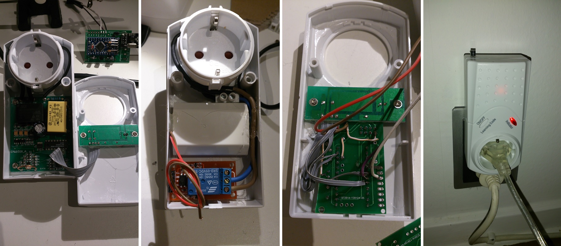
Controller: Proxmox VM - Home Assistant
MySensors GW: Arduino Uno - W5100 Ethernet, Gw Shield Nrf24l01+ 2,4Ghz
MySensors GW: Arduino Uno - Gw Shield RFM69, 433mhz
RFLink GW - Arduino Mega + RFLink Shield, 433mhz -
@petewill
Now i got three working relays thanks to you, so again, great video!
Wanted to thank you and also show my sollution.
I hade some 433mhz cheap (not good working) relays with perfect case i could re-use:
The case had a status-led and a switch i use as well. -
@petewill
Now i got three working relays thanks to you, so again, great video!
Wanted to thank you and also show my sollution.
I hade some 433mhz cheap (not good working) relays with perfect case i could re-use:
The case had a status-led and a switch i use as well.@sundberg84
Nice! That one deserves its own project thread. I think we're many interested in the details. -
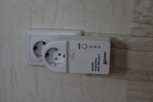
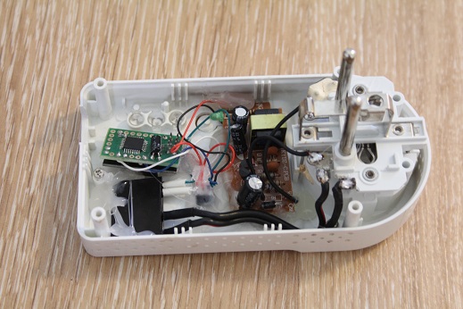
This is may realisation
-
@hyla I actually recently did a separate video on how I do this with a little more explanation. If you're interested it's here:
In summary, I measured the length of the existing antenna on the PCB then added additional wire to get it up to the required length for the 2.4GHz range (4.92 in).
Hi @petewill
I've tried this and had inconclusive results rather then a significant extended rage. Not sure what I'm doing wrong or if it's the quality of my RF module.
I've used some wire (8.33 cm) I had left over but its not one solid copper wire, its has many "strings" inside. In your experiment did you use one solid copper wire and can this influence this hack?
Thanks
-
Hi @petewill
I've tried this and had inconclusive results rather then a significant extended rage. Not sure what I'm doing wrong or if it's the quality of my RF module.
I've used some wire (8.33 cm) I had left over but its not one solid copper wire, its has many "strings" inside. In your experiment did you use one solid copper wire and can this influence this hack?
Thanks
@barduino I am using solid copper cat5e wire. I don't know much about antennas but it may change the behavior. Do you have any old cat5 that you can cut and test with?
My "How To" home automation video channel: https://www.youtube.com/channel/UCq_Evyh5PQALx4m4CQuxqkA
-
@barduino I am using solid copper cat5e wire. I don't know much about antennas but it may change the behavior. Do you have any old cat5 that you can cut and test with?
I'm going to try it.
I'm also using a capacitor on the RF module, not sure if you did combine both techniques.
On a last note, I've noticed some power setting on the MyConfig.h (1.5 lib) cant remember the values form 1.4.1
/**********************************
*  NRF24L01 Driver Defaults
***********************************/
#define RF24_CE_PIN		   9
#define RF24_CS_PIN		   10
#define RF24_PA_LEVEL 	   RF24_PA_MAX
#define RF24_PA_LEVEL_GW   RF24_PA_LOW
So now I'm initializing the gatweway as
// Instanciate MySersors Gateway
MyTransportNRF24 transport(RF24_CE_PIN, RF24_CS_PIN, RF24_PA_LEVEL);
instead of
// Instanciate MySersors Gateway
MyTransportNRF24 transport(RF24_CE_PIN, RF24_CS_PIN, RF24_PA_LEVEL_GW);
Not sure if there is a significant diference here...
The results i'm getting now (after removing the antena, but with capacitor and changes on 1.5 MyConfig) are similar to the results I got from lib 1.4.1 with capacitor. I have a repeater about 15 meters from gateway and if i put it 17 meters it doesnt work anymore (there are some walls on the way)
I'll just add a solid copper antena to see if results change.
Thanks for the info!
Cheers