[contest] Yet another servo blind control project
-
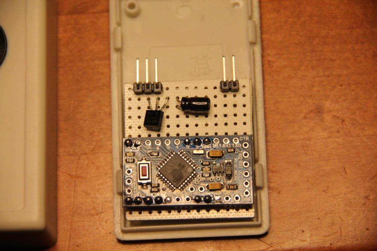
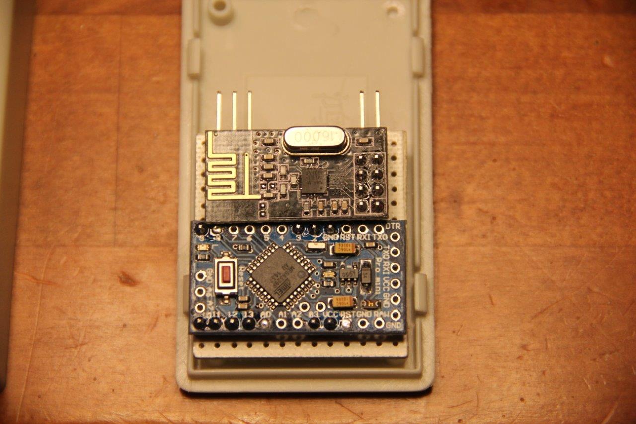
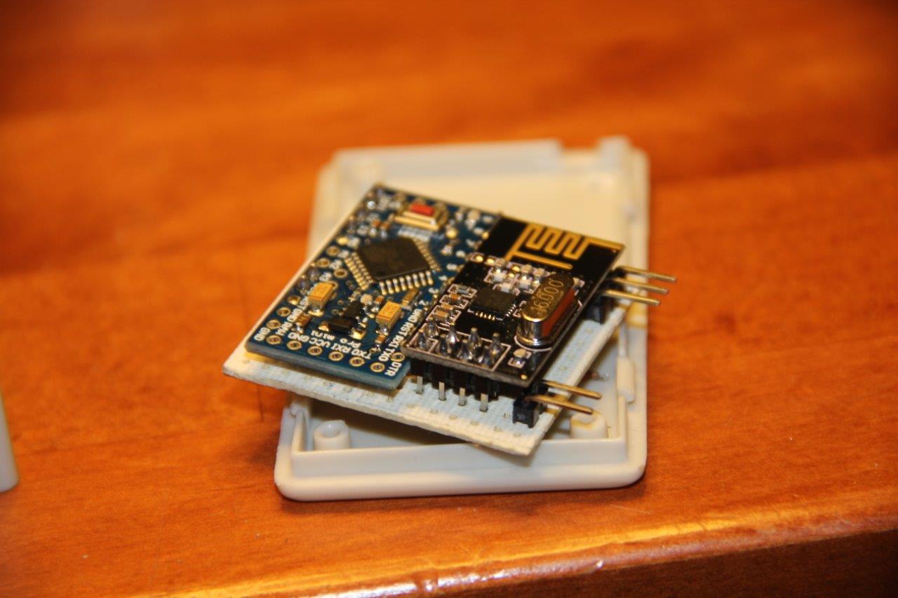
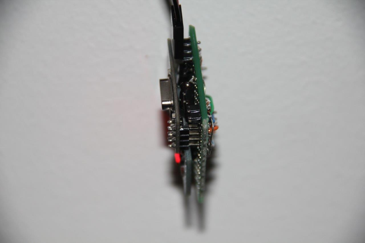
A little bit of progress. Got some functional radios today and I've been trying to fit everything in the control boxes. I think I have an ok design but once I started soldering I realised that the protoboard I was using wasn't dot matrix like it said on the box but copper tracks :rage:
Oh well, I'll have to get something else tomorrow...
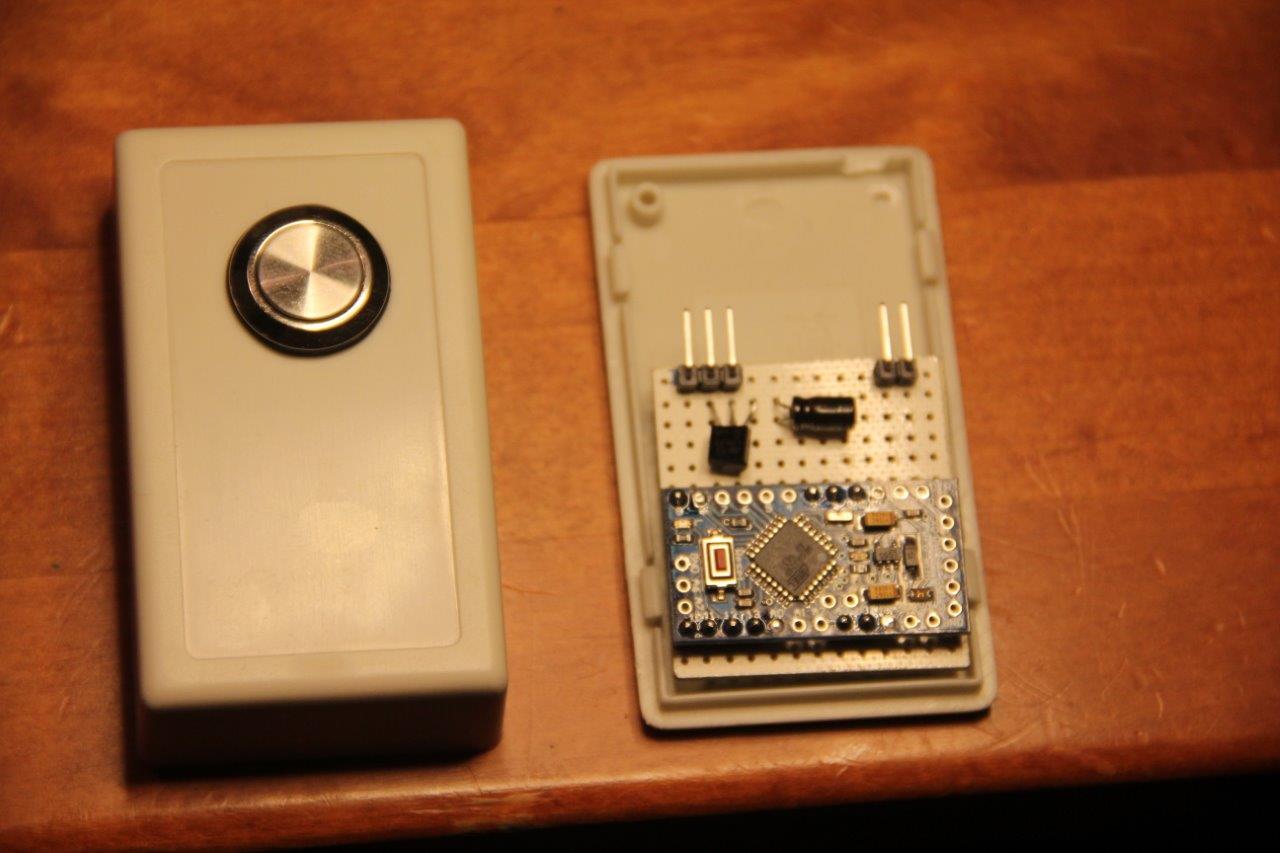
Some mock up pics:
-
First finished sensor!:
Obvious flaw:
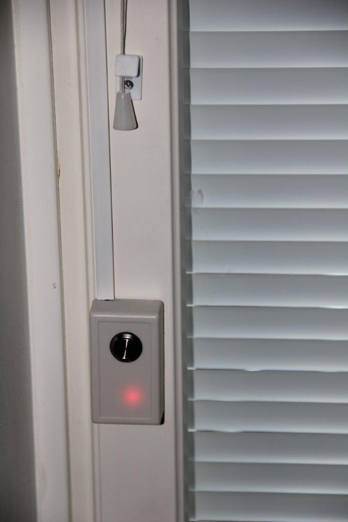
Whole window
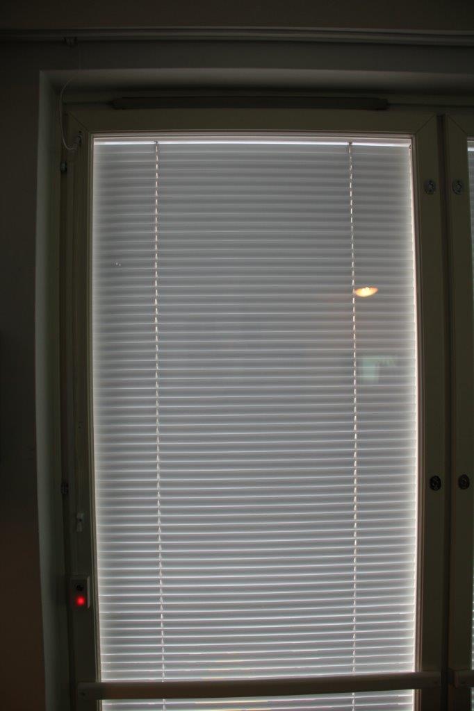
What is the best way to disable the power LED? Desolder it?
-
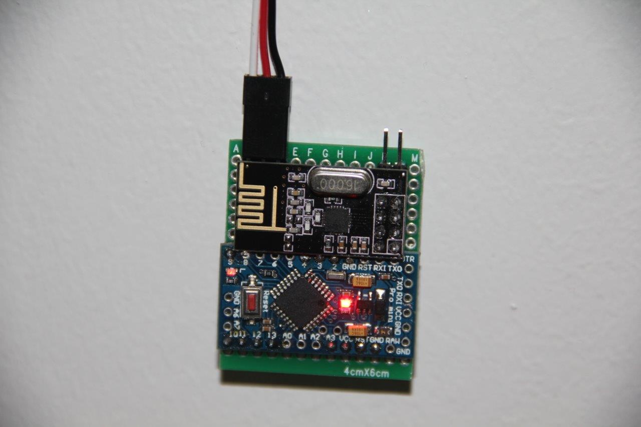
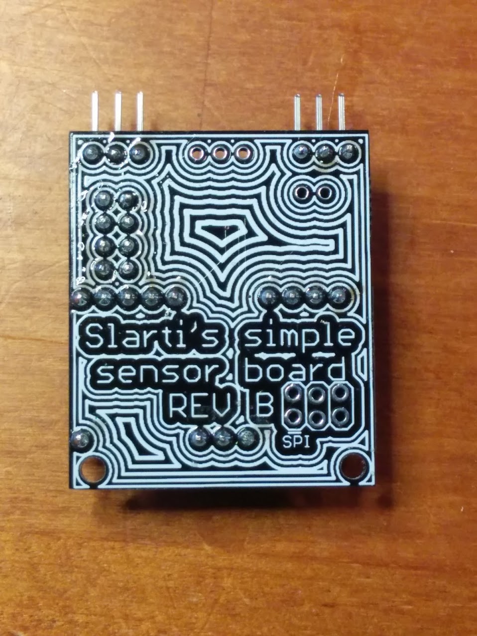
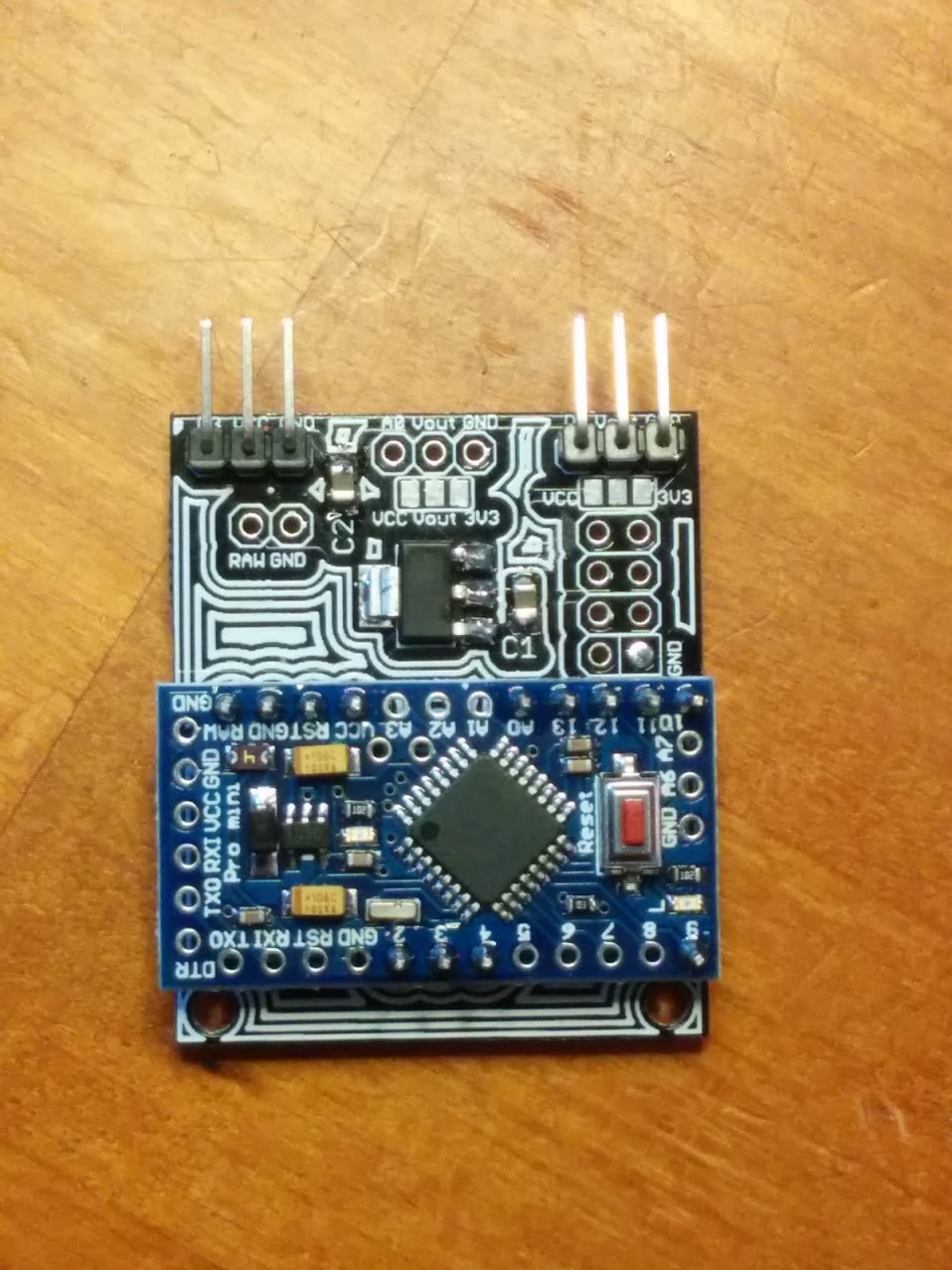
After soldering three ratsnests like the one in the previous post, I decided there has to be a simpler way to do things. So after a day of watching eagle cad tutorials and messing about with the software I came up with a board of my own.
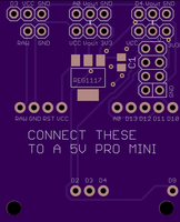
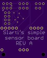
I didn't want to add any stuff I didn't need except for a pin header for raw input, A0-breakout and a choice of 5V/3.3V output for A0 and D4 with a jumper. I also don't want to solder every pin on the pro mini so I can use them possibly elsewhere.
Am I shooting a fly with a cannon? Do I need something else on the board? DirtyPCB and other chinese manufacturers are closed at the moment but are there alternatives besides OSHPARK?
BTW, three arduinos and servos seem to be the maximum simultaneous capacity for the little Nokia charger. They all work but get a bit flaky after a few tests. We'll see what happens when I add the fourth :wink:
-
Ok, I'm calling this one finished. I got all the wiring done and my sketch is working well enough (I'll update the first post). The result doesn't look too bad, either.
I don't know if the little charger doesn't have enough power for the four arduinos and servos at once or if the radio network gets clogged up when Vera tries to control them all at the same time, but they work well as a group when I add a 500ms delay between each command. Here's the lua script I've put in a scene:
local SSID = "urn:upnp-org:serviceId:Dimming1"
local value = luup.variable_get(SSID, "LoadLevelStatus", 59)
windows = {59, 58, 54, 61}
if (value == "0") then
  for i=1,4 do
    luup.call_action(SSID, "SetLoadLevelTarget", {newLoadlevelTarget = "100"}, windows[i])
    luup.sleep(500)
  end
else
  for i=1,4 do
    luup.call_action(SSID, "SetLoadLevelTarget", {newLoadlevelTarget = "0"}, windows[i])
    luup.sleep(500)
  end
end
It just looks up the status of the first window and then changes all positions to the exact opposite of that single window.
I'll update the first post with a video of them being controlled with a zwave fibaro switch that controls another hidden fibaro switch which triggers the lua script in Vera (that's not complicated at all :wink: ).
All in all, this ended up costing almost as much as a commercial solution if you count all the stuff I ordered from ebay and the tools I had to buy. On the other hand I now own the tools and I have a ton of leftover material for several more windows and sensors and now I know some C++, lua and even eagle CAD! Very happy with the end result. Thanks to the MySensors team for making it possible! :+1:
Here's the parts list (price/window):
-
Servo extension cables (2pcs 0.88€)
-
Servos (1pc 2.78€)
-
Bobbins (1pc 0.09€)
-
Buttons (1pc 0.70€)
-
Heat shrink tube (maybe 0.10€ worth)
-
Cat6 cable (solid core) (maybe 0.10€ worth)
-
Protoboard (1pc 0.20€)
-
Project box (1pc 1.44€)
-
Cable raceway (about 1€)
-
3.3V regulators (1pc 0.12€)
-
4,7 uF capacitors (1pc 0.16€)
-
various bits and pieces I can't think of now (can't think of a price, either)
-
5v Arduino Pro Mini clone (1pc 2€)
-
NRF24L01+ -radio (1pc 0.70€)
Grand total/window : 10.27€
-
-
Hi,
Your project is very cool !
Do you known if it is possible to control it with a raspberry pi and domoticz ?
Thank's@exosteph I would think so since these are just MySensors actuator nodes.
The sketches are made using MySensors 1.4 libraries so they might not work with 1.5. I've been really busy lately and haven't had any time for this stuff :cry:
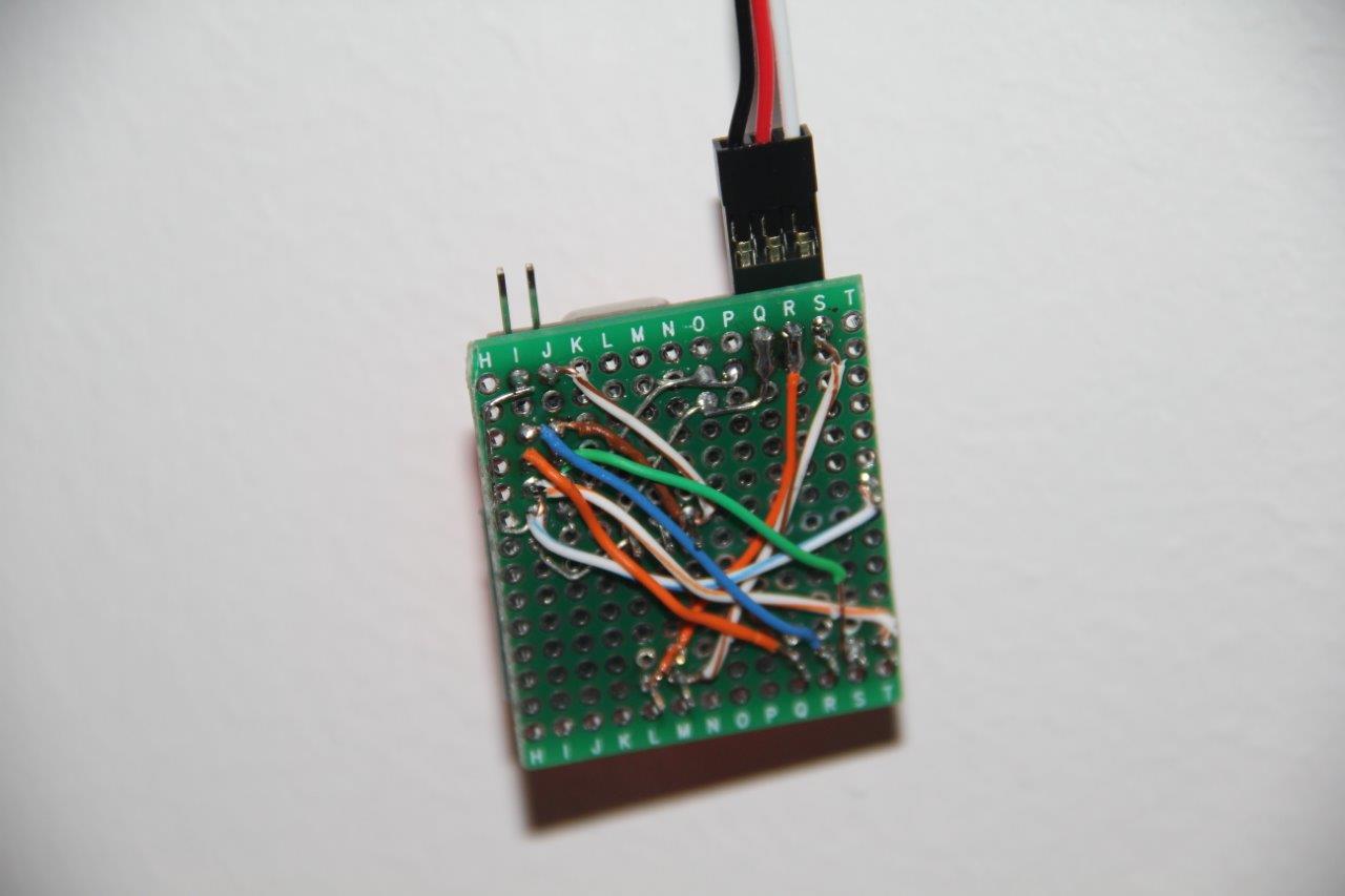
I did make some helper boards earlier to make it easier to solder these sensors (nevermind the horrible soldering)
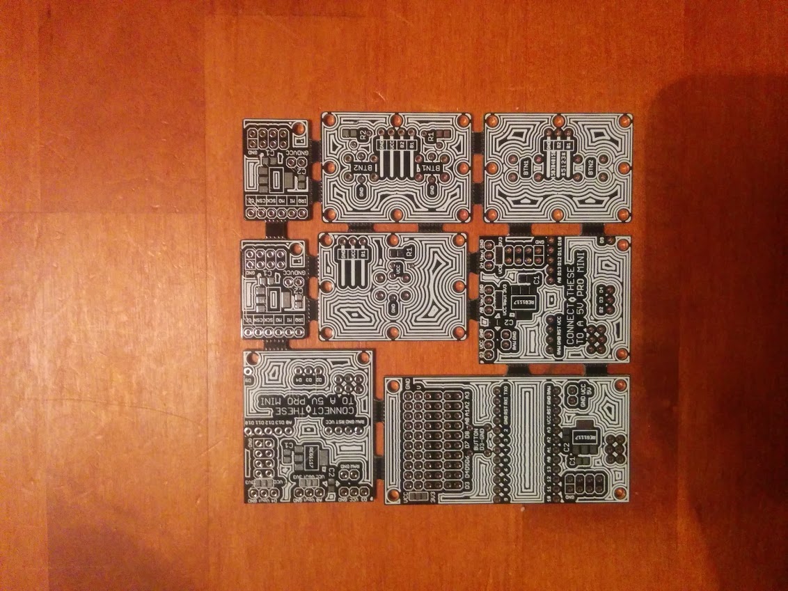
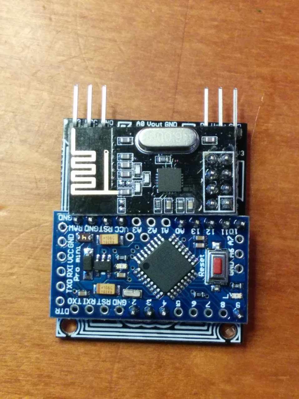
-
Darn. When I connect the servo to the setup the Arduino loses it. Any idea how to tackle this? I've tried various capacitors all over the places:expressionless:
-
It was, in the end and again, a power issue. I didn't mention that I included an RGB control to the node, so I'm feeding the whole nest with a 12v low grade supply. And the servo gets its power via Nano -- no external regulator for that.
All in all, caps in the power supply, radio, nano 5V and 3.3V, aaaallll works now :)
BTW, now that you've had your blinds automated, have you been happy with them? All blinds MySensorised yet?
@Nuubi Yes, I've been happy with them but MySensoring the rest of them is on hold. I've been extremely busy with a new job for a long time and I was supposed to do a few more improvements and tweaks before doing the rest of them. Also, my tinkering space (the kitchen table) is always under heavy pressure from other activities. Maybe I can get some time during the winter.
TL;DR I've been lazy
-
My ethernet gateway died and I made another one on a Raspberry Pi so I updated all of my sensors from 1.4 libraries to 2.2. Here's the updated sketch for these servo blind control nodes:
// A sketch to control a servo with a button and MySensors messages
//#define MY_DEBUG

// Enable and select radio type attached
#define MY_RADIO_NRF24
//#define MY_RADIO_RFM69

#include <SPI.h>
#include <MySensors.h>

#include <Servo.h>
#include <Button.h>        	//https://github.com/JChristensen/Button

#define BUTTON_PIN 4       	//Connect a tactile button switch (or something similar)
                            //from Arduino pin 4 to ground.
#define PULLUP true        	//To keep things simple, we use the Arduino's internal pullup resistor.
#define INVERT true        	//Since the pullup resistor will keep the pin high unless the
                           	//switch is closed, this is negative logic, i.e. a high state
                           	//means the button is NOT pressed. (Assuming a normally open switch.)
#define DEBOUNCE_MS 20     	//A debounce time of 20 milliseconds usually works well for tactile button switches.
#define LONG_PRESS_PERIOD 700   //How long to keep button pressed until sweeping starts

#define MAX_DEGREES 180         //Servo limits. Whatever works for you.
#define MIN_DEGREES 0

#define CHILD_ID 3

Button myBtn(BUTTON_PIN, PULLUP, INVERT, DEBOUNCE_MS);    //Declare the button

Servo myservo;
enum {DECREASING, INCREASING};      //On a servo mounted on the left, with outer slat edge down as closed,
                                    // closing is going toward 180, opening toward 0 (on my fake futaba s3003's)

boolean invertConversions = true;   // false if opening toward 180
boolean servoDirection = INCREASING;     //A variable that keeps the current servo direction
int servoPin = 3;
int servoPosition;
int servoSpeed = 1;                 // The bigger, the faster. 1=slow 5=fast


MyMessage msg(CHILD_ID, V_PERCENTAGE);


void setup(void)
{

}

void presentation()  {
  // Send the sketch version information to the gateway and Controller
  sendSketchInfo("Servo", "1.3");

  // Register all sensors to gw (they will be created as child devices)
  present(CHILD_ID, S_COVER);
}

void loop(void)
{
    myBtn.read();                    		//Read the button

    if (myBtn.wasReleased()){                   //If the button was pressed once sweep to end of current direction
        SweepToDirectionEnd();
        send(msg.set(ConvertDegToPercent(servoPosition)));
    }
    if (myBtn.pressedFor(LONG_PRESS_PERIOD)){   //If the button is held down the servo will start to sweep
        SweepUntilStop();
        send(msg.set(ConvertDegToPercent(servoPosition)));
    }
}


int ConvertPercentToDeg(int percent)
{
    int degree;
    if (invertConversions)
        degree = map(percent, 0, 100, MAX_DEGREES, MIN_DEGREES);
    if (!invertConversions)
        degree = map(percent, 0, 100, MIN_DEGREES, MAX_DEGREES);
    return degree;
}


int ConvertDegToPercent(int degree)
{
    int percent;
    if (invertConversions)
        percent = map(degree, MAX_DEGREES, MIN_DEGREES, 0, 100);
    if (!invertConversions)
        percent = map(degree, MIN_DEGREES, MAX_DEGREES, 0, 100);
    return percent;
}

void receive(const MyMessage &message) {
    myservo.attach(servoPin);
    if (message.type==V_PERCENTAGE) {
        int val = message.getInt();
        SweepToPosition(ConvertPercentToDeg(val)); //In this case the value has to be inverted because 0 = open
        send(msg.set(val));
    }
    else if (message.type==V_STATUS) {
        if (message.getInt() == 1){
        SweepToPosition(ConvertPercentToDeg(100));
        send(msg.set(100));
      }
        else if(message.getInt() == 0) {
        SweepToPosition(ConvertPercentToDeg(0));
        send(msg.set(0));
      }
    }
    else
        myservo.detach();
}


void ServoMoveUp()
{
    if ((myservo.attached()) && servoPosition < MAX_DEGREES){
        servoDirection = INCREASING;
        servoPosition += servoSpeed;
        myservo.write(servoPosition);
        delay(10);
        Serial.print("Servo Position: ");
        Serial.println(servoPosition);
    }
    if (!myservo.attached()){
        Serial.println("Servo stopped while moving toward MAX, direction unchanged");
        delay(100 * servoSpeed);
    }
    if (servoPosition >= MAX_DEGREES){
        Serial.println("MAX reached, changing direction toward MIN");
        servoDirection = DECREASING;
        delay(100 * servoSpeed);			// Wait for the last movement to finish
    }
}


void ServoMoveDown()
{
    if ((myservo.attached()) && servoPosition > MIN_DEGREES){
        servoDirection = DECREASING;
        servoPosition -= servoSpeed;
        delay(10);
        myservo.write(servoPosition);
        Serial.print("Servo Position: ");
        Serial.println(servoPosition);
    }
    if (!myservo.attached()){
        Serial.println("Servo stopped while moving toward MIN, direction unchanged");
        delay(100 * servoSpeed);
    }
    if (servoPosition == MIN_DEGREES){
        Serial.println("MIN reached, changing direction toward MAX");
        servoDirection = INCREASING;
        delay(100 * servoSpeed);
    }
}


void SweepToDirectionEnd()
{
    myservo.attach(servoPin);
    if (servoDirection == INCREASING){
        Serial.println("Going to MAX and stopping there");
        while (servoPosition < MAX_DEGREES){
            ServoMoveUp();
        }
        delay(20 * servoSpeed);
        myservo.detach();
    }
    else if (servoDirection == DECREASING){
        Serial.println("Going to MIN and stopping there");
        while (servoPosition > MIN_DEGREES){
            ServoMoveDown();
        }
        delay(20 * servoSpeed);
        myservo.detach();
    }
}


void SweepUntilStop()
{
    myservo.attach(servoPin);
    while (myBtn.isPressed()){
        myBtn.read();
        if (myBtn.isReleased())
            myservo.detach();
        if (servoDirection == INCREASING)
            ServoMoveUp();
        if (servoDirection == DECREASING)
            ServoMoveDown();
    }
}


void SweepToPosition(int destination)
{
    if (abs(destination - servoPosition) >= servoSpeed)    //Don't move if destination is close to position
        myservo.attach(servoPin);
    if (destination > servoPosition && myservo.attached()){
        Serial.print("Going to ");
        Serial.print(destination);
        Serial.println(" and stopping there");
        while (servoPosition < destination){
            ServoMoveUp();
        }
        delay(20 * servoSpeed);
        myservo.detach();
    }
    if (destination < servoPosition && myservo.attached()){
        Serial.print("Going to ");
        Serial.print(destination);
        Serial.println(" and stopping there");
        while (servoPosition > destination){
            ServoMoveDown();
        }
        delay(20 * servoSpeed);
        myservo.detach();
    }
}```
Hello! It looks like you're interested in this conversation, but you don't have an account yet.
Getting fed up of having to scroll through the same posts each visit? When you register for an account, you'll always come back to exactly where you were before, and choose to be notified of new replies (either via email, or push notification). You'll also be able to save bookmarks and upvote posts to show your appreciation to other community members.
With your input, this post could be even better 💗
Register Login