Solar Powered Mini-Weather Station
-
This is my project!!!!
// Example sketch för a "light switch" where you can control light or something
// else from both vera and a local physical button (connected between digital
// pin 3 and GND).
// This node also works as a repeader for other nodes

#include <MySensor.h>
#include <SPI.h>
#include <DHT.h>

unsigned long SLEEP_TIME = 120000; // Sleep time between reports (in milliseconds)

//pin sensori
#define PIR_PIN 2                   // The digital input you attached your motion sensor.  (Only 2 and 3 generates interrupt!)
#define HUMIDITY_TEMPERATURE_PIN 3  // sensore temperatura umidita
#define RELAY_PIN  4                // relay pin
int BATTERY_SENSE_PIN = A1;         // Pin carica batteria o pannello solare
int FOTORESIST_SENSE_PIN = A2;      // Pin fotoresistenza

//interupt per sleep arduino
#define INTERRUPT PIR_PIN-2 // Usually the interrupt = pin -2 (on uno/nano anyway)

//id per vera
#define CHILD_ID_RELE 1   // Id relay
#define CHILD_ID_HUM 2    // id temperatura
#define CHILD_ID_TEMP 3   // id umidita
#define CHILD_ID_PIR 4    // Id pir
#define CHILD_ID_LIGHT 5  // Id luminosita (fotoresistenza)

//definizione per nodo vera
#define NODE_ID 10
#define SN "meteo station"
#define SV "1.4"

//variabili
bool state_relay;                 //stato relay
float batt_valore;                //dichiaro la variabile valore che memorizzerà il valore della batteria dal pin analogico
float batt_volt;                  //volt batteria
float batt_charged_percent;       //percentuale carica batteria
float last_batt_charged_percent;  //percentuale carica batteria precedente
float batt_min_voltage = 0.5;     //tensione minima batteria
float batt_max_voltage = 5;       //tensione massima batteria
float fotoresistenza_valore;      //dichiaro la variabile valore che memorizzerà il valore della fotoresistenza dal pin analogico
float last_fotoresistenza_valore; //dichiaro la variabile valore precedente

int lux_vera;                      //valore luminosita da inviare a vera

MySensor gw;

// sensore temperatura umidita
DHT dht_int;
float lastTemp_int = -1;
float lastHum_int = -1;

boolean metric = true;

MyMessage msgRelay(CHILD_ID_RELE,V_LIGHT);
MyMessage msgHum(CHILD_ID_HUM, V_HUM);
MyMessage msgTemp(CHILD_ID_TEMP, V_TEMP);
MyMessage msgPir(CHILD_ID_PIR, V_TRIPPED);
MyMessage msgLux(CHILD_ID_LIGHT, V_LIGHT_LEVEL);

void setup()
{
  gw.begin(incomingMessage, NODE_ID, false);

  gw.sendSketchInfo(SN, SV);

  //Sensore umidita temperatura
  dht_int.setup(HUMIDITY_TEMPERATURE_PIN);

  gw.present(CHILD_ID_RELE, S_LIGHT);       //light vera
  gw.present(CHILD_ID_HUM, S_HUM);          //umidity vera
  gw.present(CHILD_ID_TEMP, S_TEMP);           // temp vera
  gw.present(CHILD_ID_PIR, S_MOTION);          // motion vera
  gw.present(CHILD_ID_LIGHT, S_LIGHT_LEVEL);  //light level (fotoresistenza)

  metric = gw.getConfig().isMetric;

  // Then set relay pins in output mode
  pinMode(RELAY_PIN, OUTPUT);

  //PIR
  pinMode(PIR_PIN, INPUT);

  state_relay = 0;
  //GestisciRelay();
  digitalWrite(RELAY_PIN, LOW);
  gw.send(msgRelay.set(state_relay));

}

void loop()
{
    gw.process();

    //sensore temperatura umidita
    delay(dht_int.getMinimumSamplingPeriod());

    float temperature_int = dht_int.getTemperature();
    if (isnan(temperature_int))
    {
        lastTemp_int = -1;
        Serial.println("Failed reading temperature from DHT");
    }
    else if (temperature_int != lastTemp_int)
    {
      lastTemp_int = temperature_int;
      if (!metric)
      {
        temperature_int = dht_int.toFahrenheit(temperature_int);
      }
      gw.send(msgTemp.set(temperature_int, 1));
      Serial.print("T int: ");
      Serial.println(temperature_int);
    }

    float humidity_int = dht_int.getHumidity();
    if (isnan(humidity_int))
    {
        lastHum_int = -1;
        Serial.println("Failed reading humidity from DHT");
    }
    else if (humidity_int != lastHum_int)
    {
        lastHum_int = humidity_int;
        gw.send(msgHum.set(humidity_int, 1));
        Serial.print("H int: ");
        Serial.println(humidity_int);
    }
    //sensore temperatura umidita

    //fotoresistenza
    for(int i=0;i<150;i++)
    {
      fotoresistenza_valore += analogRead(FOTORESIST_SENSE_PIN);  //read the input voltage from battery or solar panel
      delay(2);
    }
    fotoresistenza_valore = fotoresistenza_valore / 150;

    Serial.print ("fotoresistenza: ");
    Serial.println(fotoresistenza_valore);

    if (fotoresistenza_valore != last_fotoresistenza_valore)
    {
      lux_vera = (int) fotoresistenza_valore;
      gw.send(msgLux.set(lux_vera));
      last_fotoresistenza_valore = fotoresistenza_valore;
    }
    //fotoresistenza

    //pir relay
    // Read digital motion value
    boolean tripped = digitalRead(PIR_PIN) == HIGH;
    Serial.println("pir:");
    Serial.println(tripped);
    gw.send(msgPir.set(tripped?"1":"0"));  // Send tripped value to gw

    //accende la luce con il buio
    if (fotoresistenza_valore < 200)  //poca luce
    {
      if (tripped == 1)
      {
         state_relay = 1;
      }
      else
      {
         state_relay = 0;
      }
    }
    //accende la luce con il buio

    GestisciRelay();
    //pir relay

    //battery
    for(int i=0;i<150;i++)
    {
      batt_valore += analogRead(BATTERY_SENSE_PIN);  //read the input voltage from battery or solar panel
      delay(2);
    }
    batt_valore = batt_valore / 150;

    Serial.print ("batt_valore: ");
    Serial.println(batt_valore);

    batt_volt = (batt_valore / 1024) * batt_max_voltage;
    Serial.print ("batt_volt: ");
    Serial.println(batt_volt);

    ////////////////////////////////////////////////
   //The map() function uses integer math so will not generate fractions
   // so I multiply battery voltage with 10 to convert float into a intiger value
   // when battery voltage is 6.0volt it is totally discharged ( 6*10 =60)
   // when battery voltage is 7.2volt it is fully charged (7.2*10=72)
   // 6.0v =0% and 7.2v =100%
   //batt_charged_percent = batt_volt*10;
   //batt_charged_percent = map(batt_volt*10, 60 , 72, 0, 100);
    batt_charged_percent = batt_volt * 10;
    batt_charged_percent = map(batt_volt * 10, batt_min_voltage * 10 , batt_max_voltage * 10, 0, 100);
    //batt_charged_percent = (batt_volt / batt_max_voltage) * 100;
    Serial.print ("batt_charged_percent: ");
    Serial.println(batt_charged_percent);

    if (last_batt_charged_percent != batt_charged_percent)
    {
        gw.sendBatteryLevel(batt_charged_percent);
        last_batt_charged_percent = batt_charged_percent;
    }
    //battery

    delay(50);

    // Sleep until interrupt comes in on motion sensor. Send update every two minute.
    gw.sleep(INTERRUPT, CHANGE, SLEEP_TIME);


}

void incomingMessage(const MyMessage &message) {
  // We only expect one type of message from controller. But we better check anyway.
  if (message.isAck()) {
     Serial.println("This is an ack from gateway");
  }

  if (message.type == V_LIGHT) {
     // Change relay state_relay
     state_relay = message.getBool();
     GestisciRelay();

     // Write some debug info
     Serial.print("Incoming change for sensor:");
     Serial.print(message.sensor);
     Serial.print(", New status: ");
     Serial.println(message.getBool());
   }


}


void GestisciRelay()
{
    //Serial.print(" GestisciRelay state_relay:");
    //Serial.println(state_relay);

    if (state_relay == 0)
    {
      digitalWrite(RELAY_PIN, LOW);
      gw.send(msgRelay.set(state_relay));
      //Serial.println("SPENTO RELAY");
    }
    else
   {
      digitalWrite(RELAY_PIN, HIGH);
      gw.send(msgRelay.set(state_relay));
      //Serial.println("ACCESO RELAY");
   }


}
On vera
On board
-
I purchased a solar kit
Solar Panel
battery 12v
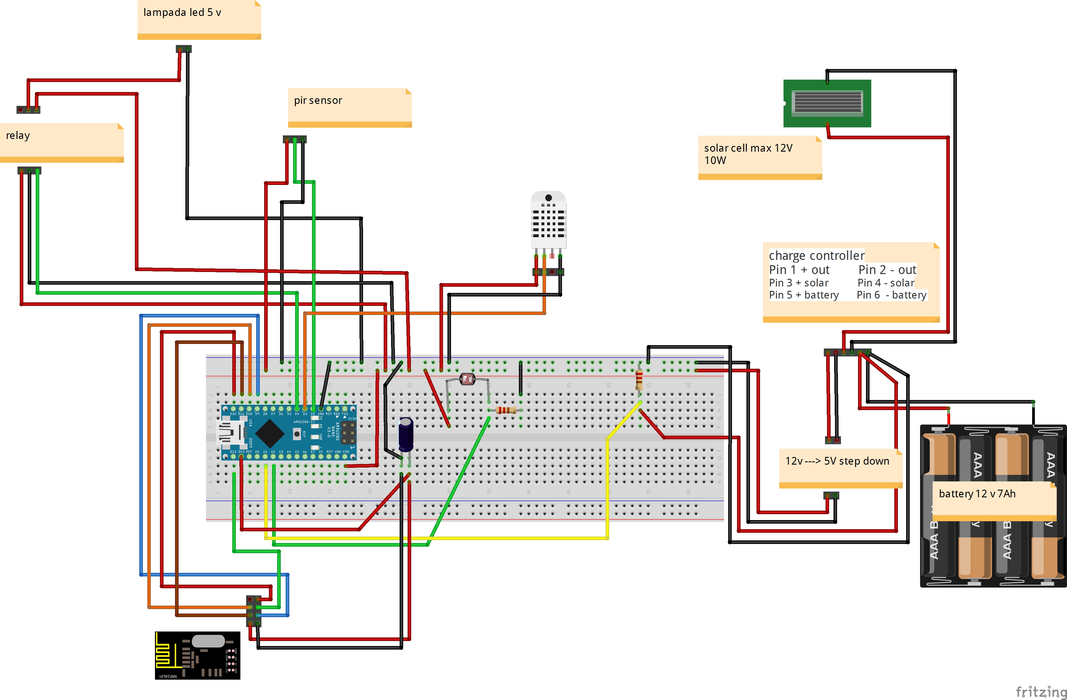
landstar solar charge controllerI want to insert into Arduino in output of charge controller (I have 12 volts)
to lower the voltage can I use a mobile charger Car 1 Ah
do you heat so much?
Thank
@Salmoides Good Project!!!!!
-
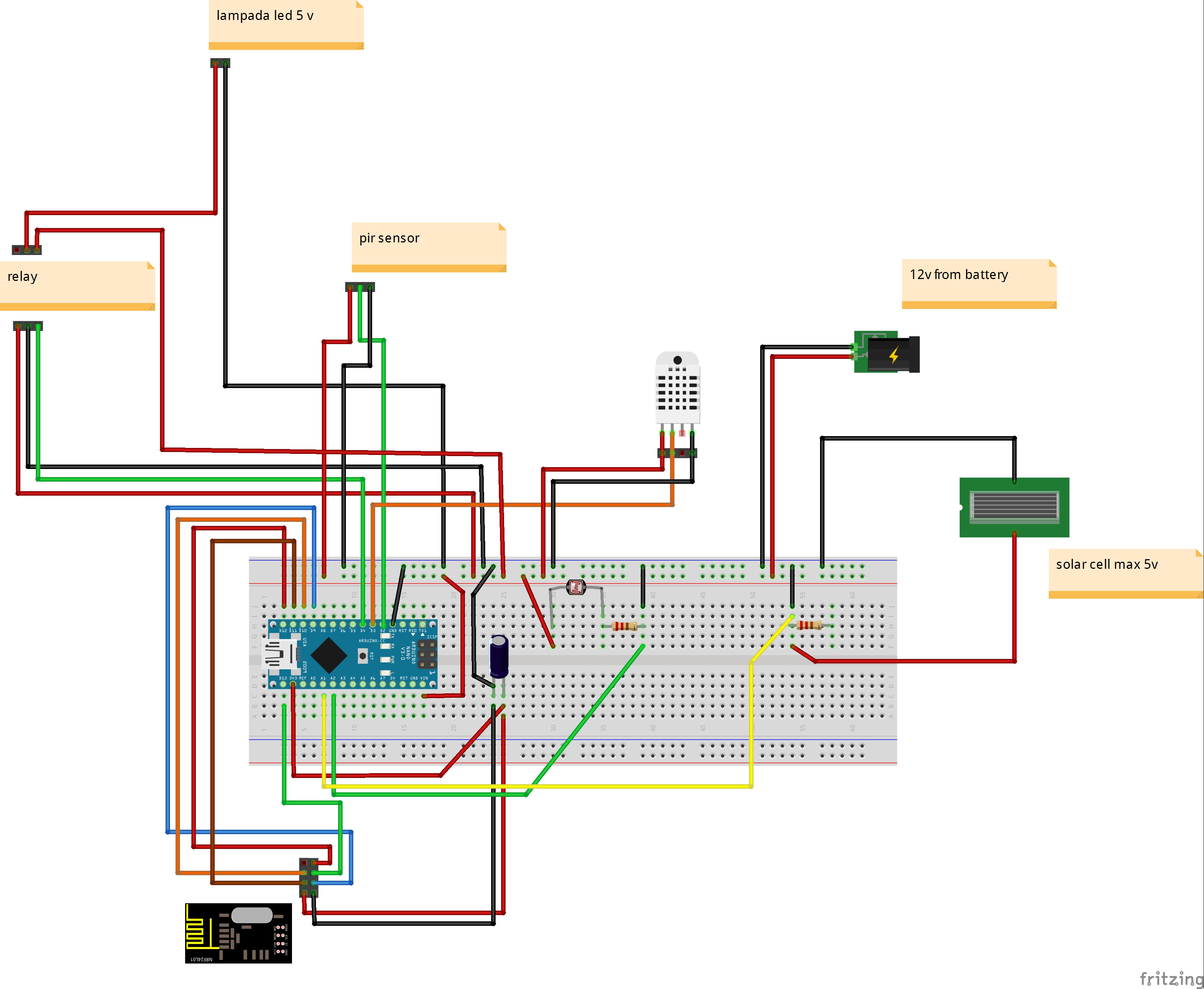
New fritzing
I have two questions?
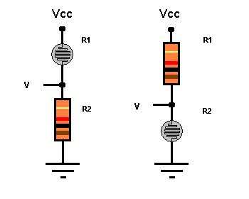
- voltage divider for more 5 v (battery voltage 12-13 volts)
- I use a auto phone charger for step down (12v --> 5 V) - warmers if I close in a box?
Thank
Vera lite - mysensors Ethernet gateway - AirWik sensor - Relay Module
-
New fritzing
I have two questions?
- voltage divider for more 5 v (battery voltage 12-13 volts)
- I use a auto phone charger for step down (12v --> 5 V) - warmers if I close in a box?
Thank
@gigi said:
New fritzing
I have two questions?
- voltage divider for more 5 v (battery voltage 12-13 volts)
- I use a auto phone charger for step down (12v --> 5 V) - warmers if I close in a box?
Thank
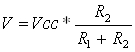
Is your fritzing correct?
On the green wire (light sensor?) you measure on ground where I guess you should measure between the resistor and the sensor. -
@gigi said:
New fritzing
I have two questions?
- voltage divider for more 5 v (battery voltage 12-13 volts)
- I use a auto phone charger for step down (12v --> 5 V) - warmers if I close in a box?
Thank
Is your fritzing correct?
On the green wire (light sensor?) you measure on ground where I guess you should measure between the resistor and the sensor. -
Back to the weather station.
I was having problems reporting wind speed to domoticz (in hardware my sensor was listed, but there was no device creation)
After a question on their forum, i learned tha i had to implement gust and direction to the sensor becaus Domoticz is aspectiong these to before it vreates a device.
I had to remove the rainrate because the sketch was getting to big.
Here is the latest sketch i am using :#include <SPI.h> #include <MySensor.h> #include <dht.h> #include <BH1750.h> #include <Wire.h> #include <Adafruit_BMP085.h> #include <MySigningAtsha204.h> #define CHILD_ID_HUM 0 #define CHILD_ID_TEMP 1 #define CHILD_ID_LIGHT 2 #define CHILD_ID_BARO 3 #define CHILD_ID_BTEMP 4 #define CHILD_ID_WINDSPEED 5 #define CHILD_ID_RAIN 6 #define MESSAGEWAIT 500 #define DIGITAL_INPUT_RAIN_SENSOR 3 #define HUMIDITY_SENSOR_DIGITAL_PIN 5 #define ENCODER_PIN 2 #define INTERRUPT DIGITAL_INPUT_RAIN_SENSOR-2 const int windSpeedPin = 2; // contact on pin 2 digital int windSpeedPinCounter = 0; // impuls counter int windSpeedPinStatus = 0; // actual impuls int windSpeedPinStatusAlt = 0; // oude Impuls-Status unsigned long windmeterStart; unsigned long windmeterStartAlt = 0; int windSpeed; // Variable voor Wind Speed int beaufort = 0; // Variable Wind in Beaufort const int windmeterTime = 10000; //float knoten = 0.0; //float wind = 0.0; unsigned int knoten; unsigned int wind; boolean metric = false; int altitude = 16; // meters above sealevel float lastBmpTemp = -1; float lastPressure = -1; float lastHum = -1; float lastTemp = -1; double temp; double hum; int BATTERY_SENSE_PIN = A0; int lastRainValue = -1; int nRainVal; boolean bIsRaining = false; String strRaining = "NO"; int lastBatteryPcnt = 0; int updateAll = 60; int updateCount = 0; uint16_t lastLux; // unsigned long SLEEP_TIME = 60000; unsigned long SLEEP_TIME = 600; int batteryBasement = 800; float batteryConstant = 100.0 / (1023 - batteryBasement); MyTransportNRF24 radio; // NRFRF24L01 radio driver MyHwATMega328 hw; // Select AtMega328 hardware profile MySigningAtsha204 signer(true); // Select HW ATSHA signing backend Adafruit_BMP085 bmp = Adafruit_BMP085(); BH1750 lightSensor; dht DHT; MySensor gw(radio, hw, signer); MyMessage msgHum(CHILD_ID_HUM, V_HUM); MyMessage msgTemp(CHILD_ID_TEMP, V_TEMP); MyMessage msgLux(CHILD_ID_LIGHT, V_LIGHT_LEVEL); MyMessage msgBtemp(CHILD_ID_BTEMP, V_TEMP); MyMessage msgPressure(CHILD_ID_BARO, V_PRESSURE); MyMessage msgWindSpeed(CHILD_ID_WINDSPEED, V_WIND); MyMessage msgWGust(CHILD_ID_WINDSPEED, V_GUST); MyMessage msgWDirection(CHILD_ID_WINDSPEED, V_DIRECTION); MyMessage msgRain(CHILD_ID_RAIN, V_TRIPPED); void setup() { analogReference(INTERNAL); gw.begin(incomingMessage, 3, true); //dht.setup(HUMIDITY_SENSOR_DIGITAL_PIN); bmp.begin(); gw.sendSketchInfo("Weather Sensor", "1.0"); gw.present(CHILD_ID_HUM, S_HUM, "WS Humidity"); gw.present(CHILD_ID_TEMP, S_TEMP, "WS Temperature"); gw.present(CHILD_ID_LIGHT, S_LIGHT_LEVEL, "WS Lux"); gw.present(CHILD_ID_BARO, S_BARO, "WS Pressure"); gw.present(CHILD_ID_BTEMP, S_TEMP, "WS P Temperature"); gw.present(CHILD_ID_WINDSPEED, S_WIND, "WS Windspeed"); gw.present(CHILD_ID_RAIN, S_MOTION, "WS Rain"); pinMode(DIGITAL_INPUT_RAIN_SENSOR, INPUT); lightSensor.begin(); metric = gw.getConfig().isMetric; } // Wind Meter https://github.com/chiemseesurfer/arduinoWeatherstation/blob/master/weatherstation/weatherstation.ino float windmeter() { windmeterStart = millis(); // Actual start time measuringMessung windmeterStartAlt = windmeterStart; // Save start time windSpeedPinCounter = 0; // Set pulse counter to 0 windSpeedPinStatusAlt = HIGH; // Set puls status High while ((windmeterStart - windmeterStartAlt) <= windmeterTime) // until 10000 ms (10 Seconds) .. { windSpeedPinStatus = digitalRead(windSpeedPin); // Read input pin 2 if (windSpeedPinStatus != windSpeedPinStatusAlt) // When the pin status changed { if (windSpeedPinStatus == HIGH) // When status - HIGH { windSpeedPinCounter++; // Counter + 1 } } windSpeedPinStatusAlt = windSpeedPinStatus; // Save status for next loop windmeterStart = millis(); // Actual time } windSpeed = ((windSpeedPinCounter * 24) / 10) + 0.5; // WindSpeed - one Pulse ~ 2,4 km/h, windSpeed = (windSpeed / (windmeterTime / 1000)); // Devided in measure time in seconds Serial.print("wind Speed : "); Serial.println(windSpeed); knoten = windSpeed / 1.852; //knot's return windSpeed; } void loop() { updateCount += 1; if (updateCount == updateAll) { lastTemp = -1; lastHum = -1; lastLux = -1; lastBmpTemp = -1; lastPressure = -1; lastRainValue = -1; lastBatteryPcnt = -1; updateCount = 0; } delay(2000); int chk = DHT.read22(HUMIDITY_SENSOR_DIGITAL_PIN); temp = DHT.temperature; //Serial.print("Temperature DHT :"); //Serial.println(temp); if (isnan(temp)) { lastTemp = -1; } else if (temp != lastTemp) { lastTemp = temp; if (!metric) { temp = temp * 1.8 + 32.0; } gw.send(msgTemp.set(temp, 1)); } hum = DHT.humidity; if (isnan(hum)) { lastHum = -1; } else if (hum != lastHum) { lastHum = hum; gw.send(msgHum.set(hum, 1)); } uint16_t lux = lightSensor.readLightLevel(); if (lux != lastLux) { gw.send(msgLux.set(lux)); lastLux = lux; } float pressure = bmp.readSealevelPressure(altitude) * 0.01; float bmptemp = bmp.readTemperature(); if (!metric) { bmptemp = bmptemp * 1.8 + 32.0; } if (bmptemp != lastBmpTemp) { gw.send(msgBtemp.set(bmptemp,1)); lastBmpTemp = bmptemp; } if (pressure != lastPressure) { gw.send(msgPressure.set(pressure, 0)); lastPressure = pressure; } bIsRaining = !(digitalRead(DIGITAL_INPUT_RAIN_SENSOR)); if(bIsRaining){ strRaining = "YES"; } else{ strRaining = "NO"; } //Serial.print("Raining?: "); //Serial.print(strRaining); //Serial.print("\t Moisture Level: "); //Serial.println(nRainVal); //http://henrysbench.capnfatz.com/henrys-bench/arduino-sensors-and-input/arduino-rain-sensor-module-guide-and-tutorial/ gw.send(msgRain.set(bIsRaining, 1)); wind = windmeter(); Serial.print("Wind : "); Serial.println(wind); int wdirection = 1; int wgust = 1; gw.send(msgWindSpeed.set(wind, 1)); gw.send(msgWGust.set(wgust, 1)); gw.send(msgWDirection.set(wdirection, 1)); int sensorValue = analogRead(BATTERY_SENSE_PIN); int batteryPcnt = (sensorValue - batteryBasement) * batteryConstant; if (lastBatteryPcnt != batteryPcnt) { gw.sendBatteryLevel(batteryPcnt); lastBatteryPcnt = batteryPcnt; } gw.sleep(SLEEP_TIME); } void incomingMessage(const MyMessage & message) { // We only expect one type of message from controller. But we better check anyway. if (message.isAck()) { Serial.println("This is an ack from gateway"); } }regards Peer
-
Hi,
It means that there is no possibility to implement wind speed on this weather station... ok.
I've just received the good Li-Ion charging component, I can continue with the construction!I'll post if I will be facing for some trouble, or when it will be finished.
-
I remember having one of those beginner electronic kits when I was young and I was so excited the day I listened to our local radio station with the crystal radio I built with the kit. Decades later now, I’m finally re-living my childhood with MySensors. It was fun back then and it is again. I’m definitely a noob at this, I’m not an electrical engineer, but I have a knack for adopting the work of others and applying it to my own world. So to start off this project, I first need to thank Hek and all the other more knowledgeable and capable people that have developed what I use. This is really fun.
Many of the MySensor projects are weather related, and this one is no different. I figured if I can do simple sensoring, I’ll learn the basics necessary to move on to the more advanced technologies. I am so new to this that I had to buy a soldering iron and learn how to use it. Research and practice are all part of this, and to that end I’ve already built my Vera Serial Gateway and my first sensor – a battery powered temperature and humidity sensor that sits in my kitchen. This project is my attempt to extend that knowledge to a mini-weather station that operates outdoors.
My requirements were simple: 1) Build an inexpensive outdoor weather station, 2) Use the low-power battery features found in the MySensors Arduino libraries, and 3) Integrate it into my Vera home automation environment. I first put a list together of the components I could put into the weather station to comply with my first requirement. The list goes as follows (I’ve been using eBay, usually in lots of 10):
- Arduino Pro Mini 3.3v 8MHz processor @ $2.50 USD
- NRF24L01+ Transceiver @ $0.90
- DHT22 Humidity & Temperature sensor @ $3.50
- BMP180 Barometric Pressure sensor @ $1.70
- BH1750FVI Ambient Light Intensity sensor @ $2.10
- Rain Sensor Module @ $1.30
The weather station components total $12.00 USD without power and a project box. Humidity was actually the most expensive piece given that the BMP180 also provides temperature. The DHT11 is less costly, but doesn’t really provide the range for an outdoor sensor. I did look at adding some other sensors. For another $10 I could add Ultraviolet sensing, for $25 I could put in a lightning sensor, $45 for wind speed, and even more for wind direction and a rain gauge. All those others would be great to have, but too costly for this project. I might try my hand at building an anemometer to add to this, and I see others are working on rain gauges, but those are projects for another day.
I then needed power and an enclosure. I could have put them in a large waterproof box ($2.70), a three cell AA battery holder ($0.80), and some DuraRabbit batteries for a year ($3.00). For an additional $6.50, I was ready to go. Oh, did I mention I was lazy? I don’t really want to swap out the batteries every six months (or less), so I decided to splurge and go the solar route.
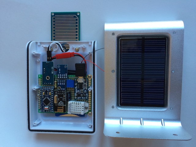
Add a 5v solar panel ($3.35) and a 3.7v 1000mAh li-ion battery ($3.75), and some way to charge the battery (Micro USB 5V 1A 18650 Lithium Battery Charger Board With Protection Module @ $0.75) instead, and my total project cost went to $22.55. Of that, over $10 went to the box, the panel and charger, and the battery. Then I found this.
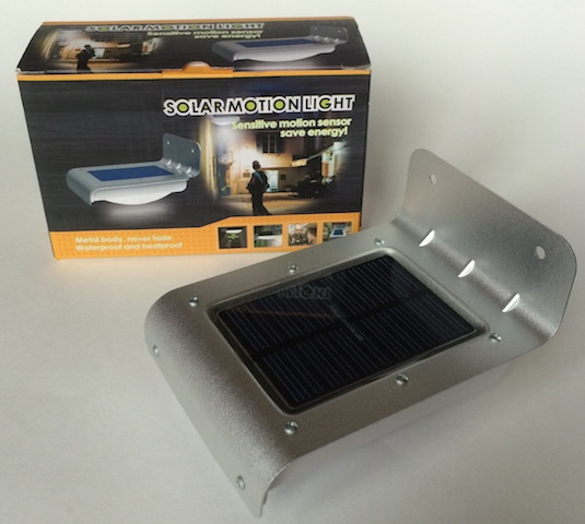
It’s entitled “16 LED Solar Power Motion Sensor Security Lamp Outdoor Waterproof Light” (http://www.ebay.com/itm/271693521438) that you can get for $9.00. I now had a $21 weather station ready to be built.
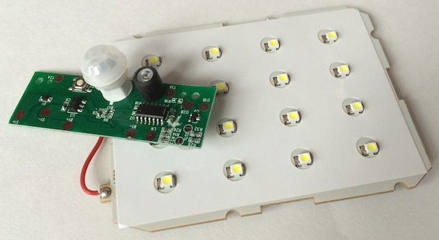
Taking apart the lamp, I removed the LED panel (worth at least $2.00) and the control board (this has some good stuff on it like a PIR, a light sensor, and the battery charging circuitry, but its use is well beyond my skills), and put them away for another project.
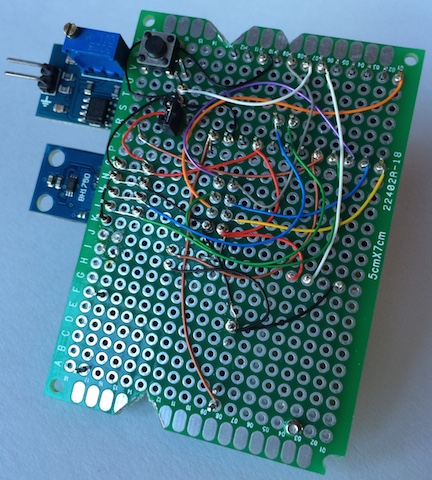
I took a 5x7cm fiberglass PCB and cut a few notches in the sides so the board would fit within the new project case. Using the mounting screws that held the LED board down, I had a good way to affix the circuit board to the case.
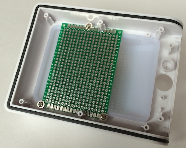
Next, I laid out how to cram all these components (including the R1 at 1MΩ & R2 [a 3296W potentiometer 500kΩ] resistors for the voltage divider to track battery voltage and the capacitor for the radio) into the enclosure. I ended up with a tight fit, but very manageable.
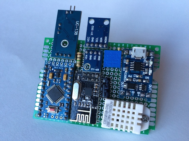
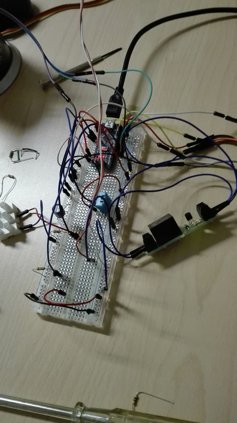
One rule I’ve learned is to always breadboard all the components and measure the performance. This is where I check the current being used during the sleep mode and I get to test my preliminary sketch. It is a very good use of my time as I’ve come upon some bad components in what little of this that I’ve done and this is where they can be identified.
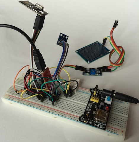
When I started learning the how-to’s of this hobby, I bought all sorts of stuff. One of the first purchases was one of those boxes of 22-gauge wire. The first one was stranded, so then I had to try solid to see if it was any easier to work with. It is, but is still huge compared to what is needed for these low-current projects. I found some old computer cables that had 26-gauge stranded in them. Better, but not what I wanted. Finally I came upon some discussions of wire-wrapping. I now use 30-gauge solid, first installed with a wire-wrapping tool (what a scam and I even found a cheap one for less than $20.)
I decided to add two additional features after breadboarding the circuit. First, I wanted a reset button that could be reached without taking the case apart. At times I’ve found my sensors need a quick reboot. A switch was added to the underside of the PCB and a hole in the underside of the case will allow me to use a paperclip to do a reset.
The other feature I added was a jumper that I could use to enable or disable the rain sensor if I chose to at a later date. For some reason it adds a significant load to the circuit. Without the rain sensor enabled, the circuit idles at 270 µA. With it I get 0.98 mA during the gw.sleep command. If I was smart enough, I’m sure I could get that down, but that’s still something to be learned. The underside, as usual, looked like spaghetti.
After a little bit of solder (I’m actually getting pretty good at that part), I have a fully functional circuit. Since the Li-Ion charging component takes a micro-USB connection, I charged the battery fully and then adjusted the pot to get the AO output to be right at 1023. For this setup my voltmeter showed the battery at 4.15v. I then needed to calibrate the circuit to get to the lower end of the acceptable voltage range. I’ve seen several different numbers for the bottom end of a 3.7v li-ion battery, some down to 2.7v. I chose 3.3v as my lowest acceptable value and proceeded to drain the battery (those LED arrays came in handy after all) down to 3.0v to see what the circuit value came out to be. For my setup, at 3.3v I was getting a value of 800 from pin A0. I updated the sketch so that it would be equal to 0% (hopefully it never gets there.)
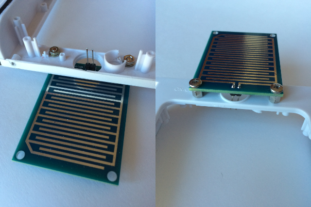
I had one addition to make to the project case. The rain sensor has a board that needs to be exposed to the elements. I drilled a couple of holes in the front end of the case and found some connectors that would work. The hole in the original case for the PIR sensor was a great opening to pass the cable through. The results actually look pretty good, if I can say so myself.
A couple of last minute touch-ups: two holes in the lens of the light, one for the reset button and one for the pot that adjusts the sensitivity of the rain sensor. I also take off any LEDs on the circuit, even LED13 on the Arduino. Every little bit helps. Does an LED actually illuminate if no one is there to see it? The final product came out nice.
One last upload of the final sketch. I took all the weather prediction logic out of the pressure sketch to save room for the other components. The SLEEP_TIME parameter is set for once every minute. I also added some lines of code to have the sensor update all measurements once an hour. I really like the ability to see when a measurement was last updated. That’s a nice touch to the MySensors library.
    #include <SPI.h>
    #include <MySensor.h>
    #include <DHT.h>
    #include <BH1750.h>
    #include <Wire.h>
    #include <Adafruit_BMP085.h>

    #define CHILD_ID_HUM 0
    #define CHILD_ID_TEMP 1
    #define CHILD_ID_LIGHT 2
    #define CHILD_ID_BARO 3
    #define CHILD_ID_BTEMP 4
    #define CHILD_ID_RAIN 5

    #define DIGITAL_INPUT_RAIN_SENSOR 3
    #define HUMIDITY_SENSOR_DIGITAL_PIN 4
    #define INTERRUPT DIGITAL_INPUT_RAIN_SENSOR-2

    boolean metric = false;
    int altitude = 221; // 741 feet above sealevel
    float lastBmpTemp = -1;
    float lastPressure = -1;
    float lastHum = -1;
    float lastTemp = -1;
    int BATTERY_SENSE_PIN = A0;
    int lastRainValue = -1;
    int lastBatteryPcnt = 0;
    int updateAll = 60;
    int updateCount = 0;
    uint16_t lastLux;
    unsigned long SLEEP_TIME = 60000;
    int batteryBasement = 800;
    float batteryConstant = 100.0 / (1023 - batteryBasement);

    Adafruit_BMP085 bmp = Adafruit_BMP085();
    BH1750 lightSensor;
    DHT dht;
    MySensor gw;

    MyMessage msgHum(CHILD_ID_HUM, V_HUM);
    MyMessage msgTemp(CHILD_ID_TEMP, V_TEMP);
    MyMessage msgLux(CHILD_ID_LIGHT, V_LIGHT_LEVEL);
    MyMessage msgBtemp(CHILD_ID_BTEMP, V_TEMP);
    MyMessage msgPressure(CHILD_ID_BARO, V_PRESSURE);
    MyMessage msgRain(CHILD_ID_RAIN, V_TRIPPED);

    void setup()
    {
      analogReference(INTERNAL);
      gw.begin();
      dht.setup(HUMIDITY_SENSOR_DIGITAL_PIN);
      bmp.begin();
      gw.sendSketchInfo("Weather Sensor", "1.0");
      gw.present(CHILD_ID_HUM, S_HUM);
      gw.present(CHILD_ID_TEMP, S_TEMP);
      gw.present(CHILD_ID_LIGHT, S_LIGHT_LEVEL);
      gw.present(CHILD_ID_BARO, S_BARO);
      gw.present(CHILD_ID_BTEMP, S_TEMP);
      gw.present(CHILD_ID_RAIN, S_MOTION);
      pinMode(DIGITAL_INPUT_RAIN_SENSOR, INPUT);
      lightSensor.begin();
      metric = gw.getConfig().isMetric;
    }

    void loop()
    {
      updateCount += 1;
      if (updateCount == updateAll) {
        lastTemp = -1;
        lastHum = -1;
        lastLux = -1;
        lastBmpTemp = -1;
        lastPressure = -1;
        lastRainValue = -1;
        lastBatteryPcnt = -1;
        updateCount = 0;
      }
      delay(dht.getMinimumSamplingPeriod());
      float temperature = dht.getTemperature();
      if (isnan(temperature)) {
          lastTemp = -1;
      } else if (temperature != lastTemp) {
        lastTemp = temperature;
        if (!metric) {
          temperature = temperature * 1.8 + 32.0;
        }
        gw.send(msgTemp.set(temperature, 1));
      }
      float humidity = dht.getHumidity();
      if (isnan(humidity)) {
          lastHum = -1;
      } else if (humidity != lastHum) {
          lastHum = humidity;
          gw.send(msgHum.set(humidity, 1));
      }
      uint16_t lux = lightSensor.readLightLevel();
      if (lux != lastLux) {
          gw.send(msgLux.set(lux));
          lastLux = lux;
      }
      float pressure = bmp.readSealevelPressure(altitude) * 0.01;
      float bmptemp = bmp.readTemperature();
      if (!metric) {
        bmptemp = bmptemp * 1.8 + 32.0;
      }
      if (bmptemp != lastBmpTemp) {
        gw.send(msgBtemp.set(bmptemp,1));
        lastBmpTemp = bmptemp;
      }
      if (pressure != lastPressure) {
        gw.send(msgPressure.set(pressure, 0));
        lastPressure = pressure;
      }
      int rainValue = digitalRead(DIGITAL_INPUT_RAIN_SENSOR);
      if (rainValue != lastRainValue) {
        gw.send(msgRain.set(rainValue==0?1:0));
        lastRainValue = rainValue;
      }
      int sensorValue = analogRead(BATTERY_SENSE_PIN);
      int batteryPcnt = (sensorValue - batteryBasement) * batteryConstant;
      if (lastBatteryPcnt != batteryPcnt) {
        gw.sendBatteryLevel(batteryPcnt);
        lastBatteryPcnt = batteryPcnt;
     }
      gw.sleep(SLEEP_TIME);
    }
Then a test to make sure it’s dumping out its results as it should
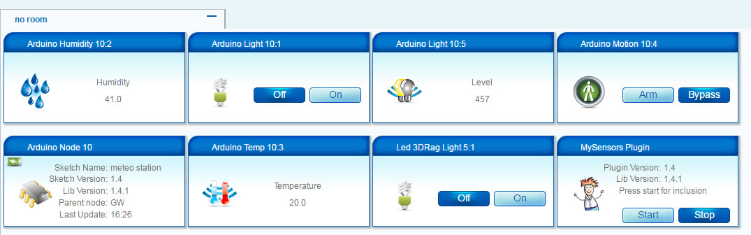
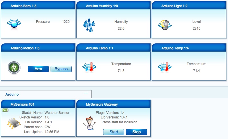
    sensor started, id 1
    send: 1-1-0-0 s=255,c=0,t=17,pt=0,l=5,st=ok:1.4.1
    send: 1-1-0-0 s=255,c=3,t=6,pt=1,l=1,st=ok:0
    read: 0-0-1 s=255,c=3,t=6,pt=0,l=1:I
    send: 1-1-0-0 s=255,c=3,t=11,pt=0,l=14,st=ok:Weather Sensor
    send: 1-1-0-0 s=255,c=3,t=12,pt=0,l=3,st=ok:1.0
    send: 1-1-0-0 s=0,c=0,t=7,pt=0,l=5,st=ok:1.4.1
    send: 1-1-0-0 s=1,c=0,t=6,pt=0,l=5,st=ok:1.4.1
    send: 1-1-0-0 s=2,c=0,t=16,pt=0,l=5,st=ok:1.4.1
    send: 1-1-0-0 s=3,c=0,t=8,pt=0,l=5,st=ok:1.4.1
    send: 1-1-0-0 s=4,c=0,t=6,pt=0,l=5,st=ok:1.4.1
    send: 1-1-0-0 s=5,c=0,t=1,pt=0,l=5,st=ok:1.4.1
    send: 1-1-0-0 s=1,c=1,t=0,pt=7,l=5,st=ok:80.8
    send: 1-1-0-0 s=0,c=1,t=1,pt=7,l=5,st=ok:28.2
    send: 1-1-0-0 s=2,c=1,t=23,pt=3,l=2,st=ok:83
    send: 1-1-0-0 s=4,c=1,t=0,pt=7,l=5,st=ok:80.6
    send: 1-1-0-0 s=3,c=1,t=4,pt=7,l=5,st=ok:1020
    send: 1-1-0-0 s=5,c=1,t=16,pt=2,l=2,st=ok:0
    send: 1-1-0-0 s=255,c=3,t=0,pt=1,l=1,st=ok:91
Finally, we then go to Vera and make sure she’s happy.
This has been a great learning experience for me as it’s my first documented project. I made a bunch of mistakes in between most of the steps you see here. I’ve practiced my soldering techniques for many, many hours. One battery went bye-bye when I didn’t notice the leads had crossed. The smoke was a real good indicator that I’d messed up. I’ve ruined my fair share of components, but I chalk it all up to experience and don’t dwell on them. This hobby is a lot less expensive than golf or fishing, even with my mistakes. I look forward to bigger and better as I continue learn. Thanks again, Hek. This is a hobby that I truly enjoy.
@Salmoides - I must congratulate you on a very neat and professional build.
I'm not sure if you are still hanging around this forum but even if you aren't, others may find the following suggestion helpful.
@Salmoides said*:
With it [the rain detector] I get 0.98 mA [drain] during the gw.sleep command
There is a very easy, but often overlooked, method to disable sensors to reduce battery drain that requires no additional components. Because the sensor draws approximately 1ma, that is well within the 'drive' capacity of an Arduino output pin (which is about 20ma). So, all you need to do is wire the "+" power pin of the rain sensor to a spare output pin and "digitalWrite(pin,HIGH)" to turn it on and "digitalWrite(pin,LOW)" to turn it off.
IMPORTANT: You should check the specs of the processor you are using to make sure the I/O pin can 'drive' or 'source' more than the required current of the sensor you wish to switch. I'd suggest allowing a 50% safety margin.
Paul
-
Looks like a feasible idea, as my stn does consume all the battery on bad days, and yes I needed the diode between the solar and controller to get to the right voltage
cheers doug
-
Hello, it a nice job
I am french so I beg your pardon for my poor English
Can you , please show me how the lipo and the solar cell are connected and how the arduino is powered by the little shield (Charger Board ) at the right of picture over the DHT ?
Thanks -
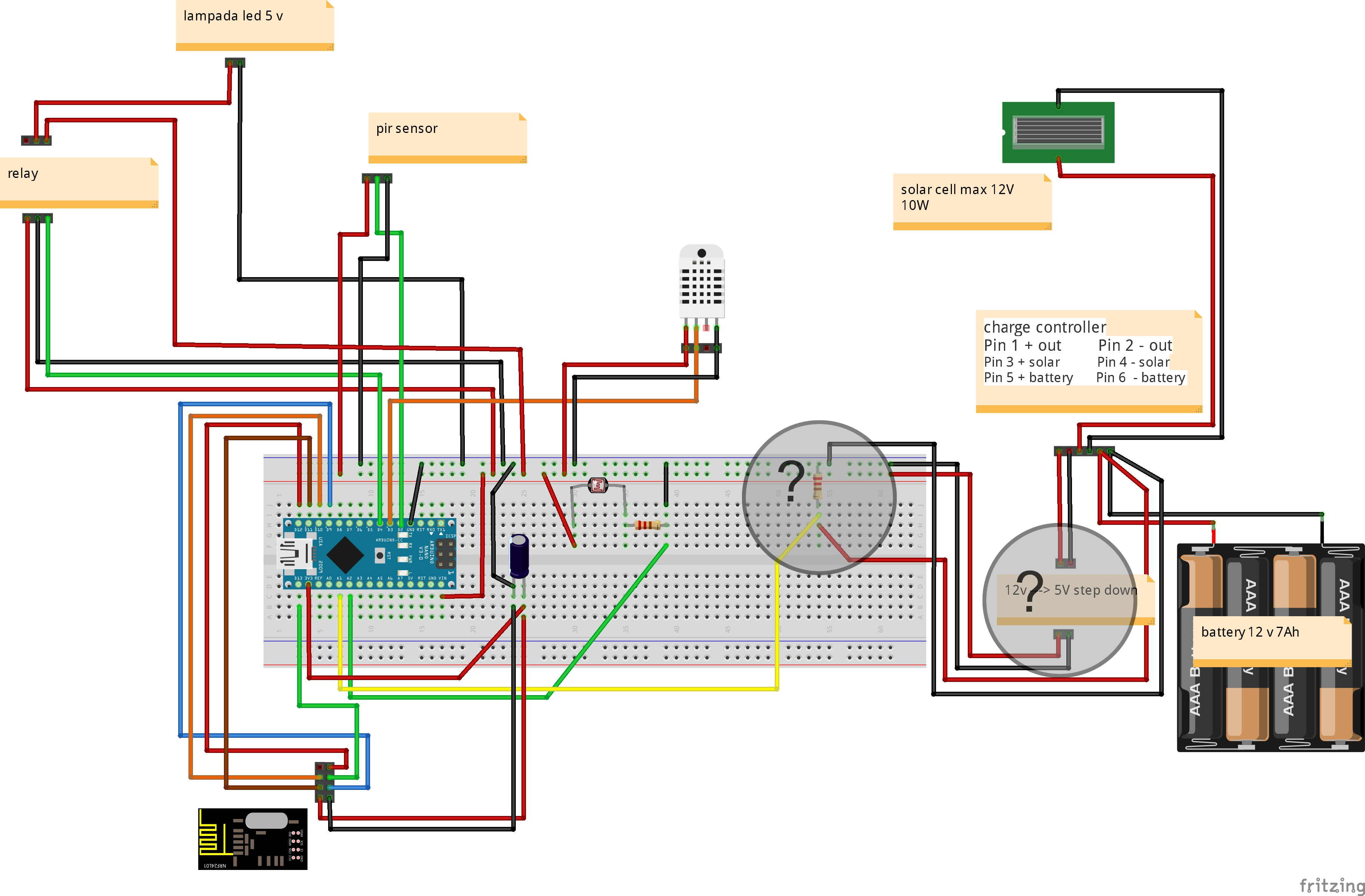
@gigi: Besides the already adressed error in the Fritzing I have anaother question. In the diagram there is a charge controller for 12V. The original design in this threat uses a 5V charging module. What module are you using or planning to use?
Thanks Ralph -
@Renard : Bonjour! Je fais le raccordement cette semaine j'espère, je galère sur la déclaration dans Domoticz et l'étalonnage pour controler la charge de la batterie, mais je dirais:
- OUT+ et - sur RAW et GND de l'Arduino
- B+ B- à la batterie
- "+ et -" au panneau solaire, c'est ce qu'il me semble sur les photos.
@bisschopsr : Hi, There is no charge controler 5 or 12 volts. On my Fritzing to understand better the scheme (Post #70), I draw batteries and solar panel, but Fritzings following are with 12volts charger, I don't know why. If you purchased a solar lamp, it's to avoid 5 or 12volts charger and use the sun ;-)
-
Merci pour la réponse
C 'est donc l'arduino qui gère la décharge..
Je vais donc mettre "Arduino Compatible Solar Charger shield -LiPo rider" a la place ...Thanks for answer
It is the arduino wich control the discharge
I put "Arduino Compatible Solar Charger shield -LiPo rider" without control of lipo capacity