CNC PCB milling
-
No offence but upgrading with dro, ballscrew, stronger stepper, beefier driver, you end up with more cost than buying a real cnc platform like 3020 or 3040 😁
That machine has great results for its price, maybe relaxing tolerances a bit in design and using larger bits would achieve better predictibility.
Happy new year! Happy new toys! -
Not sure why I'd have to buy a bigger machine in order to get quality parts, yet it is true that none of the 2418 kits appear to come with ballscrews. Strange how that is. In terms of just size alone, though, the 2418 seems about right for etching hobbyist circuit boards. If anything, it could be a little smaller. Does the sheer mass of the bigger machines somehow help with accuracy (maybe less vibration for instance)?
The ballscrews themselves, and even the linear scales, don't seem all that expensive, which is why I thought maybe upgrading even just the z-axis might make sense.
If nothing else, replacing the stepper motor with either a larger stepper motor (less skipping) or some kind of servo equivalent might at least put a cap on how far off the z-axis is from what is assumed. In that case, I would think the maximum error would less than or equal to the maximum possible backlash.
Anyhow, any suggestions appreciated.
-
I'll need an adapter plate to go from Nema 17 to Nema 23. Will the existing motor drivers be able to handle a Nema 23?
-
Well, maybe the simplest upgrade would be to upgrade to a higher torque nema 17 motor, such as:
https://www.aliexpress.com/item/Nema17-stepper-motor-60mm-length-1-7A-0-73Nm-7-3kg-cm-104Oz-in-High-torque/32727142878.html?spm=2114.search0104.3.1.RoU5IE&ws_ab_test=searchweb0_0,searchweb201602_2_10152_10065_5000015_10151_10344_10068_10130_10324_10342_10547_10325_10343_51102_10546_10340_10548_10341_10545_5130015_10084_10083_10307_5920012_10312_10059_10313_10314_10534_5790011_100031_10604_10103_10594_5060015_10142,searchweb201603_2,ppcSwitch_5&algo_expid=31255370-90b4-4695-94c0-997d9d68e388-0&algo_pvid=31255370-90b4-4695-94c0-997d9d68e388&rmStoreLevelAB=5or
or perhaps even
Not sure what kind of impact it might have on the feedrate....
The idea is that the higher torque would eliminate missed steps, provided that the feedrate is low enough.
-
@neverdie
I think you should start by altering the acceleration/Max velocity settings etc in grbl.
Slow them down a little:grinning:@rmtucker said in CNC PCB milling:
I think you should start by altering the acceleration/Max velocity settings etc in grbl.
I don't see those parameters exposed in flatcam or in chilipeppr either. I guess I have to set them by issuing the grbl commands manually?
-
@rmtucker said in CNC PCB milling:
I think you should start by altering the acceleration/Max velocity settings etc in grbl.
I don't see those parameters exposed in flatcam or in chilipeppr either. I guess I have to set them by issuing the grbl commands manually?
-
Would this be something good to do? https://www.youtube.com/watch?v=7rVmiRgsI1M
Cut a complete flat peace of wood with the cnc machine? -
@neverdie
I think you should start by altering the acceleration/Max velocity settings etc in grbl.
Slow them down a little:grinning:@rmtucker said in CNC PCB milling:
@neverdie
I think you should start by altering the acceleration/Max velocity settings etc in grbl.
Slow them down a little:grinning:This was good advice! I arbitrarily reduced both to 50% of their default values, and so far it appears that repositional accuracy has improved.
-
Normally i would turn one up at a time until the motors lose steps,then pull them back 20%.
@rmtucker How are you noticing when the motor skips? Is it from noticing a delta in test probe depths?
Also, what's a reasonable target for repositioning accuracy? i.e. if I set z to zero after doing a test probe, then move it around a bunch, and then return to the same x and y position and drop another test probe, how far off from zero is the second test probe? Presently I only have a few datapoints, but so far it's suggesting maybe a maximum of 0.025mm after having done the 50% reductions, whereas before the reductions (i.e. default values) it was more than 0.05mm (maybe a lot more), which is just too much.

-
@rmtucker How are you noticing when the motor skips? Is it from noticing a delta in test probe depths?
Also, what's a reasonable target for repositioning accuracy? i.e. if I set z to zero after doing a test probe, then move it around a bunch, and then return to the same x and y position and drop another test probe, how far off from zero is the second test probe? Presently I only have a few datapoints, but so far it's suggesting maybe a maximum of 0.025mm after having done the 50% reductions, whereas before the reductions (i.e. default values) it was more than 0.05mm (maybe a lot more), which is just too much.
@neverdie
Hmmm how long is a piece of string.:grinning:
My machine is on a much larger scale but the principal is the same.
Is this a mechanical inaccuracy or lost steps?
Make yourself a small program that rapids each axis in turn from one end of the axis to
the other.
On my own machine the motors are running pulleys to the leadscrews/ballscrews.
I place a mark on the pulleys and a pointer (pin and blue tac) when the machine is at 0,0,0.
I run the program and adjust the accel and velocity returning to 0,0,0 every time and checking the marks always line up.(If they don't lowering the settings 10% and running again).
Which eventually proves it is not lost steps. -
@rmtucker How are you noticing when the motor skips? Is it from noticing a delta in test probe depths?
Also, what's a reasonable target for repositioning accuracy? i.e. if I set z to zero after doing a test probe, then move it around a bunch, and then return to the same x and y position and drop another test probe, how far off from zero is the second test probe? Presently I only have a few datapoints, but so far it's suggesting maybe a maximum of 0.025mm after having done the 50% reductions, whereas before the reductions (i.e. default values) it was more than 0.05mm (maybe a lot more), which is just too much.
-
@neverdie once the assembly is done, you should adjust the stepper drivers' current limiting as well.
it is pololu a4988, you can find the corresponding details here:
https://www.pololu.com/product/1182then, it is always good idea to have the basic settings exported from the board, just in case... you can do it by "$$" command sent from the g code sender gui or directly from the serial terminal.
currently I use the following settings, the machine might be able to create nice results with higher feed rates, but I did not have enough time to test it and I sticked to the current working config.
isolation routing with 2001 bits:
- z cut: -0.05mm
- feed rate: 200
you can calculate the V carving bit's tool width for the given milling depth with the following formula:
tan(bit angle/2) * milling depth * 2 + bit's end width
for excel formula the bit angle should be provided in radians, so it should look like this
tan(radians(bit angle/2)) * milling depth * 2 + bit's end widthedge cut or hole milling with the 0.8mm endmill:
- feed rate: 170
- z cut: -1.7mm
- multi depth, depth/pass: 0.2mm
drilling:
- feed rate: 130
- z cut: -1.8
the spindle should be 1000 everywhere.
most probably your board will not have a bootloader, so it will not be possible to update the firmware via usb serial connection (with avrdude), but it is worth to try it. for me it did not work, so I traced back the MCU pins to the pin rows and used ISP to upgrade the firmware to grbl v1.1f (the board will come with 0.9j if I remember correctly). do not forget to export the gerber settings before you upgrade the firmware, as it will loose those, and you have to re-assign the given values again, after the update.
the ISP pinout (from the pin row's top left corner):
Reset -> pin 2
SCK -> pin 3
MISO -> pin 12
MOSI -> pin 135v -> pin1
gnd-> bottom row(!) e.g. pin 1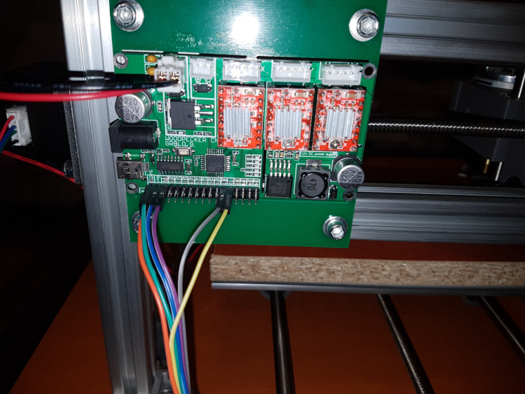
@andrew said in CNC PCB milling:
@neverdie once the assembly is done, you should adjust the stepper drivers' current limiting as well.
it is pololu a4988, you can find the corresponding details here:
https://www.pololu.com/product/1182Wow, those Pololu directions bear an uncanny resemblance to this:
https://www.youtube.com/watch?v=lAdvdX88WDsJokes aside, the Jack stepper motors appear to be rated at 1.3A. @andrew Is that what you assumed when calibrating yours? If so, what Vref did you use? Since the motor driver board is a knock-off, it's not obvious what current sense resistor value to use. i.e. 0.050 ohm, 0.068 ohm, or something else?
-
@andrew Are you planning to provide more detail about how to setup and do double sided PCBs, or is it pretty much RTFM at this point? Just wondering. Your earlier posts were very thorough and helped a lot.
@neverdie said in CNC PCB milling:
@andrew Are you planning to provide more detail about how to setup and do double sided PCBs, or is it pretty much RTFM at this point? Just wondering. Your earlier posts were very thorough and helped a lot.
did you manage to create double sided PCB jobs in the meantime based on my suggestion and on flatcam's documentation? it is not a hardcore process, let me know if you stuck at a given step.
regarding to the mentioned upgrades. I agree with @executivul, it doesn't worth to do that with this machine. feedback from steppers, elevation measuring etc are overkill.
it's capabilities are more than enough for very precise pcb milling, if you would like to do much more with it, then a different machine could be better instead. if you have issues with the results, then it is configuration / settings / cnc job issue. if you loose steps, then the given stepper driver is not properly adjusted (did you checked the pololu driver configuration from the linked documentation?) or your tool/spindle speed/cutting depth/feed rate is not good for the given job.
-
@neverdie said in CNC PCB milling:
@andrew Are you planning to provide more detail about how to setup and do double sided PCBs, or is it pretty much RTFM at this point? Just wondering. Your earlier posts were very thorough and helped a lot.
did you manage to create double sided PCB jobs in the meantime based on my suggestion and on flatcam's documentation? it is not a hardcore process, let me know if you stuck at a given step.
regarding to the mentioned upgrades. I agree with @executivul, it doesn't worth to do that with this machine. feedback from steppers, elevation measuring etc are overkill.
it's capabilities are more than enough for very precise pcb milling, if you would like to do much more with it, then a different machine could be better instead. if you have issues with the results, then it is configuration / settings / cnc job issue. if you loose steps, then the given stepper driver is not properly adjusted (did you checked the pololu driver configuration from the linked documentation?) or your tool/spindle speed/cutting depth/feed rate is not good for the given job.
@andrew said in CNC PCB milling:
did you checked the pololu driver configuration from the linked documentation?
See post immediately above yours.
-
I guess measuring Vref is moot, because jack's stepper motor driver included in the kit (https://www.aliexpress.com/store/product/board/424291_32807192686.html?spm=2114.12010612.0.0.e009a31x1CJ1s) does not have an exposed via hole for measuring Vref.
So, that leaves the first Pololu method, which is:
The A4988 supports such active current limiting, and the trimmer potentiometer on the board can be used to set the current limit. One way to set the current limit is to put the driver into full-step mode and measure the current running through a single motor coil while adjusting the current limit potentiometer. This should be done with the motor holding a fixed position (i.e. without clocking the STEP input). Note that the current you are measuring is only 70% of the actual current limit setting, since both coils are always on and limited to this value in full-step mode, so if you later enable microstepping modes, the current through the coils will be able to exceed this measured full-step current by 40% (1/0.7) on certain steps; please take this into account when using this method to set the current limit. Also, note that you will need to perform this adjustment again if you ever change the logic voltage, Vdd, since the reference voltage that sets the current limit is a function of Vdd.So, it would appear that in order to put the driver into "single step mode," I must remove the driver board and put it into a test jig (or breadboard) which shorts MS1, MS2, AND MS3 to ground, but otherwise wire up the motor according to this diagram:
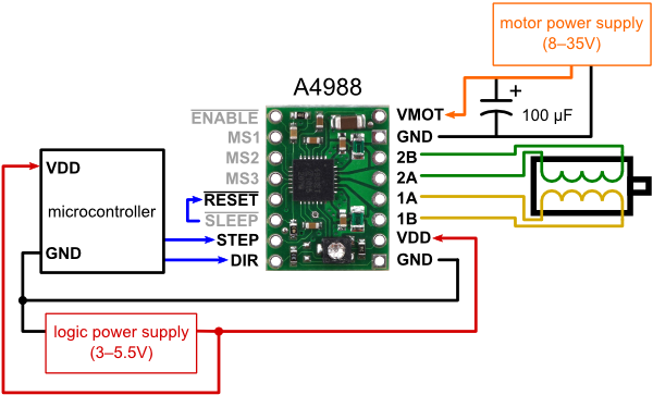
but connecting the STEP pin to Vcc on the logic power supply (?) so as to allow a fixed, but continuous, current through a single motor coil, which is what will be measured.As to the target current through a single coil that I'll be measuring, I guess it should be (0.7)*1.3=0.91amps?
-
@andrew said in CNC PCB milling:
did you checked the pololu driver configuration from the linked documentation?
See post immediately above yours.
@neverdie said in CNC PCB milling:
@andrew said in CNC PCB milling:
did you checked the pololu driver configuration from the linked documentation?
See post immediately above yours.
ok, I thought that you already did it, I told it to you long time ago ;)
my controller has 0.1ohm Rcs. the steppers are rated to 1.3A, I configured the drivers to 0.9V which limits the stepper's current to 1.125A.
-
I guess measuring Vref is moot, because jack's stepper motor driver included in the kit (https://www.aliexpress.com/store/product/board/424291_32807192686.html?spm=2114.12010612.0.0.e009a31x1CJ1s) does not have an exposed via hole for measuring Vref.
So, that leaves the first Pololu method, which is:
The A4988 supports such active current limiting, and the trimmer potentiometer on the board can be used to set the current limit. One way to set the current limit is to put the driver into full-step mode and measure the current running through a single motor coil while adjusting the current limit potentiometer. This should be done with the motor holding a fixed position (i.e. without clocking the STEP input). Note that the current you are measuring is only 70% of the actual current limit setting, since both coils are always on and limited to this value in full-step mode, so if you later enable microstepping modes, the current through the coils will be able to exceed this measured full-step current by 40% (1/0.7) on certain steps; please take this into account when using this method to set the current limit. Also, note that you will need to perform this adjustment again if you ever change the logic voltage, Vdd, since the reference voltage that sets the current limit is a function of Vdd.So, it would appear that in order to put the driver into "single step mode," I must remove the driver board and put it into a test jig (or breadboard) which shorts MS1, MS2, AND MS3 to ground, but otherwise wire up the motor according to this diagram:
but connecting the STEP pin to Vcc on the logic power supply (?) so as to allow a fixed, but continuous, current through a single motor coil, which is what will be measured.As to the target current through a single coil that I'll be measuring, I guess it should be (0.7)*1.3=0.91amps?
-
@neverdie said in CNC PCB milling:
@andrew said in CNC PCB milling:
did you checked the pololu driver configuration from the linked documentation?
See post immediately above yours.
ok, I thought that you already did it, I told it to you long time ago ;)
my controller has 0.1ohm Rcs. the steppers are rated to 1.3A, I configured the drivers to 0.9V which limits the stepper's current to 1.125A.
@andrew said in CNC PCB milling:
ok, I thought that you already did it, I told it to you long time ago
It's done now. The default voltages had been about 0.6v. I just now raised them to 0.9v, same as yours. :)