CNC PCB milling
-
Here's the final product:
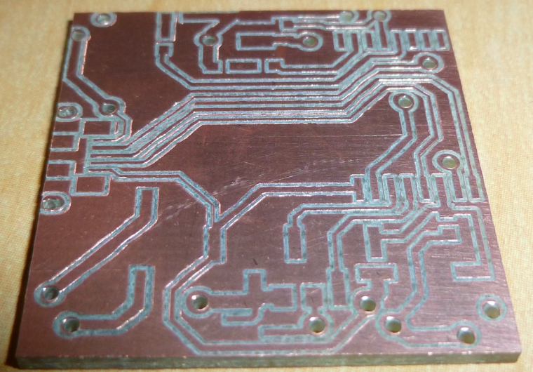
Three of the vias are located under an SMD module, so I'll just have to try to minimize any solder bumps over them.Unfortunately, even a tiny solder bump prevents the module from being soldered. I would have to redesign this so that the vias are not under the module.
-
Another good thing for people to know is that you can leave a single-sided blank PCB installed in the CNC and then, as the need arises, cut out additional modules from it:
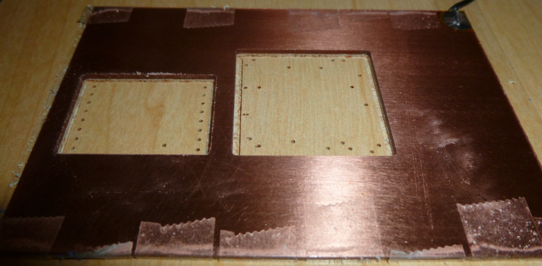
For instance, this morning I cut this module carrier out of the above, already used, copper clad PCB:
So, for simple small things, it's a handy arrangement, and the incremental cost is negligible.
-
Another good thing for people to know is that you can leave a single-sided blank PCB installed in the CNC and then, as the need arises, cut out additional modules from it:
For instance, this morning I cut this module carrier out of the above, already used, copper clad PCB:
So, for simple small things, it's a handy arrangement, and the incremental cost is negligible.
@neverdie Perhaps a clearer explanation ?
-
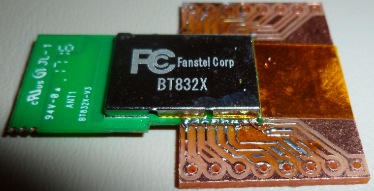
One problem I've run into though is that the foil traces can sometimes lift up in the course of ordinary soldering. For instance, the traces connecting the second to the right pin on the Fanstel module seems to have utterly disappeared, leaving that pin unconnected:
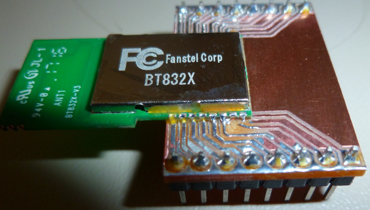
Maybe it's the quality of the blank PCB? I just don't know. -
One problem I've run into though is that the foil traces can sometimes lift up in the course of ordinary soldering. For instance, the traces connecting the second to the right pin on the Fanstel module seems to have utterly disappeared, leaving that pin unconnected:
Maybe it's the quality of the blank PCB? I just don't know.@neverdie It looks like you could potentially make those traces just a touch wider looking at the receiving end of the module. Woulld that be an option?
Vera Plus running UI7 with MySensors, Sonoffs and 1-Wire devices
Visit my website for more Bits, Bytes and Ramblings from me: http://dan.bemowski.info/ -
@neverdie It looks like you could potentially make those traces just a touch wider looking at the receiving end of the module. Woulld that be an option?
@dbemowsk said in CNC PCB milling:
Woulld that be an option?
Maybe: I'll try a 10 degree bit and tighter autoleveling to see if that gives wider traces.
-
@dbemowsk said in CNC PCB milling:
Woulld that be an option?
Maybe: I'll try a 10 degree bit and tighter autoleveling to see if that gives wider traces.
-
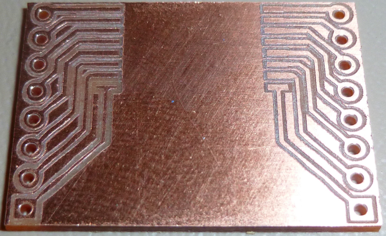
It's funny, because I redid the soldering using an altogether new board, and it failed in exactly the same place:
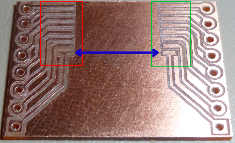
This time, though, you can actually see the copper trace has curled up away from the board.@neverdie It is quite odd that that one did it and some of the others didn't on that side of the board. Looking at your previous image, the pads and traces on the side marked in green look noticeably larger than the ones marked in red. Look at the ones marked with the blue arrow. It looks like those should, or at least could be the same size. Your thru hole pads on the left for the breakout headers also look smaller than the ones on the right. Shouldn't the two sides be a mirror image of each other?
Vera Plus running UI7 with MySensors, Sonoffs and 1-Wire devices
Visit my website for more Bits, Bytes and Ramblings from me: http://dan.bemowski.info/ -
@neverdie It is quite odd that that one did it and some of the others didn't on that side of the board. Looking at your previous image, the pads and traces on the side marked in green look noticeably larger than the ones marked in red. Look at the ones marked with the blue arrow. It looks like those should, or at least could be the same size. Your thru hole pads on the left for the breakout headers also look smaller than the ones on the right. Shouldn't the two sides be a mirror image of each other?
-
@dbemowsk It's because the left side of the board is higher than the righthand side, and apparently the autoleveling isn't working all that precisely.
@neverdie I can see that the left side looks like it cut deeper, which would cause that. I still think it is the thin traces though. Can you do any manual leveling of the bed? If so, I would attempt that. My Anet A8 3D printer, though not a CNC, is all manual leveling and I do have to check it from time to time.
Vera Plus running UI7 with MySensors, Sonoffs and 1-Wire devices
Visit my website for more Bits, Bytes and Ramblings from me: http://dan.bemowski.info/ -
@neverdie I can see that the left side looks like it cut deeper, which would cause that. I still think it is the thin traces though. Can you do any manual leveling of the bed? If so, I would attempt that. My Anet A8 3D printer, though not a CNC, is all manual leveling and I do have to check it from time to time.
@dbemowsk said in CNC PCB milling:
@neverdie I can see that the left side looks like it cut deeper, which would cause that. I still think it is the thin traces though. Can you do any manual leveling of the bed? If so, I would attempt that. My Anet A8 3D printer, though not a CNC, is all manual leveling and I do have to check it from time to time.
I suppose I could shim under the sacrifice board with slips of paper to get the right height.
I would have thought that the autoleveling would have accurately compensated though. Not sure why it isn't, especially if I'm autoleveling at 2mm spacing. Maybe this is an area where a future version of the GRBL driver will get it right.
-
@dbemowsk said in CNC PCB milling:
@neverdie I can see that the left side looks like it cut deeper, which would cause that. I still think it is the thin traces though. Can you do any manual leveling of the bed? If so, I would attempt that. My Anet A8 3D printer, though not a CNC, is all manual leveling and I do have to check it from time to time.
I suppose I could shim under the sacrifice board with slips of paper to get the right height.
I would have thought that the autoleveling would have accurately compensated though. Not sure why it isn't, especially if I'm autoleveling at 2mm spacing. Maybe this is an area where a future version of the GRBL driver will get it right.
@neverdie cnc milling auto leveling is not like 3d printing bed leveling.
In 3d printing the firmware probes the bed, stores the values and automagically compensates at every move.
In cnc milling the host control software asks the grbl to move and probe each point, then it modifies the gcode accordingly and sends that gcode to the controller which in turn just moves in the xyz coordinate system.
Now, are you sure your gcode is updated to reflect the leveling?
Normal flatcam gcode has a few Z-0.1 moves, the rest are only G1X...Y... (without Z) and autoleveled gcode has almost every move with z, like G1X...Y...Z.... Chilipeppr also adds some comments at the end of the lines like "new Z" or "Z mod".
If you run the autoleveling probing but do not hit "send autoleveled gcode to workspace" in CP or "apply height map" in OpenCNCPilot the probing is useless. -
@dbemowsk said in CNC PCB milling:
@neverdie I can see that the left side looks like it cut deeper, which would cause that. I still think it is the thin traces though. Can you do any manual leveling of the bed? If so, I would attempt that. My Anet A8 3D printer, though not a CNC, is all manual leveling and I do have to check it from time to time.
I suppose I could shim under the sacrifice board with slips of paper to get the right height.
I would have thought that the autoleveling would have accurately compensated though. Not sure why it isn't, especially if I'm autoleveling at 2mm spacing. Maybe this is an area where a future version of the GRBL driver will get it right.
@neverdie I just wasn't sure if your CNC had any way of manually leveling the bed. My 3D printer has screws in the 4 corners of the bed for me to manually level. I have been sticking to manual leveling on it because I have heard of people that have switched to auto-leveling that have had a number of problems. Maybe you need to switch to a different type of auto-leveling sensor.
-
@neverdie cnc milling auto leveling is not like 3d printing bed leveling.
In 3d printing the firmware probes the bed, stores the values and automagically compensates at every move.
In cnc milling the host control software asks the grbl to move and probe each point, then it modifies the gcode accordingly and sends that gcode to the controller which in turn just moves in the xyz coordinate system.
Now, are you sure your gcode is updated to reflect the leveling?
Normal flatcam gcode has a few Z-0.1 moves, the rest are only G1X...Y... (without Z) and autoleveled gcode has almost every move with z, like G1X...Y...Z.... Chilipeppr also adds some comments at the end of the lines like "new Z" or "Z mod".
If you run the autoleveling probing but do not hit "send autoleveled gcode to workspace" in CP or "apply height map" in OpenCNCPilot the probing is useless.@executivul Interesting. I did not know this. That is quite different.
-
@neverdie I just wasn't sure if your CNC had any way of manually leveling the bed. My 3D printer has screws in the 4 corners of the bed for me to manually level. I have been sticking to manual leveling on it because I have heard of people that have switched to auto-leveling that have had a number of problems. Maybe you need to switch to a different type of auto-leveling sensor.
@dbemowsk said in CNC PCB milling:
@neverdie I just wasn't sure if your CNC had any way of manually leveling the bed. My 3D printer has screws in the 4 corners of the bed for me to manually level. I have been sticking to manual leveling on it because I have heard of people that have switched to auto-leveling that have had a number of problems. Maybe you need to switch to a different type of auto-leveling sensor.
What firmware? BEST sensor ever = piezo sensor. I get 3 micron accuracy and repeatability. I use it on Marlin 1.1.8 with UBL on a corexy printer and also on a Smoothie delta.
-
@dbemowsk said in CNC PCB milling:
@neverdie I just wasn't sure if your CNC had any way of manually leveling the bed. My 3D printer has screws in the 4 corners of the bed for me to manually level. I have been sticking to manual leveling on it because I have heard of people that have switched to auto-leveling that have had a number of problems. Maybe you need to switch to a different type of auto-leveling sensor.
What firmware? BEST sensor ever = piezo sensor. I get 3 micron accuracy and repeatability. I use it on Marlin 1.1.8 with UBL on a corexy printer and also on a Smoothie delta.
@executivul I don't have a sensor yet. If I was going to switch to one I would have to flash a different firmware on my board. It is a newer version of Marlin.
-
@executivul I don't have a sensor yet. If I was going to switch to one I would have to flash a different firmware on my board. It is a newer version of Marlin.
@dbemowsk said in CNC PCB milling:
@executivul I don't have a sensor yet. If I was going to switch to one I would have to flash a different firmware on my board. It is a newer version of Marlin.
Marlin=Arduino (usually Mega2560). So UBL. What type of printer?
-
@dbemowsk said in CNC PCB milling:
@neverdie I just wasn't sure if your CNC had any way of manually leveling the bed. My 3D printer has screws in the 4 corners of the bed for me to manually level. I have been sticking to manual leveling on it because I have heard of people that have switched to auto-leveling that have had a number of problems. Maybe you need to switch to a different type of auto-leveling sensor.
What firmware? BEST sensor ever = piezo sensor. I get 3 micron accuracy and repeatability. I use it on Marlin 1.1.8 with UBL on a corexy printer and also on a Smoothie delta.
@executivul I do manual leveling and I rarely have to level the bed itself.