CNC PCB milling
-
I ordered the collets and end-mills that I referenced above, so after they arrive I'll post an update as to how it went.
Meanwhile, now that my CNC is in the garage, it's hard to know when it has finished running. I'm thinking of making a node to monitor it and then sent me a wireless alert when it finishes. So, how best to know when it has finished? I'm presently toying with the idea of monitoring its current consumption, on the theory that if no significant current is flowing, then it is done. However, maybe someone here knows of a better way?
-
@neverdie Hey, your choice, your motor.....
Watching paint dry is most under-rated really, except when you are on the other end of the brush...@zboblamont I think maybe you're misunderstanding. I would watch it do the bed-level (well, at the beginning anyway), to monitor drain on the motor. However, with all the auto-leveling and etching and milling and drilling I just let it run and come back when it's finished. That's really where I want to go with this in the end anyway. As far as protecting the motor, there should be (but maybe isn't?) something to shut it down if the current jumps above a certain limit. I should think that would be all the protection that's needed. So, maybe that's yet another reason to task an arduino with monitoring the current flow. One reason would be to alert me when the present job is done. The other reason would be to shut it all down if the current got too high (indicating a failure situation of some kind).
In fact, the beauty of having it in the garage is that it can run in the background without being noticed. If I were to run it in the house, the noise is rather overwhelming, and it would be hard to ignore it.
-
@neverdie why not put a webcam/ipcam at it, like many people do with a 3d printer?
Will show you when it's finished and when something goes wrong.@yveaux said in CNC PCB milling:
@neverdie why not put a webcam/ipcam at it, like many people do with a 3d printer?
Will show you when it's finished and when something goes wrong.I just don't see the allure in that. It requires my polling it, rather than being interrupt driven. To me it's like putting a webcam on your dryer to observe when it's done. I mean, yes, it is faster than walking over to it, but it just seems far from optimal.
-
Yesterday I was doing copper removal with a 2mm end-mill, and several times when plunging it brought the motor to a complete stop. The motor recovered and continued in the x-y dimension at the new z.
So, obviously, the z-feedrate was too high. Is there a feedrate specific to the z-axis, or is it just the same as the general feedrate used by the x-y? I know there are velocity and acceleration parameters that can be different for x,y, and z. Do I control it using that instead of the seemingly general purpose "feedrate"?
Also, not sure why I experienced the problem this time and not previous times, as I was running the same g-code as before. Perhaps the end-mill acquired too much plastic gunk clinging to it? What's the best way to clean that stuff off?
@neverdie said in CNC PCB milling:
Is there a feedrate specific to the z-axis, or is it just the same as the general feedrate used by the x-y?
I ran some tests and proved that the general feedrate does apply to the z-axis. However, at the moment, the rest of the answer remains unknown to me.
-
So, anyhow, maybe another way to check for job completion would be to monitor the DATA+ line from the USB cable feeding the WoodPecker controller. I'm guessing that if it shows no activity, then the job is done.
@neverdie said in CNC PCB milling:
So, anyhow, maybe another way to check for job completion would be to monitor the DATA+ line from the USB cable feeding the WoodPecker controller. I'm guessing that if it shows no activity, then the job is done.
I tested this, and it won't work. It seems that USB is constantly sending data frames (or something) regardless of whether actual serial data is being transmitted.
So, to take the idea any further, I'd have to tap into and monitor the Serial Rx pin on the Woodpecker atmega328p chip itself.
-
I tried measuring the current with an INA219, and wow, the current measures much higher than what my bench power supply had been telling me. Doing just auto-leveling consumes about 0.5a at 24v. Turning on the spindle and just carving air consumes over 1a at 24v. So, I'm guessing that actually routing PCB material (not just air) might well exceed the 2a limit of the INA219, at least in worst case scenarios where the bit may bind (or the feedrate too high) enough to slow the motor down.
So, I'll simply slam a couple more shunt resistors in parallel with it, and then it should be good for measuring up to 6 amps.
All this assumes that the Woodpecker contains a proper snubber diode, so that I don't get voltage spikes when turning the spindle off. Indeed, it looks as though the woodpecker does have an SS54 schottky diode installed just below the spindle power plug, and I'm guessing it is intended to serve that purpose.
-
Virtually every screw on this CNC has come lose, so I'll be applying Loctite on all of them to hopefully avoid a repeat in the future.
I think there will just inevitably be some amount of vibration during the milling process (which obviously gets worse if there are lose screws). So, beyond Loctiting everything, I wonder if it makes sense to also rest the whole thing on some vibration dampers such as:
https://www.amazon.com/Anti-walk-Silent-Feet-Anti-Vibration-Machines/dp/B00536VQE0/ref=sr_1_8?ie=UTF8&qid=1518798934&sr=8-8&keywords=vibration+laundryI mounted our clothes dryer on these particular feet, and they work fantastic, at least for that purpose. Maybe not the right choice for this CNC though.
In the case of 3D printers, I notice that the Prusa I3 Mk3 sits on rubber feet, presumably for a similar reason.Anyone found good vibration damping feet for their CNC?
@neverdie Crazy though it may sound, have you considered cheap engine/gearbox mounts (for vehicles) for the base frame onto some baseplate or U-mounts?
All excess energy in a machine has to be dissipated to maintain base accuracy, the more rigid the structure is, the more that undamped energy is transferred to somewhere to dissipate, the base is probably the easiest to resolve... -
@neverdie Crazy though it may sound, have you considered cheap engine/gearbox mounts (for vehicles) for the base frame onto some baseplate or U-mounts?
All excess energy in a machine has to be dissipated to maintain base accuracy, the more rigid the structure is, the more that undamped energy is transferred to somewhere to dissipate, the base is probably the easiest to resolve...@zboblamont
Not sure how that would be setup exactly.I'll try this:
https://www.amazon.com/dp/B00B84FNBS/ref=cm_sw_r_cp_ep_dp_H.1HAbVV7GBAFThat way the aluminum frame will be supported all the way around.
-
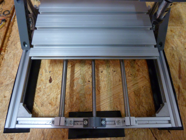
@neverdie Out of curiosity, I thought most CNC machines used ball screws. That to me looks like a lead screw.
Vera Plus running UI7 with MySensors, Sonoffs and 1-Wire devices
Visit my website for more Bits, Bytes and Ramblings from me: http://dan.bemowski.info/ -
@neverdie Out of curiosity, I thought most CNC machines used ball screws. That to me looks like a lead screw.
-
@neverdie Good, then I don't feel so bad using plain 5/16 threaded rods in my build. I would assume that there is some sort of anti backlash where it connects to the carriage though, correct? There is not a lot of play in mine to begin with, but I am using two threaded rod coupler nuts with a spring in between on mine to take up any little bit of backlash it might have.
Vera Plus running UI7 with MySensors, Sonoffs and 1-Wire devices
Visit my website for more Bits, Bytes and Ramblings from me: http://dan.bemowski.info/ -
@neverdie Good, then I don't feel so bad using plain 5/16 threaded rods in my build. I would assume that there is some sort of anti backlash where it connects to the carriage though, correct? There is not a lot of play in mine to begin with, but I am using two threaded rod coupler nuts with a spring in between on mine to take up any little bit of backlash it might have.
@dbemowsk said in CNC PCB milling:
I am using two threaded rod coupler nuts with a spring in between on mine to take up any little bit of backlash it might have.
Yes, mine has a similar spring, and I assume for the same reason.
-
For now, I've settled on this hardware for monitoring the CNC when I'm not in the garage:
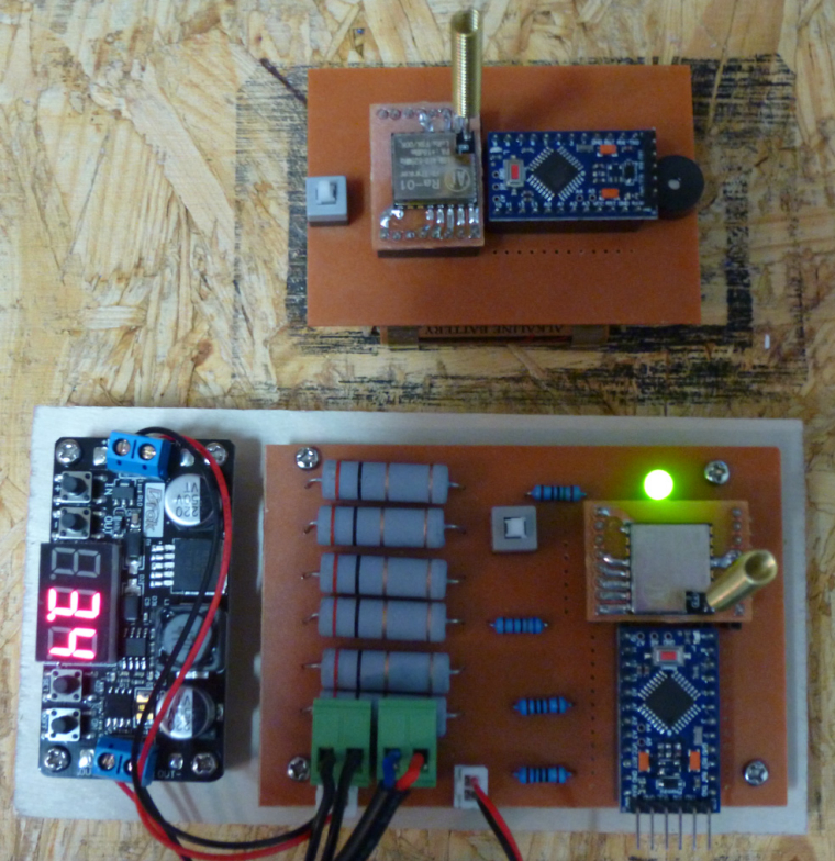
The bottom unit monitors the current that the CNC consumes to determine whether or not the CNC is active. When the CNC transitions from active to inactive, it sends a wireless signal to the battery powered node (above it in the photo), which rings a buzzer to let me know that the CNC has finished.Since my 3D printer that's on order is also 24 volts, I think there's a good chance this hardware may work with it as well. :)
-
The sorbathane helped a little, maybe, but there's still a lot of vibration. Found this video on how to dampen a 3D printer. It has some Interesting ideas on how to dampen vibrations:
https://www.youtube.com/watch?v=OnfYA5QLA84The video is aimed at Mk3 i2 owners, but I imagine similar tricks might work for a small CNC such as that discussed on this thread.