CNC PCB milling
-
@neverdie said in CNC PCB milling:
I don't know. You could try asking the seller
Thanks, I wasn't sure if you bought yours as a package deal where they had the specs on all the parts.
Your link says its an ER11A, whereas I think mine may be just an ER11.
I did find this link (http://www.cnczone.com/forums/cnc-tooling/319670-er11-type-vs-b-type.html) which states that the A should designate the style of the clamping nut. Looking at the different styles they have, it just looks like they just use different tools to tighten the nut. A looks like a standard wrench type.
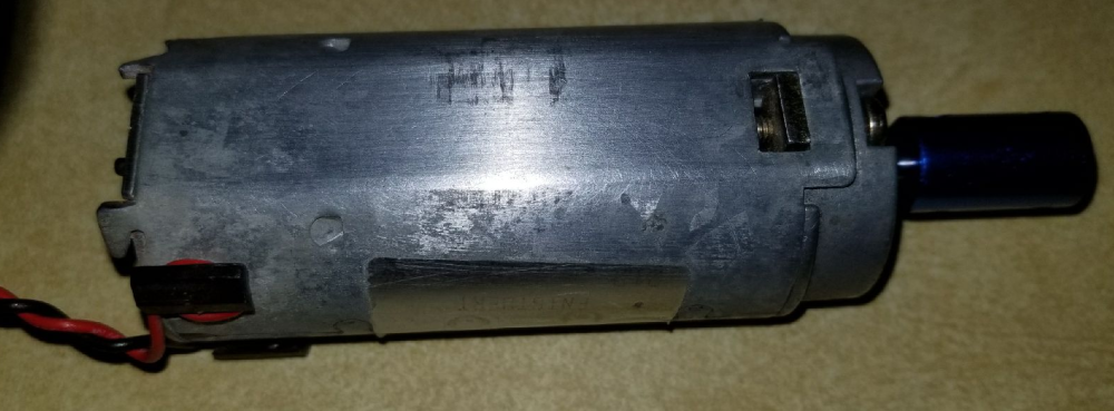
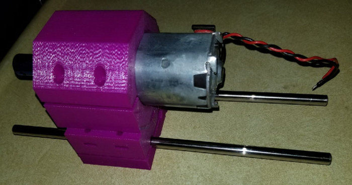
This is the only information I have on the motor that I plan on using. I googled all the numbers and couldn't find anything.
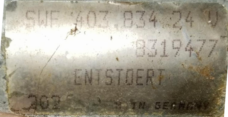
It is a German made motor, so I am assuming it is a pretty good motor. It feels like it has pretty good torque. It is one that I had in my junk parts bin. it has a 5mm D type shaft. In the pic I just have one of my 5mm to 8mm couplers on it. I think I may order that collet assembly as it sounds like it should work. It says that it uses ER11 collets anyway.
-
As it turns out, the smooth rods on my CNC are 10mm in diameter, not the more common 8mm found on 3D printers. Definitely not hardened: I can see grooves where the ball bearings have scratched into it.
Sanladerer strongly recommends using precision tolerance hardened chromed rods for 3D printers, so I can only assume the same would apply to CNC.
Since it's a relatively cheap upgrade, I may do it.
What tolerance should I get? h6? Also, what spec for surface roughness?
@neverdie said in CNC PCB milling:
Definitely not hardened: I can see grooves where the ball bearings have scratched into it.
Since it's a relatively cheap upgrade, I may do it.What tolerance should I get? h6? Also, what spec for surface roughness?
not surprised it is not hardened for the price, cheap price->cheap quality
pity is sometimes even more expensive kits cheat on this too..I would say as long as you use h6/h7 with roughness around 60 or more, so, precision hardened, chromed nice too, you should be very fine. day&night vs cheap rods which, in first place are not made for this job+precision..
-
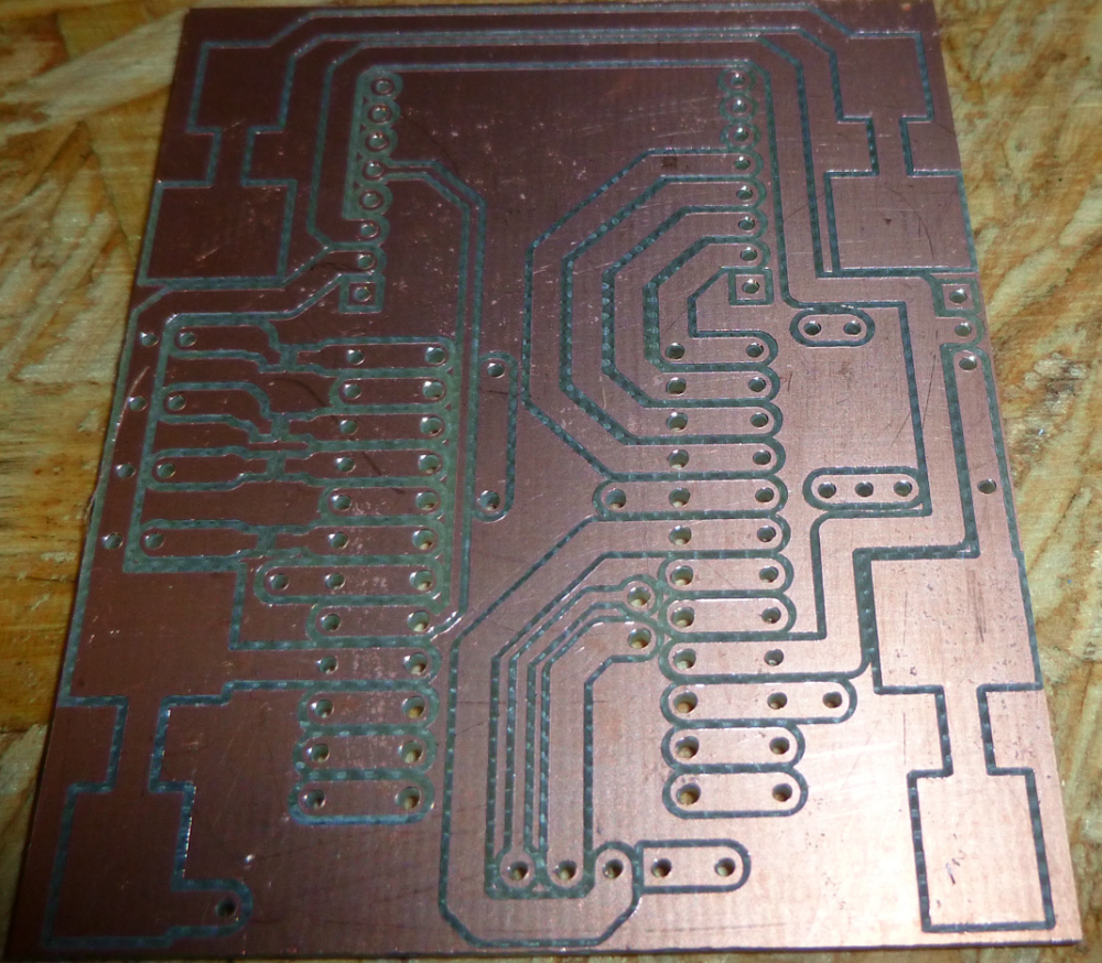
I made some enhancements to the remote used with the CNC Monitor. Among other things, it's now more compact, and the top now has a ground plane (which may help the RF):
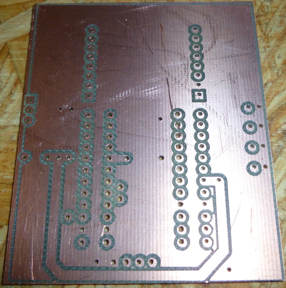
The bottom makes most of the connections and will hold the two AA batteries:
-
I made some enhancements to the remote used with the CNC Monitor. Among other things, it's now more compact, and the top now has a ground plane (which may help the RF):
The bottom makes most of the connections and will hold the two AA batteries:
@neverdie So I have an odd CNC related couple of questions. Next, when you put a bit in the chuck, do you always bury it in to the base of the bit? When you have your bit in for working on PCBs, what is the distance from the end of the chuck to the tip of the bit that you use?
Vera Plus running UI7 with MySensors, Sonoffs and 1-Wire devices
Visit my website for more Bits, Bytes and Ramblings from me: http://dan.bemowski.info/ -
@neverdie So I have an odd CNC related couple of questions. Next, when you put a bit in the chuck, do you always bury it in to the base of the bit? When you have your bit in for working on PCBs, what is the distance from the end of the chuck to the tip of the bit that you use?
-
@neverdie So I have an odd CNC related couple of questions. Next, when you put a bit in the chuck, do you always bury it in to the base of the bit? When you have your bit in for working on PCBs, what is the distance from the end of the chuck to the tip of the bit that you use?
-
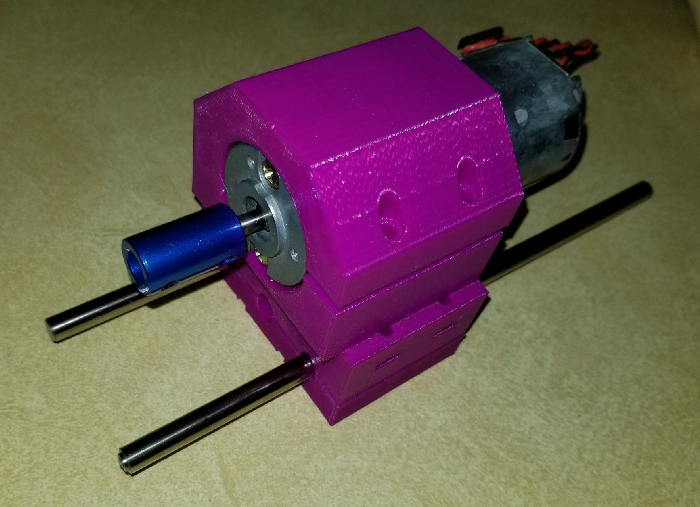
@neverdie Actually, I am working on my Z axis and am trying to gauge how long I should have my rods. They are currently 8.25 in (209.55 mm). Wondering if there would be any benefit to leaving them that long or shortening them up some more.
This is the spindle frame as I have it designed so far. The blue piece on the motor shaft is just one of the couplers that I bought for the steppers to connect the threaded rods. It is just for looks until I get the chuck.
Vera Plus running UI7 with MySensors, Sonoffs and 1-Wire devices
Visit my website for more Bits, Bytes and Ramblings from me: http://dan.bemowski.info/ -
@neverdie Actually, I am working on my Z axis and am trying to gauge how long I should have my rods. They are currently 8.25 in (209.55 mm). Wondering if there would be any benefit to leaving them that long or shortening them up some more.
This is the spindle frame as I have it designed so far. The blue piece on the motor shaft is just one of the couplers that I bought for the steppers to connect the threaded rods. It is just for looks until I get the chuck.
@dbemowsk said in CNC PCB milling:
@neverdie Actually, I am working on my Z axis and am trying to gauge how long I should have my rods. They are currently 8.25 in (209.55 mm). Wondering if there would be any benefit to leaving them that long or shortening them up some more.
In that case, what matters is whether you can raise the spindle high enough on the z-axis to remove the used bit and insert the next one. I wish my z-axis had a bit more height on it. Sometimes I have to move the spindle away from the workpiece in order to get enough clearance for a tool change. I suppose it doesn't help that I'm using a 3/4" waste board. ;)
-
@dbemowsk said in CNC PCB milling:
@neverdie Actually, I am working on my Z axis and am trying to gauge how long I should have my rods. They are currently 8.25 in (209.55 mm). Wondering if there would be any benefit to leaving them that long or shortening them up some more.
In that case, what matters is whether you can raise the spindle high enough on the z-axis to remove the used bit and insert the next one. I wish my z-axis had a bit more height on it. Sometimes I have to move the spindle away from the workpiece in order to get enough clearance for a tool change. I suppose it doesn't help that I'm using a 3/4" waste board. ;)
@neverdie said in CNC PCB milling:
I suppose it doesn't help that I'm using a 3/4" waste board.
Do you need 3/4"? Wouldn't 1/4" or 1/2" work? Do you drill in that far?
Vera Plus running UI7 with MySensors, Sonoffs and 1-Wire devices
Visit my website for more Bits, Bytes and Ramblings from me: http://dan.bemowski.info/ -
@neverdie said in CNC PCB milling:
I suppose it doesn't help that I'm using a 3/4" waste board.
Do you need 3/4"? Wouldn't 1/4" or 1/2" work? Do you drill in that far?
-
@neverdie Actually, I am working on my Z axis and am trying to gauge how long I should have my rods. They are currently 8.25 in (209.55 mm). Wondering if there would be any benefit to leaving them that long or shortening them up some more.
This is the spindle frame as I have it designed so far. The blue piece on the motor shaft is just one of the couplers that I bought for the steppers to connect the threaded rods. It is just for looks until I get the chuck.
-
@neverdie FOr starters I am trying 3D printed rod bearings. I';ll see how that goes. The beauty of designing this myself is that I can alter the design whenever I want.
-
Here is the above PCB after assembly:
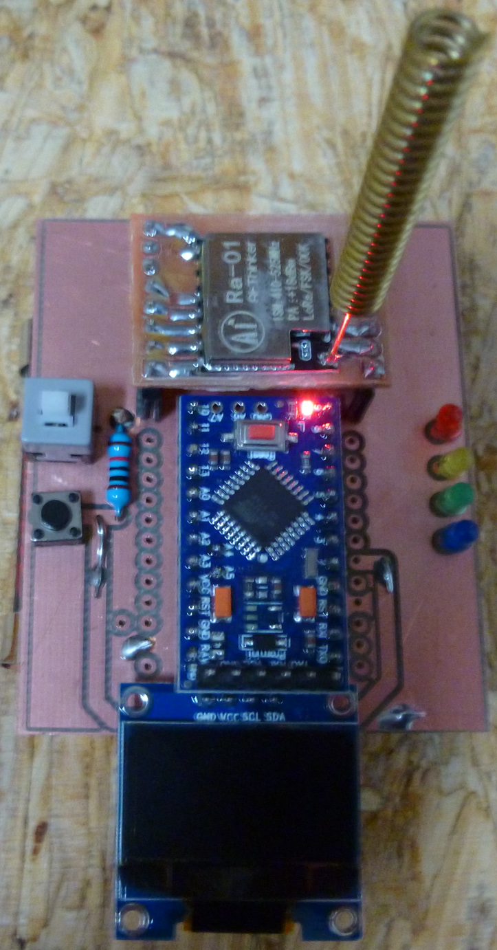
As you can see, it offers more potential functionality than the earlier version. It still has a buzzer, which is now mounted underneath the pro mini.
@neverdie Di the relocation of the buzzer increase audibility as you were seeking?
-
@neverdie FOr starters I am trying 3D printed rod bearings. I';ll see how that goes. The beauty of designing this myself is that I can alter the design whenever I want.
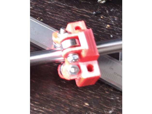
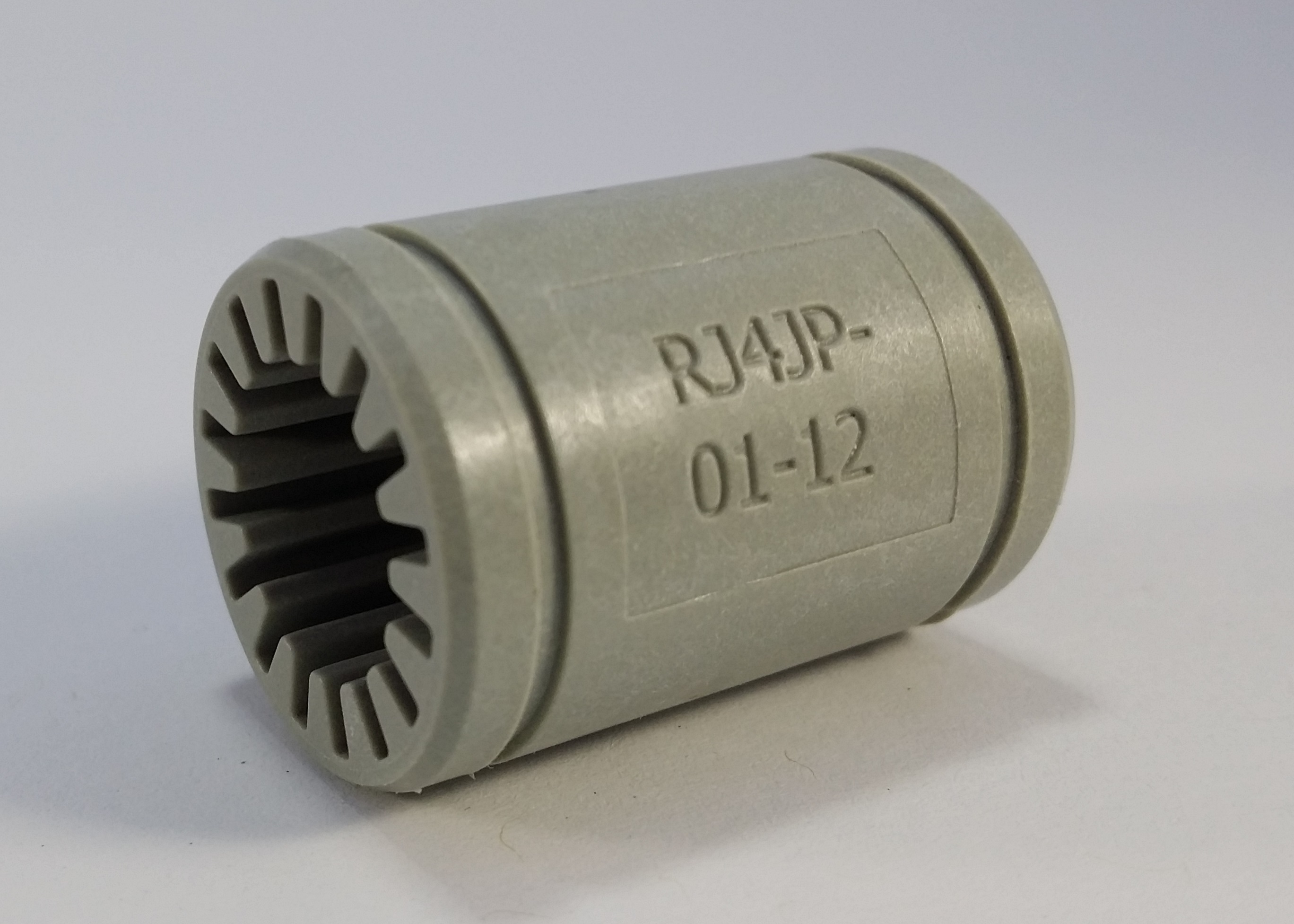
@dbemowsk said in CNC PCB milling:
I am trying 3D printed rod bearings
What are those? Is it like this?
or this?
-
@dbemowsk said in CNC PCB milling:
I am trying 3D printed rod bearings
What are those? Is it like this?
or this?
-
@neverdie I just printed them in PLA and they seem to slide pretty smoothly on the rods, but someone told me that printing them in nylon is better.
Vera Plus running UI7 with MySensors, Sonoffs and 1-Wire devices
Visit my website for more Bits, Bytes and Ramblings from me: http://dan.bemowski.info/
 mine are similar 3D printed ones