Skip to content
  • MySensors
  • OpenHardware.io
  • Categories
  • Recent
  • Tags
  • Popular
Skins
  • Light
  • Brite
  • Cerulean
  • Cosmo
  • Flatly
  • Journal
  • Litera
  • Lumen
  • Lux
  • Materia
  • Minty
  • Morph
  • Pulse
  • Sandstone
  • Simplex
  • Sketchy
  • Spacelab
  • United
  • Yeti
  • Zephyr
  • Dark
  • Cyborg
  • Darkly
  • Quartz
  • Slate
  • Solar
  • Superhero
  • Vapor

  • Default (No Skin)
  • No Skin
Collapse
Brand Logo
  1. Home
  2. General Discussion
  3. CNC PCB milling

CNC PCB milling

Scheduled Pinned Locked Moved General Discussion
933 Posts 28 Posters 539.0k Views 27 Watching
  • Oldest to Newest
  • Newest to Oldest
  • Most Votes
Reply
  • Reply as topic
Log in to reply
This topic has been deleted. Only users with topic management privileges can see it.
  • N Offline
    N Offline
    NeverDie
    Hero Member
    wrote on last edited by NeverDie
    #558

    As it turns out, the smooth rods on my CNC are 10mm in diameter, not the more common 8mm found on 3D printers. Definitely not hardened: I can see grooves where the ball bearings have scratched into it.

    Sanladerer strongly recommends using precision tolerance hardened chromed rods for 3D printers, so I can only assume the same would apply to CNC.

    Since it's a relatively cheap upgrade, I may do it.

    What tolerance should I get? h6? Also, what spec for surface roughness?

    S 1 Reply Last reply
    0
    • N NeverDie

      As it turns out, the smooth rods on my CNC are 10mm in diameter, not the more common 8mm found on 3D printers. Definitely not hardened: I can see grooves where the ball bearings have scratched into it.

      Sanladerer strongly recommends using precision tolerance hardened chromed rods for 3D printers, so I can only assume the same would apply to CNC.

      Since it's a relatively cheap upgrade, I may do it.

      What tolerance should I get? h6? Also, what spec for surface roughness?

      S Offline
      S Offline
      scalz
      Hardware Contributor
      wrote on last edited by scalz
      #559

      @neverdie said in CNC PCB milling:

      Definitely not hardened: I can see grooves where the ball bearings have scratched into it.
      Since it's a relatively cheap upgrade, I may do it.

      What tolerance should I get? h6? Also, what spec for surface roughness?

      not surprised it is not hardened for the price, cheap price->cheap quality
      pity is sometimes even more expensive kits cheat on this too..

      I would say as long as you use h6/h7 with roughness around 60 or more, so, precision hardened, chromed nice too, you should be very fine. day&night vs cheap rods which, in first place are not made for this job+precision..

      1 Reply Last reply
      1
      • N Offline
        N Offline
        NeverDie
        Hero Member
        wrote on last edited by
        #560

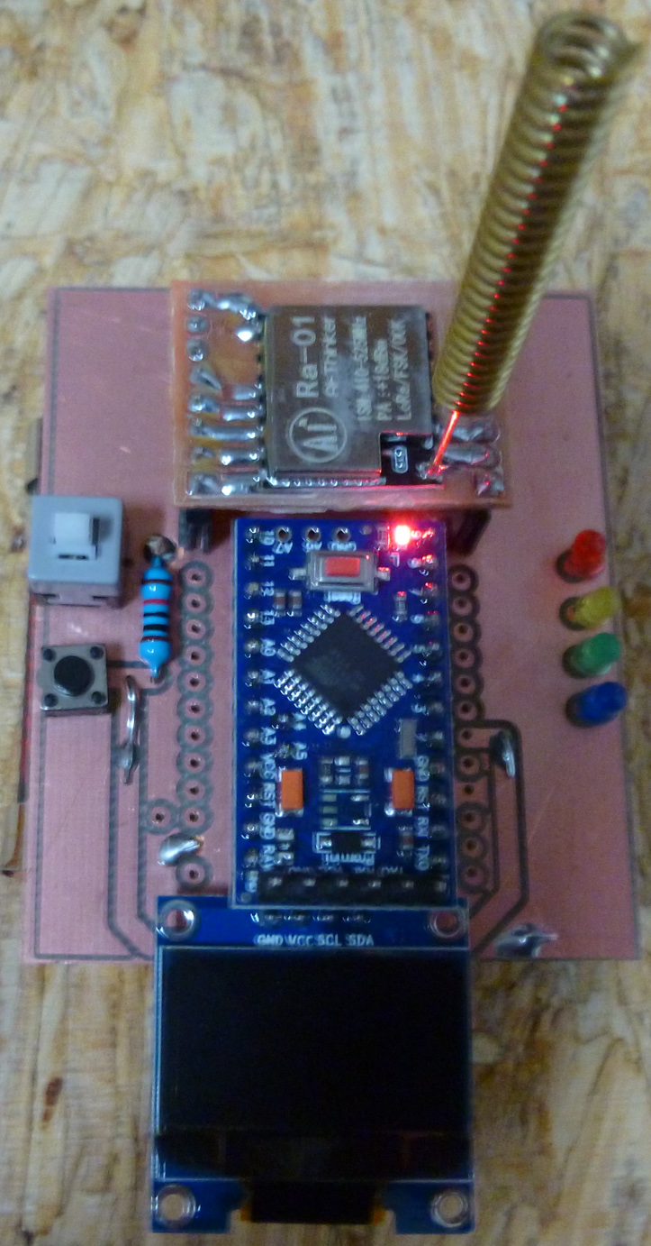
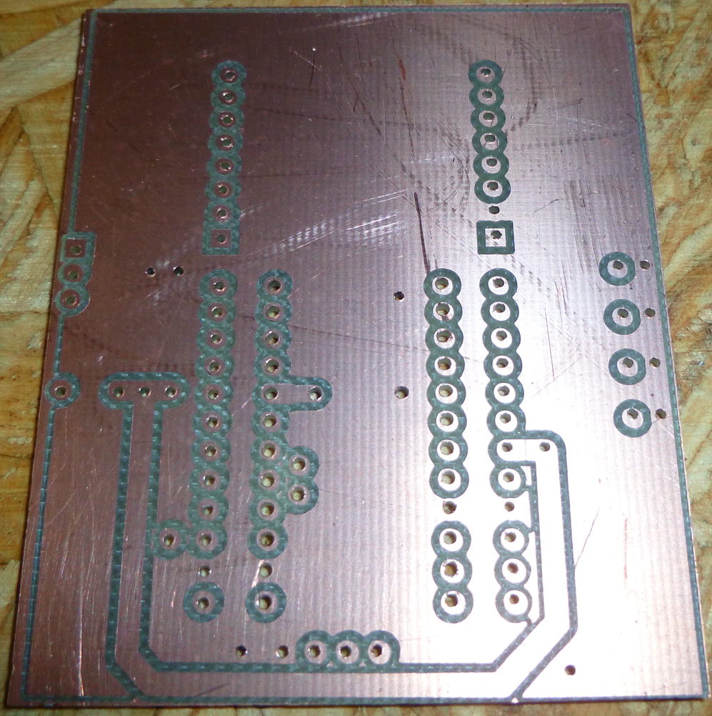
        I made some enhancements to the remote used with the CNC Monitor. Among other things, it's now more compact, and the top now has a ground plane (which may help the RF):
        0_1519358557167_top_remote.jpg

        The bottom makes most of the connections and will hold the two AA batteries:
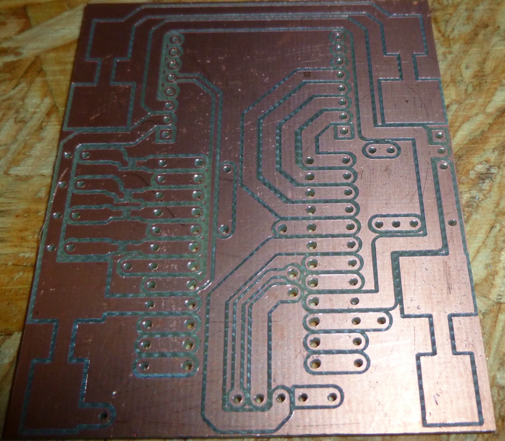
        0_1519358646476_bottom_remote.jpg

        D 1 Reply Last reply
        1
        • N NeverDie

          I made some enhancements to the remote used with the CNC Monitor. Among other things, it's now more compact, and the top now has a ground plane (which may help the RF):
          0_1519358557167_top_remote.jpg

          The bottom makes most of the connections and will hold the two AA batteries:
          0_1519358646476_bottom_remote.jpg

          D Offline
          D Offline
          dbemowsk
          wrote on last edited by
          #561

          @neverdie So I have an odd CNC related couple of questions. Next, when you put a bit in the chuck, do you always bury it in to the base of the bit? When you have your bit in for working on PCBs, what is the distance from the end of the chuck to the tip of the bit that you use?

          Vera Plus running UI7 with MySensors, Sonoffs and 1-Wire devices
          Visit my website for more Bits, Bytes and Ramblings from me: http://dan.bemowski.info/

          N 2 Replies Last reply
          0
          • D dbemowsk

            @neverdie So I have an odd CNC related couple of questions. Next, when you put a bit in the chuck, do you always bury it in to the base of the bit? When you have your bit in for working on PCBs, what is the distance from the end of the chuck to the tip of the bit that you use?

            N Offline
            N Offline
            NeverDie
            Hero Member
            wrote on last edited by
            #562

            @dbemowsk Is this for calculating deflection?

            D 1 Reply Last reply
            0
            • D dbemowsk

              @neverdie So I have an odd CNC related couple of questions. Next, when you put a bit in the chuck, do you always bury it in to the base of the bit? When you have your bit in for working on PCBs, what is the distance from the end of the chuck to the tip of the bit that you use?

              N Offline
              N Offline
              NeverDie
              Hero Member
              wrote on last edited by
              #563

              @dbemowsk I haven't been very consistent, but I'd say roughly 7/8 inch.

              1 Reply Last reply
              0
              • N NeverDie

                @dbemowsk Is this for calculating deflection?

                D Offline
                D Offline
                dbemowsk
                wrote on last edited by
                #564

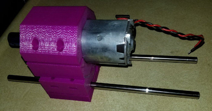
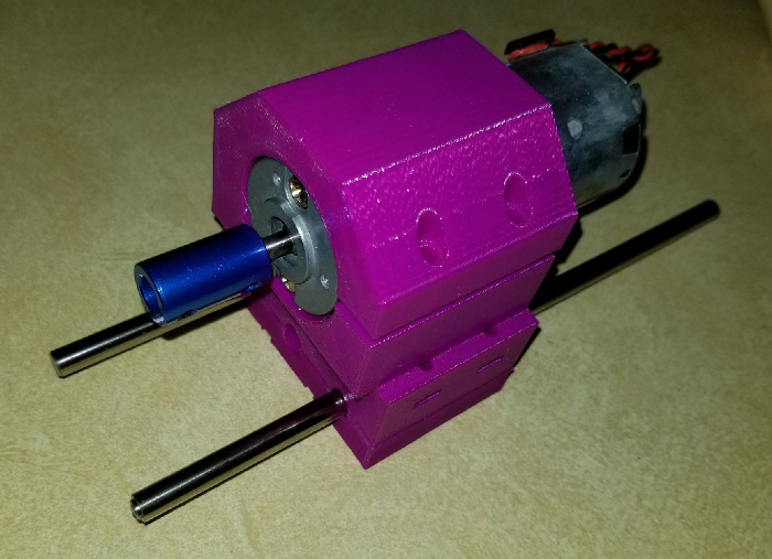
                @neverdie Actually, I am working on my Z axis and am trying to gauge how long I should have my rods. They are currently 8.25 in (209.55 mm). Wondering if there would be any benefit to leaving them that long or shortening them up some more.

                This is the spindle frame as I have it designed so far. The blue piece on the motor shaft is just one of the couplers that I bought for the steppers to connect the threaded rods. It is just for looks until I get the chuck.
                0_1519360970346_8d563b7a-2596-4409-84d9-fac1fc5d0cf8-image.png
                0_1519360983477_1630f7d1-10f4-49e8-bcdd-ab061f63cc6f-image.png

                Vera Plus running UI7 with MySensors, Sonoffs and 1-Wire devices
                Visit my website for more Bits, Bytes and Ramblings from me: http://dan.bemowski.info/

                N 2 Replies Last reply
                0
                • D dbemowsk

                  @neverdie Actually, I am working on my Z axis and am trying to gauge how long I should have my rods. They are currently 8.25 in (209.55 mm). Wondering if there would be any benefit to leaving them that long or shortening them up some more.

                  This is the spindle frame as I have it designed so far. The blue piece on the motor shaft is just one of the couplers that I bought for the steppers to connect the threaded rods. It is just for looks until I get the chuck.
                  0_1519360970346_8d563b7a-2596-4409-84d9-fac1fc5d0cf8-image.png
                  0_1519360983477_1630f7d1-10f4-49e8-bcdd-ab061f63cc6f-image.png

                  N Offline
                  N Offline
                  NeverDie
                  Hero Member
                  wrote on last edited by NeverDie
                  #565

                  @dbemowsk said in CNC PCB milling:

                  @neverdie Actually, I am working on my Z axis and am trying to gauge how long I should have my rods. They are currently 8.25 in (209.55 mm). Wondering if there would be any benefit to leaving them that long or shortening them up some more.

                  In that case, what matters is whether you can raise the spindle high enough on the z-axis to remove the used bit and insert the next one. I wish my z-axis had a bit more height on it. Sometimes I have to move the spindle away from the workpiece in order to get enough clearance for a tool change. I suppose it doesn't help that I'm using a 3/4" waste board. ;)

                  D 1 Reply Last reply
                  0
                  • N NeverDie

                    @dbemowsk said in CNC PCB milling:

                    @neverdie Actually, I am working on my Z axis and am trying to gauge how long I should have my rods. They are currently 8.25 in (209.55 mm). Wondering if there would be any benefit to leaving them that long or shortening them up some more.

                    In that case, what matters is whether you can raise the spindle high enough on the z-axis to remove the used bit and insert the next one. I wish my z-axis had a bit more height on it. Sometimes I have to move the spindle away from the workpiece in order to get enough clearance for a tool change. I suppose it doesn't help that I'm using a 3/4" waste board. ;)

                    D Offline
                    D Offline
                    dbemowsk
                    wrote on last edited by
                    #566

                    @neverdie said in CNC PCB milling:

                    I suppose it doesn't help that I'm using a 3/4" waste board.

                    Do you need 3/4"? Wouldn't 1/4" or 1/2" work? Do you drill in that far?

                    Vera Plus running UI7 with MySensors, Sonoffs and 1-Wire devices
                    Visit my website for more Bits, Bytes and Ramblings from me: http://dan.bemowski.info/

                    N 1 Reply Last reply
                    0
                    • D dbemowsk

                      @neverdie said in CNC PCB milling:

                      I suppose it doesn't help that I'm using a 3/4" waste board.

                      Do you need 3/4"? Wouldn't 1/4" or 1/2" work? Do you drill in that far?

                      N Offline
                      N Offline
                      NeverDie
                      Hero Member
                      wrote on last edited by
                      #567

                      @dbemowsk 1/2" is probably ideal for my particular setup. 3/4" is simply what I tried first. 1/4" might work, but with less margin for error.

                      1 Reply Last reply
                      0
                      • D dbemowsk

                        @neverdie Actually, I am working on my Z axis and am trying to gauge how long I should have my rods. They are currently 8.25 in (209.55 mm). Wondering if there would be any benefit to leaving them that long or shortening them up some more.

                        This is the spindle frame as I have it designed so far. The blue piece on the motor shaft is just one of the couplers that I bought for the steppers to connect the threaded rods. It is just for looks until I get the chuck.
                        0_1519360970346_8d563b7a-2596-4409-84d9-fac1fc5d0cf8-image.png
                        0_1519360983477_1630f7d1-10f4-49e8-bcdd-ab061f63cc6f-image.png

                        N Offline
                        N Offline
                        NeverDie
                        Hero Member
                        wrote on last edited by
                        #568

                        @dbemowsk Shouldn't you have some linear ball bearings gripping those z-axis rods?

                        D 1 Reply Last reply
                        0
                        • N Offline
                          N Offline
                          NeverDie
                          Hero Member
                          wrote on last edited by NeverDie
                          #569

                          Here is the above PCB after assembly:
                          0_1519407571095_assembled.jpg

                          As you can see, it offers more potential functionality than the earlier version. It still has a buzzer, which is now mounted underneath the pro mini.

                          zboblamontZ 1 Reply Last reply
                          0
                          • N NeverDie

                            @dbemowsk Shouldn't you have some linear ball bearings gripping those z-axis rods?

                            D Offline
                            D Offline
                            dbemowsk
                            wrote on last edited by
                            #570

                            @neverdie FOr starters I am trying 3D printed rod bearings. I';ll see how that goes. The beauty of designing this myself is that I can alter the design whenever I want.

                            Vera Plus running UI7 with MySensors, Sonoffs and 1-Wire devices
                            Visit my website for more Bits, Bytes and Ramblings from me: http://dan.bemowski.info/

                            N 1 Reply Last reply
                            0
                            • N NeverDie

                              Here is the above PCB after assembly:
                              0_1519407571095_assembled.jpg

                              As you can see, it offers more potential functionality than the earlier version. It still has a buzzer, which is now mounted underneath the pro mini.

                              zboblamontZ Offline
                              zboblamontZ Offline
                              zboblamont
                              wrote on last edited by
                              #571

                              @neverdie Di the relocation of the buzzer increase audibility as you were seeking?

                              1 Reply Last reply
                              0
                              • D dbemowsk

                                @neverdie FOr starters I am trying 3D printed rod bearings. I';ll see how that goes. The beauty of designing this myself is that I can alter the design whenever I want.

                                N Offline
                                N Offline
                                NeverDie
                                Hero Member
                                wrote on last edited by NeverDie
                                #572

                                @dbemowsk said in CNC PCB milling:

                                I am trying 3D printed rod bearings

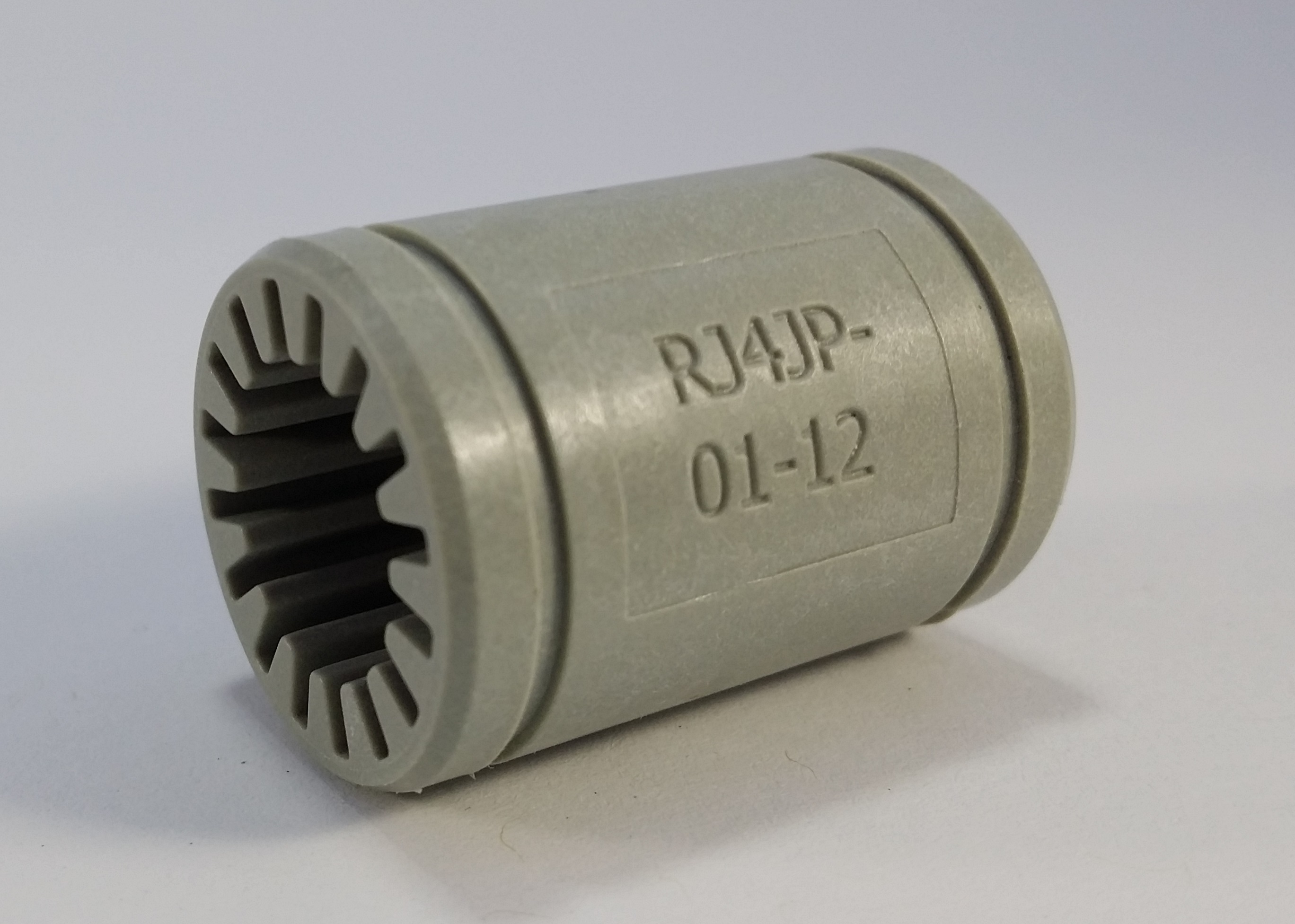
                                What are those? Is it like this?
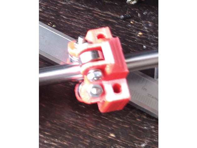
                                alt text
                                or this?
                                alt text

                                D 1 Reply Last reply
                                0
                                • N NeverDie

                                  @dbemowsk said in CNC PCB milling:

                                  I am trying 3D printed rod bearings

                                  What are those? Is it like this?
                                  alt text
                                  or this?
                                  alt text

                                  D Offline
                                  D Offline
                                  dbemowsk
                                  wrote on last edited by dbemowsk
                                  #573

                                  @neverdie these are similar linear bearings that you can buy mine are similar 3D printed ones

                                  Vera Plus running UI7 with MySensors, Sonoffs and 1-Wire devices
                                  Visit my website for more Bits, Bytes and Ramblings from me: http://dan.bemowski.info/

                                  N 1 Reply Last reply
                                  0
                                  • D dbemowsk

                                    @neverdie these are similar linear bearings that you can buy mine are similar 3D printed ones

                                    N Offline
                                    N Offline
                                    NeverDie
                                    Hero Member
                                    wrote on last edited by
                                    #574

                                    @dbemowsk what kind of material?

                                    D 1 Reply Last reply
                                    0
                                    • N NeverDie

                                      @dbemowsk what kind of material?

                                      D Offline
                                      D Offline
                                      dbemowsk
                                      wrote on last edited by
                                      #575

                                      @neverdie I just printed them in PLA and they seem to slide pretty smoothly on the rods, but someone told me that printing them in nylon is better.

                                      Vera Plus running UI7 with MySensors, Sonoffs and 1-Wire devices
                                      Visit my website for more Bits, Bytes and Ramblings from me: http://dan.bemowski.info/

                                      N 1 Reply Last reply
                                      0
                                      • D dbemowsk

                                        @neverdie I just printed them in PLA and they seem to slide pretty smoothly on the rods, but someone told me that printing them in nylon is better.

                                        N Offline
                                        N Offline
                                        NeverDie
                                        Hero Member
                                        wrote on last edited by NeverDie
                                        #576

                                        @dbemowsk said in CNC PCB milling:

                                        printing them in nylon is better.

                                        It would seem so: http://www.craftechind.com/top-5-materials-for-plastic-bearings-used-on-metal-surfaces/

                                        If you had a multi-filament printer, I wonder if you could print the nylon bearing within another plastic piece (e.g. the part that holds the spindle to the z-axis)? That would would be pretty cool and would also save assembly time.


                                        D 1 Reply Last reply
                                        0
                                        • N NeverDie

                                          @dbemowsk said in CNC PCB milling:

                                          printing them in nylon is better.

                                          It would seem so: http://www.craftechind.com/top-5-materials-for-plastic-bearings-used-on-metal-surfaces/

                                          If you had a multi-filament printer, I wonder if you could print the nylon bearing within another plastic piece (e.g. the part that holds the spindle to the z-axis)? That would would be pretty cool and would also save assembly time.

                                          D Offline
                                          D Offline
                                          dbemowsk
                                          wrote on last edited by
                                          #577

                                          @neverdie the way i have it designed, the printed bearings get sandwiched by a rear plate that holds the bearings and coupler nut that goes on the threaded rod to drive the assembly up and down.

                                          Vera Plus running UI7 with MySensors, Sonoffs and 1-Wire devices
                                          Visit my website for more Bits, Bytes and Ramblings from me: http://dan.bemowski.info/

                                          1 Reply Last reply
                                          1

                                          Hello! It looks like you're interested in this conversation, but you don't have an account yet.

                                          Getting fed up of having to scroll through the same posts each visit? When you register for an account, you'll always come back to exactly where you were before, and choose to be notified of new replies (either via email, or push notification). You'll also be able to save bookmarks and upvote posts to show your appreciation to other community members.

                                          With your input, this post could be even better 💗

                                          Register Login
                                          Reply
                                          • Reply as topic
                                          Log in to reply
                                          • Oldest to Newest
                                          • Newest to Oldest
                                          • Most Votes


                                          9

                                          Online

                                          12.0k

                                          Users

                                          11.2k

                                          Topics

                                          113.4k

                                          Posts


                                          Copyright 2025 TBD   |   Forum Guidelines   |   Privacy Policy   |   Terms of Service
                                          • Login

                                          • Don't have an account? Register

                                          • Login or register to search.
                                          • First post
                                            Last post
                                          0
                                          • MySensors
                                          • OpenHardware.io
                                          • Categories
                                          • Recent
                                          • Tags
                                          • Popular