CNC PCB milling
-
@neverdie I guess some backlash being present. Is the brushless heavier than the other one?
The width of the cut is proportional to engraving bit tip size, depth of cut, tip angle, the spindle itself should be irrelevant except runout, of course, but you will hear the runout long before you see it, a 0.1mm of runout will make a hell lot of noise and rattling.
For greater rpms er8 is better than er11, my 60k rpm has er8 the 24k have er11.
Try to find the highers resonance pole rpm, turn the rpm to max, slowly decrease it while listening carefully, take a note when it's quieter, use the highest rpm that runs quietly. This setting unfortunately changes with every tool change, sometimes you won't have a good enough rpm resonant pole so you take out the bit, nut and collet and reassemble. By turning them you change the invisible runout a bit and you get another system state. On my spindle every 1/10-1/15 tool changes results in heavy resonance and I must proceed as above.@executivul Cool! Here's my first attempt at that, and it's already producing a visibly different result:
As to which spindle is heavier, I don't know. The next time I demount the brush spindle, I'll weigh it and let you know.
Thanks!
-
This guy developed his own method for balancing the high speed motors used on his quadcopter. I can't help but think that maybe something similar could be done on a CNC spindle.
In depth video how to balance brushless motors using a vibration meter and tape - Ontaerial – 25:35
— Yuri Retro -
And these guys have the same idea, but they instead use a laser to visualize the magnitude of the vibration:
Flite Test - Laser Balancing Props - FLITE TIP – 07:11
— FliteTest -
And these guys have the same idea, but they instead use a laser to visualize the magnitude of the vibration:
Flite Test - Laser Balancing Props - FLITE TIP – 07:11
— FliteTest@neverdie knowing the vfd has a speed input I guess I could wire a simple arduino with a mic. Take note of the sound level and get it calibtared in no time, at the push of a button, but that project is far away, I have other things on my mind for the next few months.
-
hello everyone,
what is the current status with the quality, fine traces and result stability?
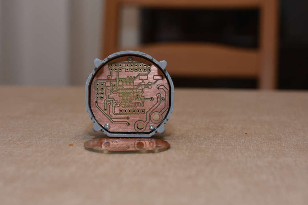
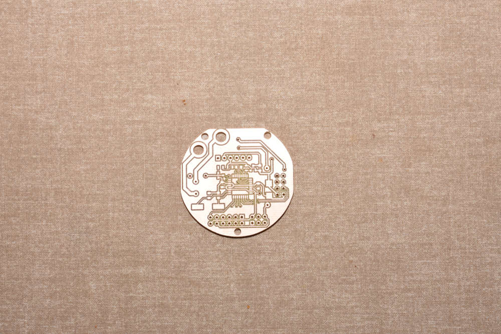
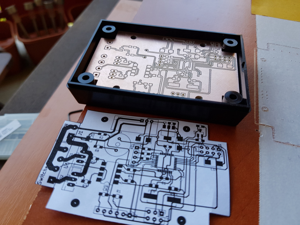
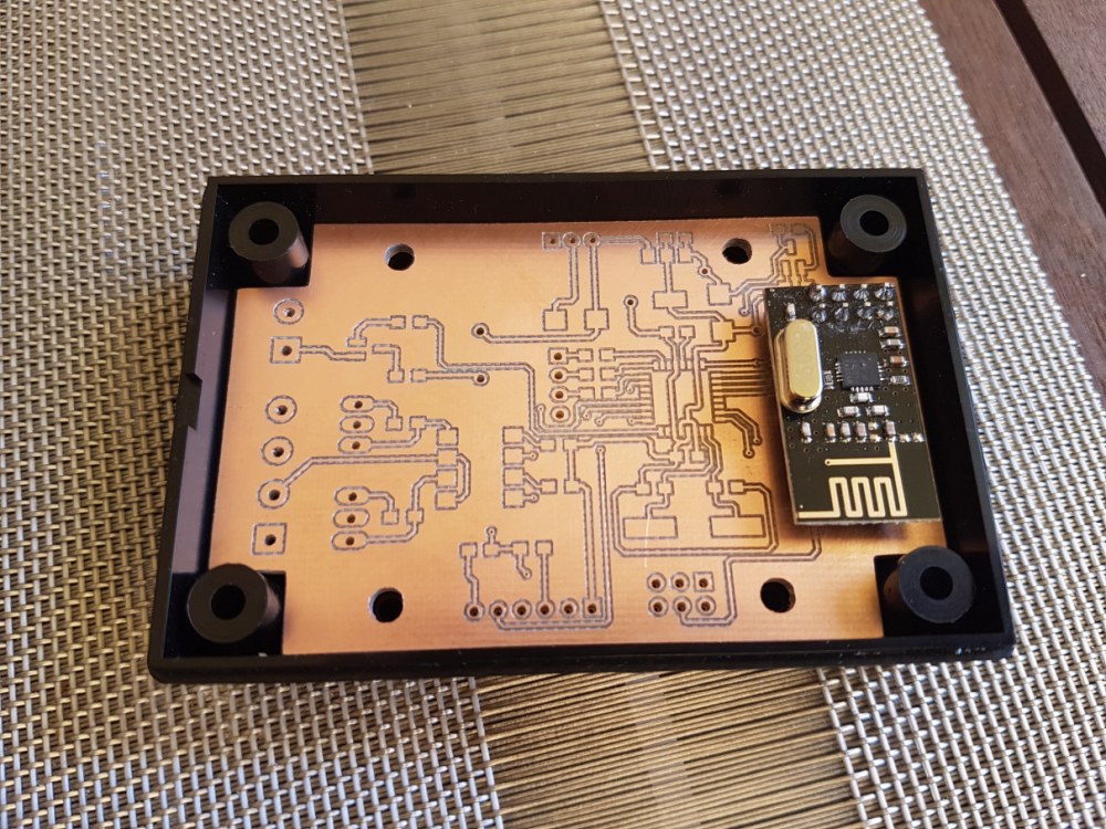
after a long absence I finally had some time to finish my new board and prototype it.
I don't have those issues that appearing for some of you, the result is pretty nice, the milling quality is the same across the whole board.
in this design the thinnest traces were 15mils, and the smallest vias were 0.8mm with 0.3mm drilled holes.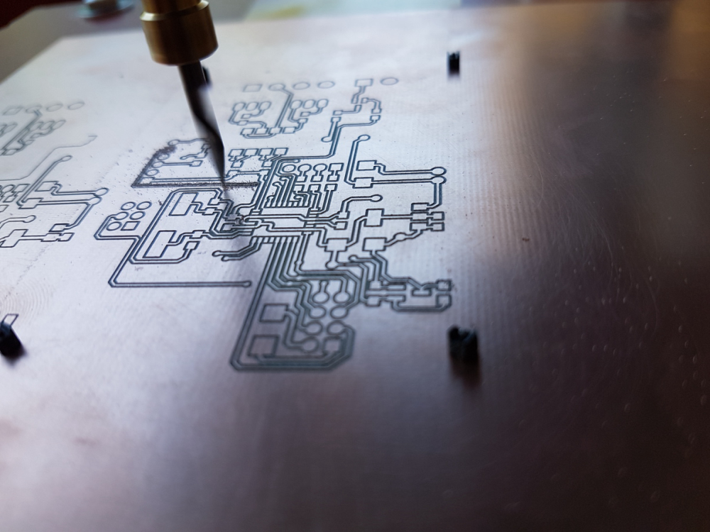
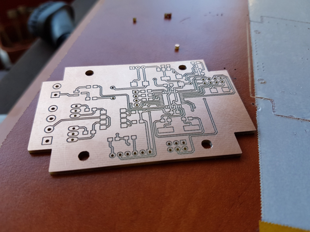
just for reference, please see my relevant configuration options detailed below:
tools
- cnc: cnc2418
- carving: 2001 bit (20 degree, 0.1mm end)
- mounting holes and outline milling: 0.8mm endmill
config
- isolation routing: tool dia: 0.1176326981mm; width (# passes): 2; pass overlap: 0.05mm; cut-z: -0.05mm; feed rate: 200
- milling: tool dia: 0.8mm; cut-z: -1.75mm; feed rate: 170; depth / pass: 0.3mm
- drilling: feed rate: 120
software:
- flatcam
- bcnc (also for the autoleveling)
-
Hi Andrew,
Since you ask about status, here's mine: I've now replaced all the aluminum smooth rods that came with my 2418 kit with chromed hardened steel ones which, it turned out, had about 0.04mm larger diameter. The result has been much less apparent vibration. I also upgraded the spindle to a higher rpm motor. I don't as yet have any quantified numbers to know whether the combination of doing all that has made any tangible improvement or not.
-
hello everyone,
what is the current status with the quality, fine traces and result stability?
after a long absence I finally had some time to finish my new board and prototype it.
I don't have those issues that appearing for some of you, the result is pretty nice, the milling quality is the same across the whole board.
in this design the thinnest traces were 15mils, and the smallest vias were 0.8mm with 0.3mm drilled holes.just for reference, please see my relevant configuration options detailed below:
tools
- cnc: cnc2418
- carving: 2001 bit (20 degree, 0.1mm end)
- mounting holes and outline milling: 0.8mm endmill
config
- isolation routing: tool dia: 0.1176326981mm; width (# passes): 2; pass overlap: 0.05mm; cut-z: -0.05mm; feed rate: 200
- milling: tool dia: 0.8mm; cut-z: -1.75mm; feed rate: 170; depth / pass: 0.3mm
- drilling: feed rate: 120
software:
- flatcam
- bcnc (also for the autoleveling)
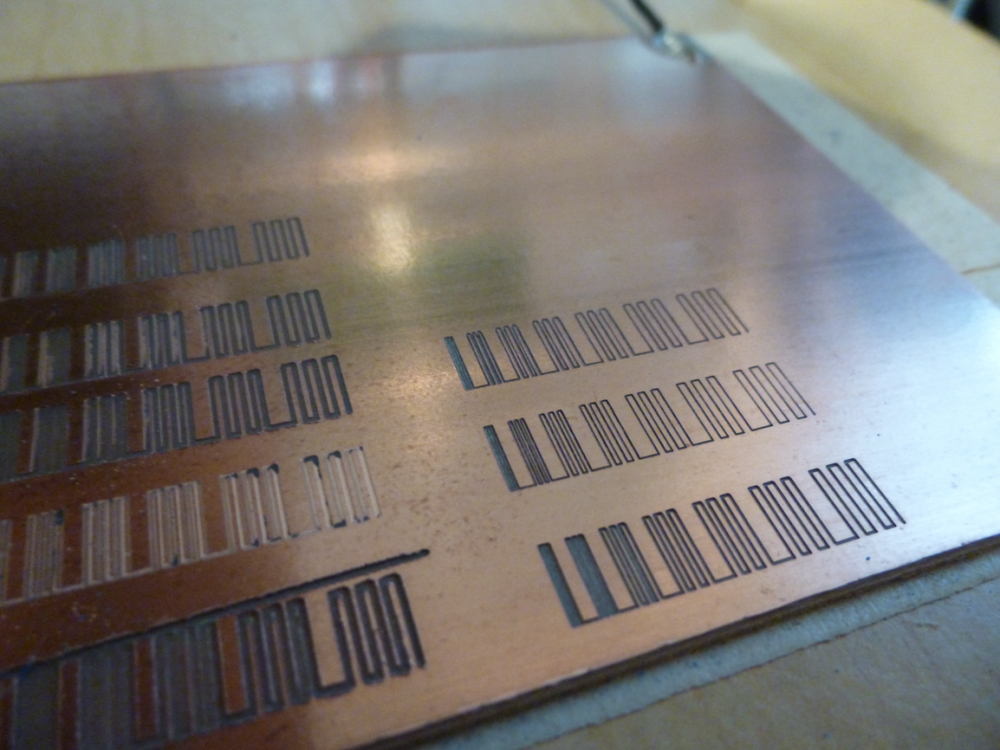
@andrew I ran @executivul 's diagnostic with my new setup:
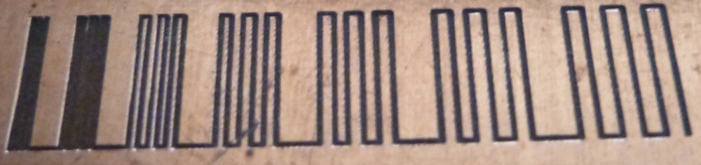
Starting with 0.1mm, the trace width's increase by 0.1mm in each block.@executivul's g-code specified the feedrate at 1400.
So, yeah, 15mil looks like it would be achievable, even at that faster feedrate. On the otherhand, the woodpecker setting limits x and y to 200mm speeds, so I guess (?) the speed never actually gets beyond those limits anyway.
The next upgrade after this will be switching over to trinamic drivers, which may (?) be able to drive things a bit faster. That will likely require dropping woodpecker and switching over to marlin firmware so as to get the most out of the trinamic drivers.
-
@andrew I ran @executivul 's diagnostic with my new setup:
Starting with 0.1mm, the trace width's increase by 0.1mm in each block.@executivul's g-code specified the feedrate at 1400.
So, yeah, 15mil looks like it would be achievable, even at that faster feedrate. On the otherhand, the woodpecker setting limits x and y to 200mm speeds, so I guess (?) the speed never actually gets beyond those limits anyway.
The next upgrade after this will be switching over to trinamic drivers, which may (?) be able to drive things a bit faster. That will likely require dropping woodpecker and switching over to marlin firmware so as to get the most out of the trinamic drivers.
@neverdie what was the cost for the overall upgrade?
for me the 10 mil traces also worked with the default sw/hw configuration.
did you change any parameter in the grbl firmware? 1400 feedrate is very nice, much faster than mine, however I did not use higher rates than 200 so far.
your steppers are still the same? is it ok for the high feedrate without any issue?
-
@andrew I ran @executivul 's diagnostic with my new setup:
Starting with 0.1mm, the trace width's increase by 0.1mm in each block.@executivul's g-code specified the feedrate at 1400.
So, yeah, 15mil looks like it would be achievable, even at that faster feedrate. On the otherhand, the woodpecker setting limits x and y to 200mm speeds, so I guess (?) the speed never actually gets beyond those limits anyway.
The next upgrade after this will be switching over to trinamic drivers, which may (?) be able to drive things a bit faster. That will likely require dropping woodpecker and switching over to marlin firmware so as to get the most out of the trinamic drivers.
@neverdie said in CNC PCB milling:
On the otherhand, the woodpecker setting limits x and y to 200mm speeds, so I guess (?) the speed never actually gets beyond those limits anyway. -
@neverdie said in CNC PCB milling:
On the otherhand, the woodpecker setting limits x and y to 200mm speeds, so I guess (?) the speed never actually gets beyond those limits anyway.@neverdie the controller does not limit it, but the firmware settings. however, based on my default settings the feedrate is limited (by config) to 800. check your $110, $111, and $112 config options.
https://github.com/gnea/grbl/wiki/Grbl-v1.1-Configuration#110-111-and-112--xyz-max-rate-mmminyou are free to override this configuration with a different value, so you can try 1400 in the grbl firmware settings, which will cause real 1400 feed rate in case of you test G code.
the questions is that how the steppers/spindle could handle this. -
@neverdie what was the cost for the overall upgrade?
for me the 10 mil traces also worked with the default sw/hw configuration.
did you change any parameter in the grbl firmware? 1400 feedrate is very nice, much faster than mine, however I did not use higher rates than 200 so far.
your steppers are still the same? is it ok for the high feedrate without any issue?
@andrew said in CNC PCB milling:
what was the cost for the overall upgrade?
The spindle I'm currently using cost $34:
https://www.aliexpress.com/item/BEST-300W-Mini-Spindle-motor-DC12-48V-ER11-12000rpm-Engraving-milling-grind-air-cooling-spindle-motor/32799767627.html?spm=a2g0s.9042311.0.0.27424c4dQrDJU8I power it with a separate, adjustable power supply, since it can go to 48v.
I had to 3D print an adapter for the new spindle to fit onto the 2418. Cottingbear has one on thingiverse. Aside from the plastic filament needed for the print (maybe $2 worth), it requires just 4 short linear bearings and a lead nut.
The 6 chromed steel smooth rods cost around $20-30 in total, including e-packet delivery.
My feeling is that the steel rods are a worthwhile and very easy upgrade, even though I don't have data to prove they make any difference. Not sure yet whether the new spindle will eventually produce better results or not, although it does run quieter, which is nice. :)
The yet to be used trinamic drivers cost $42.50: https://www.aliexpress.com/item/5X-MKS-TMC2130-V1-1-For-SPI-Function-Stepstick-Stepper-Motor-Driver-With-Heat-Sink-5PCS/32850180071.html?spm=a2g0s.9042311.0.0.27424c4ddQiQqN
I got a couple extra in case I accidentally burn one or two of them out. I'll be plugging them into a RAMPS board, which is cheap, and which, as an arduino Mega 2560 shield, will replace the woodpecker board. -
@dbemowsk said in CNC PCB milling:
@neverdie Can you run a stock GRBL build on RAMPS?
I don't know. I'm planning to use Marlin, which supposedly can exploit at least some of the TMC2130 driver's special features.
After I get all that working, then I may upgrade to higher torque stepper drivers, still NEMA 17 though, as the trinamics can support more current than the A4988's that are on the woodpecker.
-
I found out that I can buy precision rods and matching linear bearings directly from https://us.misumi-ec.com. Because of the tighter fit, this would, I'm guessing, reduce the deflection on the x-axis.
-
By checking this discussion i have found a project online called: pcb cyclone factory. I am novice. What do you think about it ?
https://reprap.org/wiki/Cyclone_PCB_Factory -
By checking this discussion i have found a project online called: pcb cyclone factory. I am novice. What do you think about it ?
https://reprap.org/wiki/Cyclone_PCB_Factory@jeremushka Looks like it might be kinda shakey. Vibration is a notable enemy.
-
@jeremushka Looks like it might be kinda shakey. Vibration is a notable enemy.
@neverdie yes you are right. I have found a more complete machine. Seems we can use not only for milling. Can be interesting as well. What do you think ?
-
Looks no worse than what I have .
-
I would like to create pcb's with a 0.5mm pitch as a target and I have tried to follow this thread for hints. Have you @andrew, @NeverDie or @executivul been able to get that done with the milling method?
Then one of the problems with the 2418 that @NeverDie seemed to have was that the machine itself was not stable enough. Do you think that the cheap 3018 work better? For example
https://www.aliexpress.com/store/product/CNC-3018-laser-options-with-ER11-diy-cnc-engraving-machine-Pcb-Milling-Machine-Wood-Carving-machine/424291_32806004900.html
or
https://www.amazon.com/Control-Machine-Engraver-Controller-Extension/dp/B07KYH6BTK/ref=sr_1_6?ie=UTF8&qid=1548751586&sr=8-6&keywords=cnc+3018 -
I would like to create pcb's with a 0.5mm pitch as a target and I have tried to follow this thread for hints. Have you @andrew, @NeverDie or @executivul been able to get that done with the milling method?
Then one of the problems with the 2418 that @NeverDie seemed to have was that the machine itself was not stable enough. Do you think that the cheap 3018 work better? For example
https://www.aliexpress.com/store/product/CNC-3018-laser-options-with-ER11-diy-cnc-engraving-machine-Pcb-Milling-Machine-Wood-Carving-machine/424291_32806004900.html
or
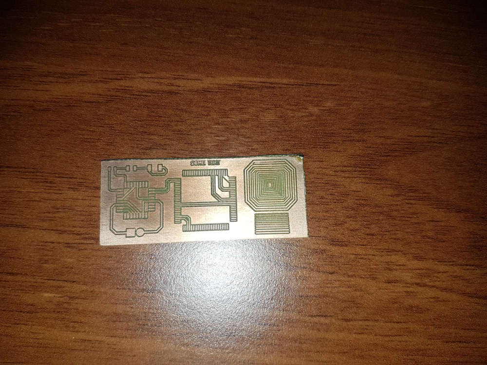
https://www.amazon.com/Control-Machine-Engraver-Controller-Extension/dp/B07KYH6BTK/ref=sr_1_6?ie=UTF8&qid=1548751586&sr=8-6&keywords=cnc+3018@lamikr pls see one of my very first test I made after I built my cnc. check the TQFP100 footprint.
for me, the cnc2418 was good choice. with proper assembly it is very stable and its output is stable.
I was using the cnc for designs down to 10mil traces without any issue.so, I have good experience with my low cost cnc but do to the lack of hands-on experience with other devices, I cannot compare or recommend others.